Embedded Programming
Work to be done
- Read a microcontroller datasheet.
- Program my board to do something.
Reading MCU datasheet
In Electronic design week I designed a Hello world board, in this week assignement I will program it. Before jumping into writing a program for that board I must read its datasheet to understand it well and start programming it.
This is the complete link for the ATtiny45 datasheet. I will list some of the main features it has.
MCU features
- High performance, Low Power AVR 8-bit microcontroller
- Advanced RISC architecture
- 120 powerful instructions
- 32 x 8 general purpose working registers
- Non-volatile Program and Data memories
- 4K bytes of in-system programmable program memory flash
- 256 bytes in-system programmable EEPROM
- 256 bytes internal SRAM
- Peripheral features
- 8-bit Timer/Counter with prescaler and 2 PWM channels
- USI - Universal Serial Interface with start condition detector
- 10-bit ADC
- Programmable Watchdog Timer
- On-chip analog comparator
- Operating voltage
- 1.8 - 5.5V for ATtiny45V
- 2.7 - 5.5V for ATtiny45
- Speed Grade
- ATtiny45V: 0 - 4 MHz @ 1.8 - 5.5V, 0 - 10 MHz @ 2.7 - 5.5V
- ATtiny45: 0 - 10 MHz @ 2.7 - 5.5V, 0 - 20 MHz @ 4.5 - 5.5V
Pin configurations
The Image bellow shows the pin configuration of the ATtiny 45.
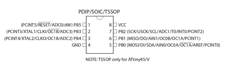
Power is supplied to VCC and GND pins.
PB on PB5-PB0 pin stand for Port B is a 6-bit bi-directional I/O port with internal pull-up resistors. Port B also serves the functions of various special features of the ATtiny45.
Reset input pin can be used as a (weak) I/O pin, but mostly is used to program the chip with th In-System Programming.
Programming Microcontroller
After reading the datasheet there are new information I gained, which I will use to program the chip.
There are may ways to program this chip, I will start with Arduino which is easy and popular.
Arduino
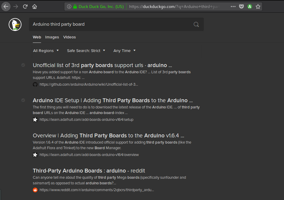
I started configuring arduino IDE to be able to program this chip. I searched for Third party boards for arduino IDE, and followed the first search result provided and looked for a way to add a board which supports ATtiny45.
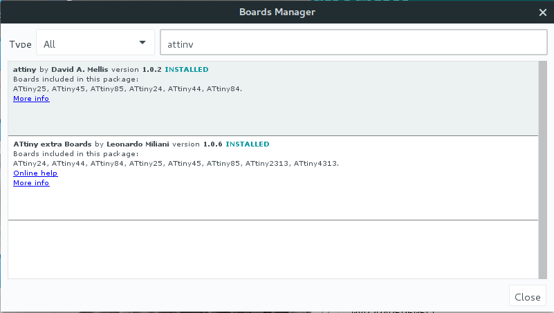
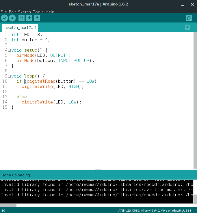
After Installing I was ready to start programming the board. In arduino I used its API to program the chip.
void setup(){
	// Defining pin functionality
	pinMode(PB3, OUTPUT);
	pinMode(PB4, INPUT_PULLUP);
}

void loop(){
	// Check if the button is pressed and turn ON the LED
	if (ditalRead(PB4) == LOW)
		digitalWrite(PB3, HIGH);
	else
		digitalWrite(PB3, LOW);
}
The intent of this program is for turning ON the LED when the push button is pressed.
AVR libc
I have also programed the chip using AVR libc only and VIM as text editor. when programming with AVR libc there is a big difference with arduino, because now you are able to manupulate registers directly. AVR libc occupies small space on the chip compared to arduino API.
#include <avr/io.h>

int main(void){
	// Defining pins and their state
	DDRB &= ~(1<<PINB4);
	PORTB |= (1<<PINB4);

	DDRB |= (1<<PINB3);

	int count = 0;

	while(1){
		// Check if the button is pressed
		if (bit_is_clear(PINB, 4){
			count++;	// increments if the button is pressed
			if (count >= 400){	// if count is greater than or equal to 400 toggle the LED
		    		PORTB ^= (1<<PINB3);
		    		count = 0;
        		}
    		}
	}
}
This program is for toggling the LED when the push button is pressed.
After writing this program I created a Makefile which is a file containing instruction used when compiling my program.
PRG = helloWorld
OBJ = helloWOrld.o
MCU_TARGET = attiny45
OPTIMIZE = -Os

CC = avr-gcc

# override is only needed by avr-lib build system
override CFLAGS = -g -Wall $(OPTIMIZE   ) -mmcu=$(MCU_TARGET) $(DEFS)
override LDFLAGS = -Wl, -Map, $(PRG).map

OBJCOPY = avr-objcopy
OBJDUMP = avr-objdump

all: $(PRG).elf lst text

$(PRG).elf: $(OBJ)
$(CC) $(CFLAGS) $LDFLAGS) -o $@ $^ $(LIBS)

# Deleting all files ending with(.o, .elf, .map, .lst, .hex, .bin, .srec) use [make clean]
clean:
rm -rf *.o $(PRG).elf *eps *.png *.pdg *.bak
rm -rf *.lst *.map $(EXTRA_CLEAN_FILES)

# For uploading hex file in the chip use [make program]
program:
	avrdude -usbtiny -[ $(MCU_TARGET) -U flash:w:$(PRG).hex

lst: $(PRG).lst

%.lst: %.elf
	$(OBJDUMP) -h -S $< > $@

# rules for building the .text ROM images

text: hex bin srec

hex: $(PRG).hex
bin: $(PRG).bin
srec: $(PRG).srec

%.hex: %.elf
	$(OBJCOPY) -j .text -j .data -O ihex $< $@

%.srec: %.elf
	$(OBJCOPY) -j .text -j .data -O srec $< $@

%.bin: %.elf
	$(OBJCOPY) -j .text -j .data -O binary $< $@

EXTRA_CLEAN_FILES = *.hex *.bin *.srec