Input device
In this assignment of designing an input device, I used one of the sensor available in our fablab.
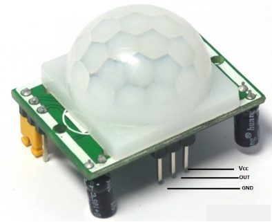
Img: Input sensor
I made a circuit which will detect a motion and Turn ON an LED.
I designed the schematic using Eagle CAD software.
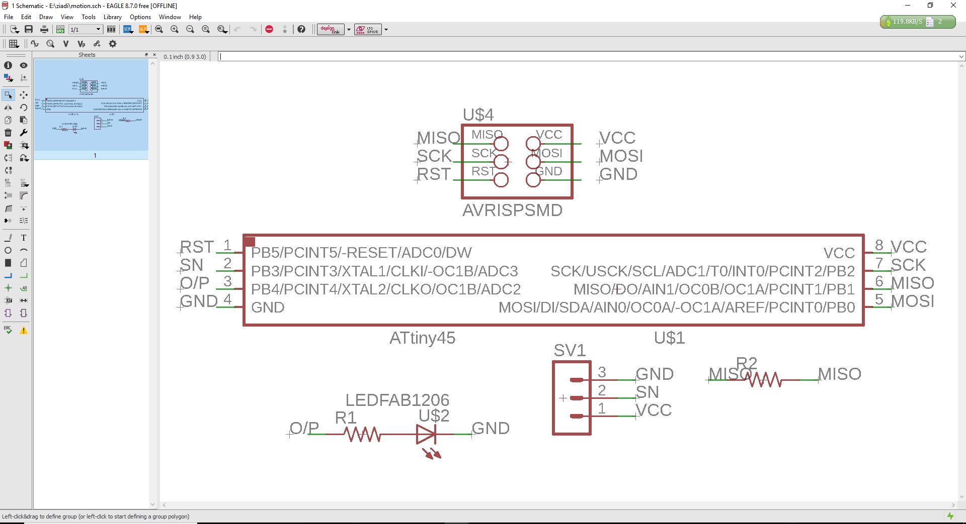
Img: Input schematic
And this is the design of the PCB board.
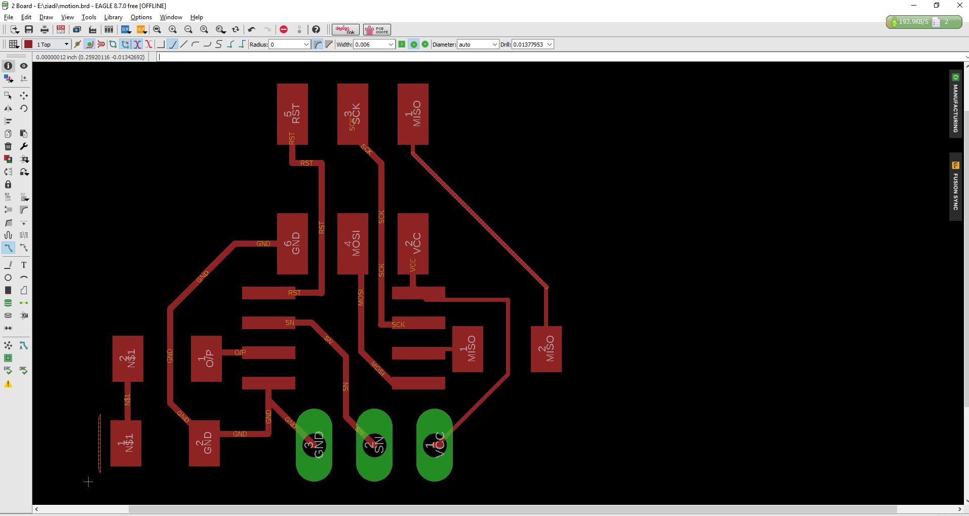
Img: input board
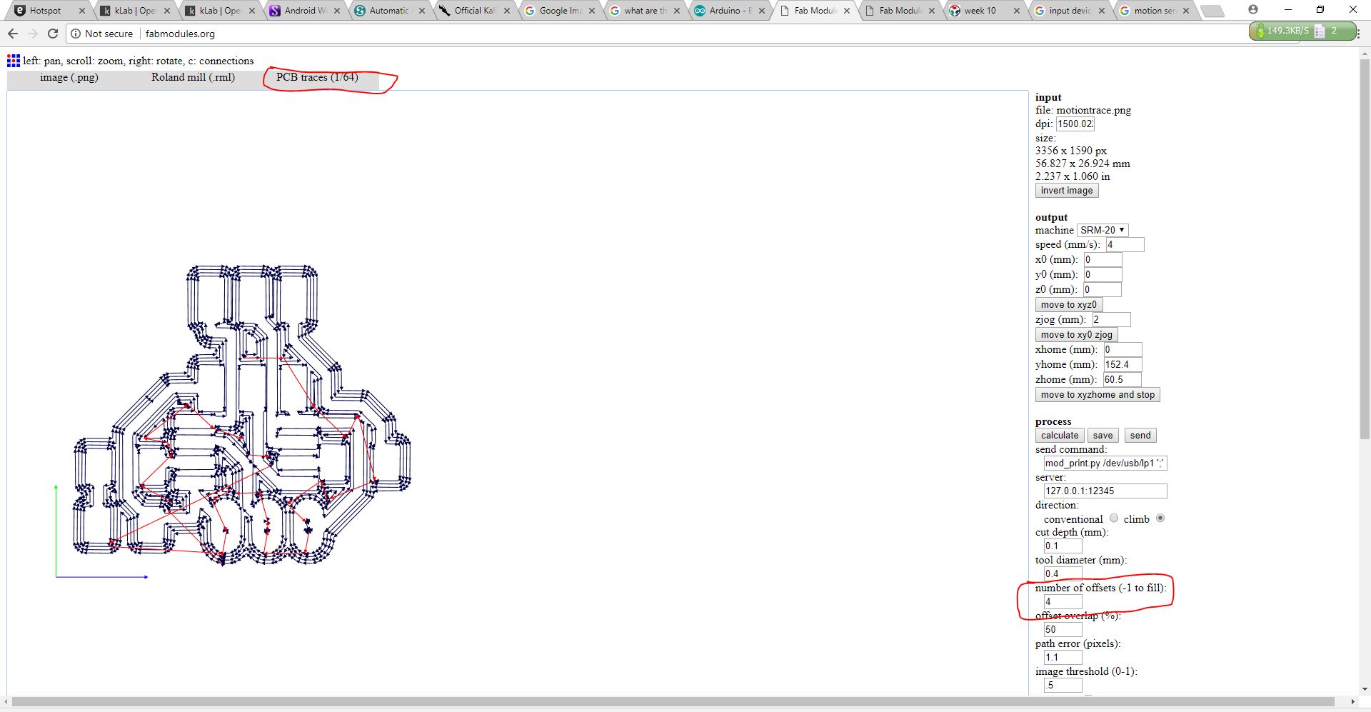
I export images of the board that I used to create a RML files.

Img: input board image

Img: input edge image
Then I continued to generate RML file to use for milling the PCB.
Img: input RML board
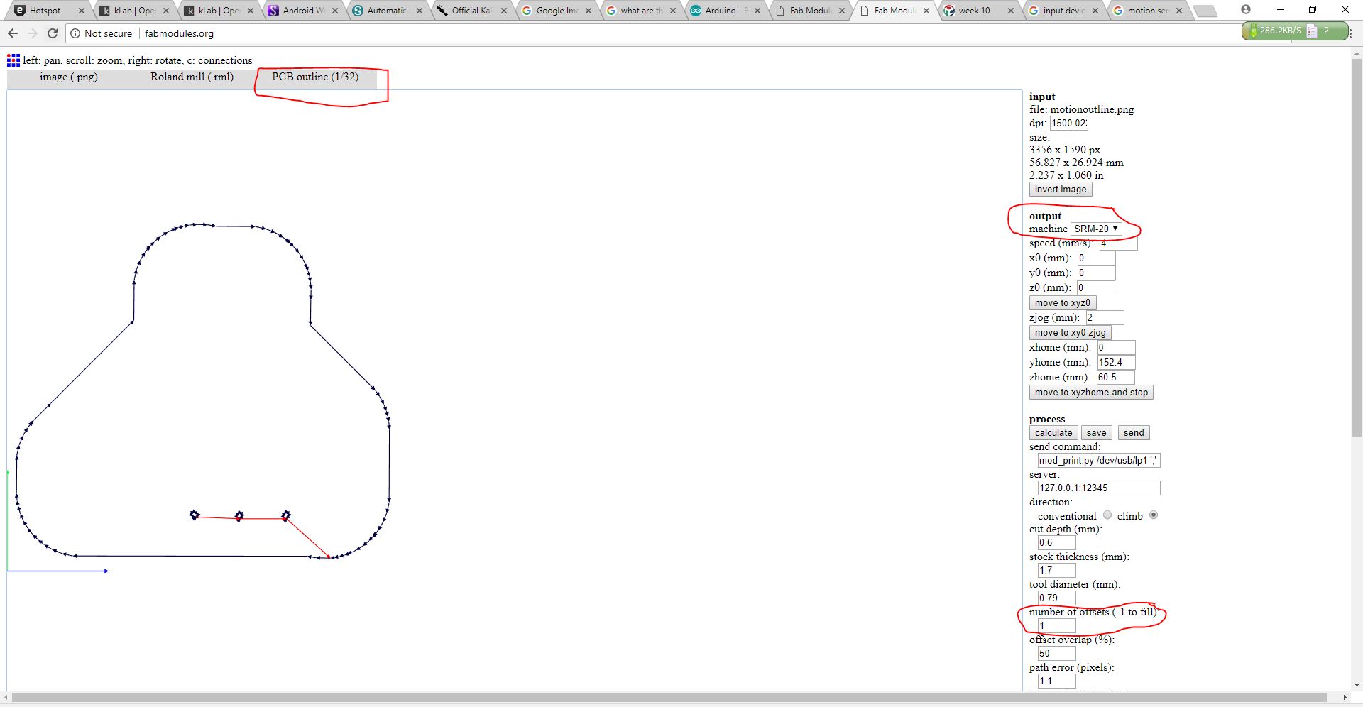
Img: input RML edge
After I started machining the board.
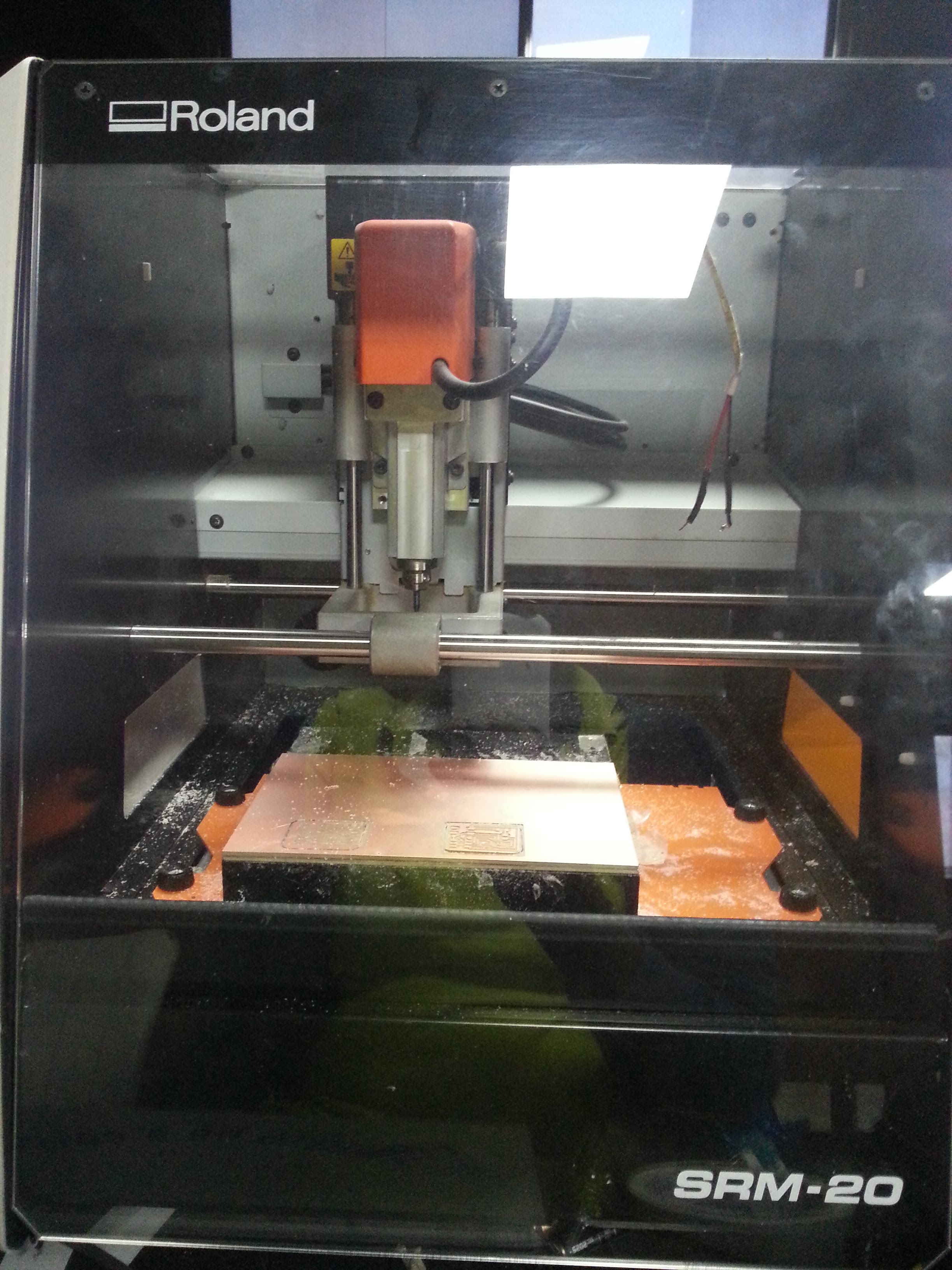
Img: input machining
I soldered the board with the motion sensor.
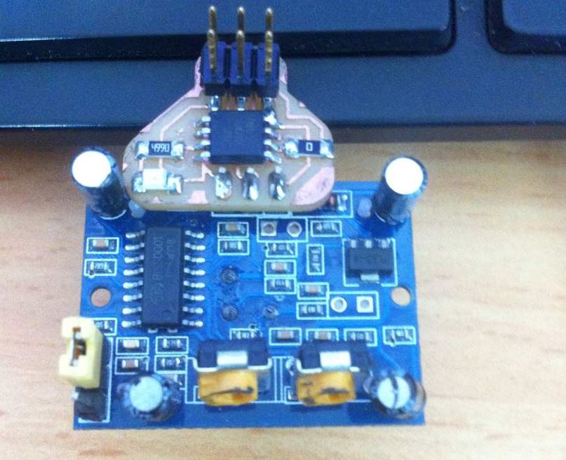
Img: input final board
I did programed it to Turn ON when a motion is detected.
int motionPin = 3;
int ledPin = 4;

void setup(){
     pinMode(motionPin, INPUT);
     pinMode(ledPin, OUTPUT);

}

void loop(){
     if (motionPin == HIGH){
          digitalWrite(ledPin, HIGH);
     }
     else {
          digitalWrite(ledPin, LOW);
     }
     delay(100);
}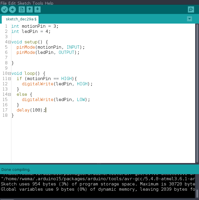
Img: input code
Files used can be downloaded Here