Output devices
In This assignment I designed LEDs Blinking and Glowing.
I started by designing the schematic in Eagle CAD software and I used an Attiny45 microcontroller.
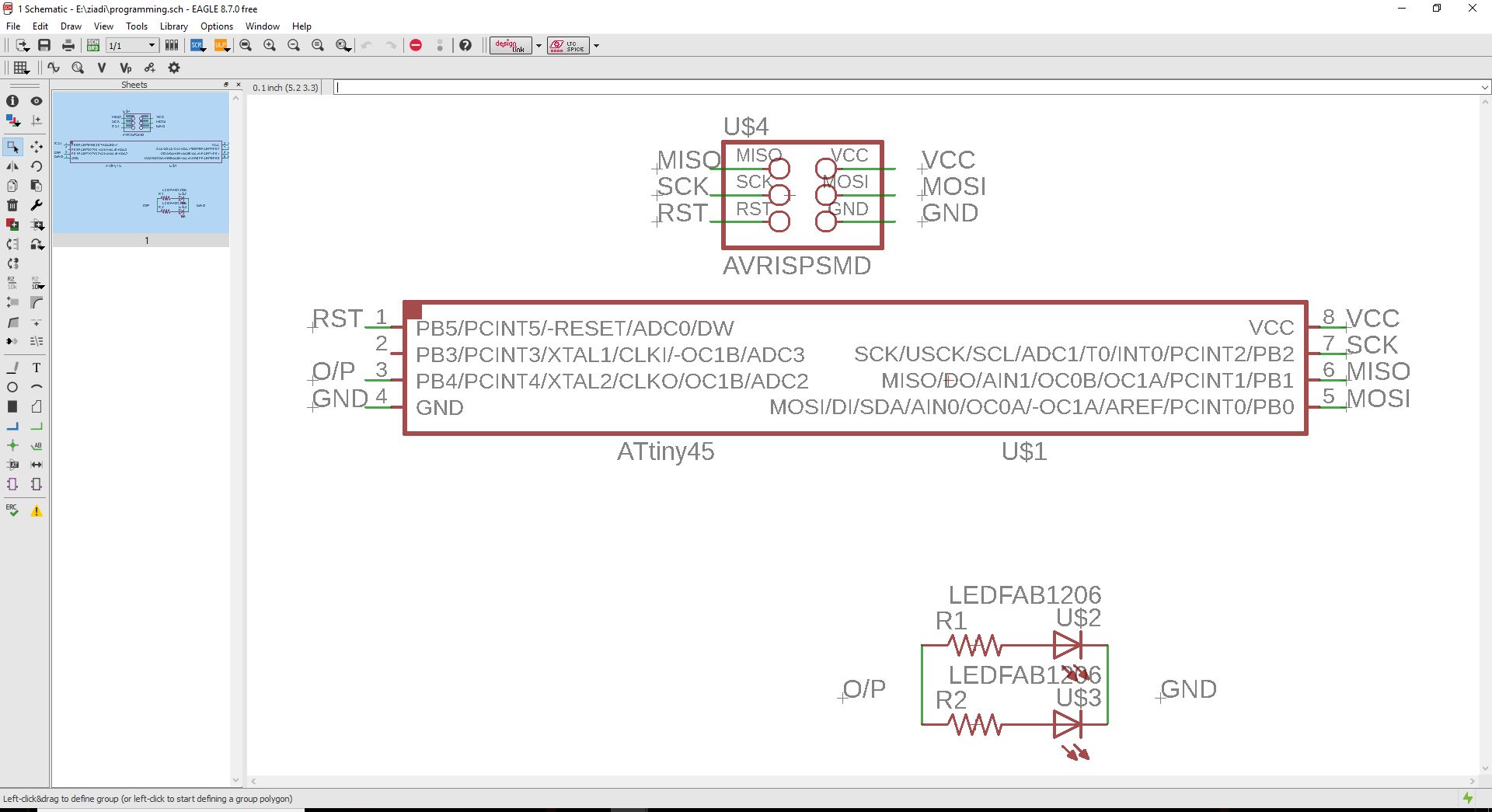
Img: output schematic
I aligned components as the way I wanted them to look on the PCB board.
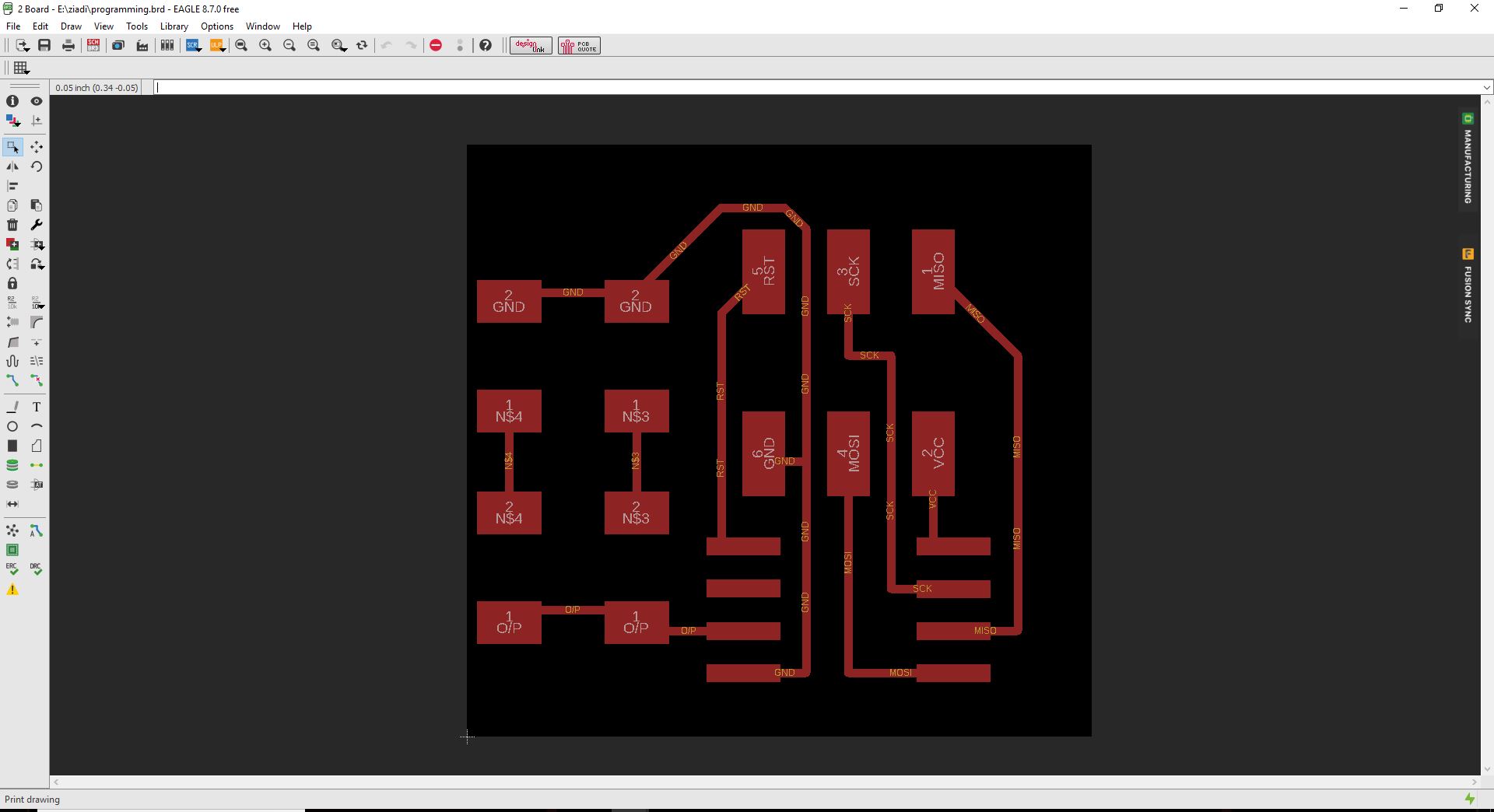
Img: output board
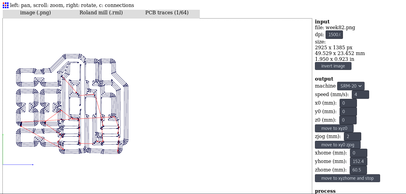
After the design I exported the PNG image to use for generating RML files.

Img: output trace image

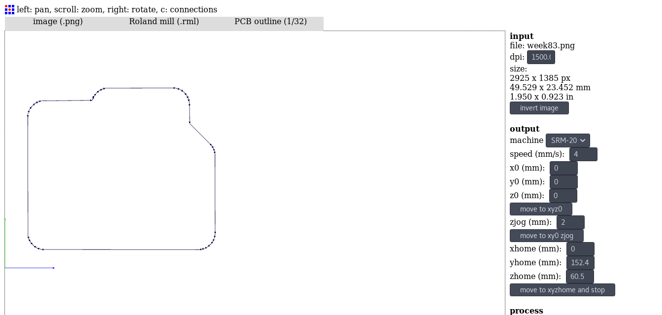
Img: output edge image
I generated the RML file using Fabmodules which I will use to mill PCB.
Img: output trace RML
Img: output edge RML
After milling the PCB I soldered all components on it and tested it with multimeter to check if all connection are good.
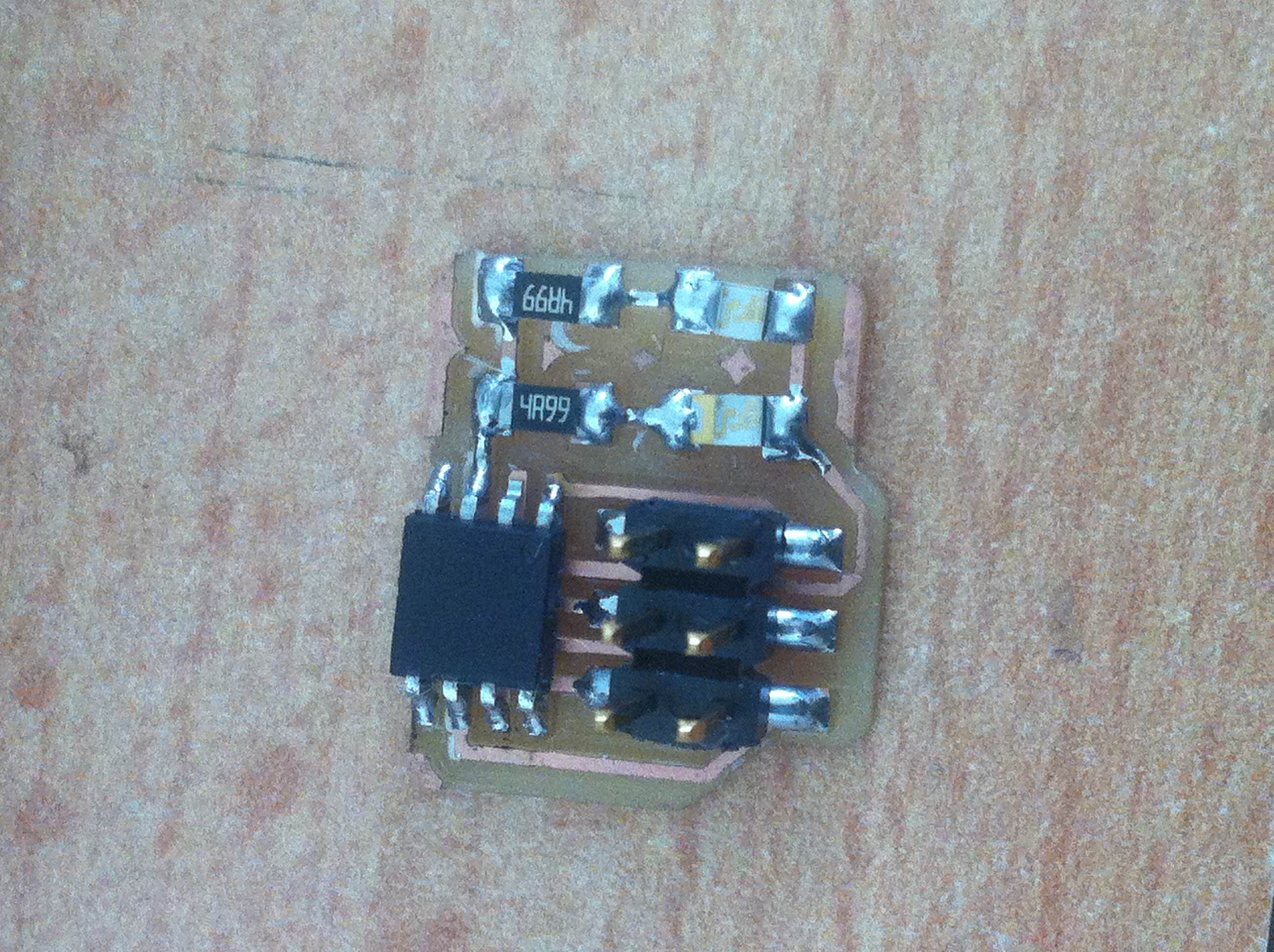
Img: output soldered board
I continued to programme the board. I wanted to make the board to blink for sometime after and start glowing.
int ledPin = 4;

void setup(){
     pinMode(ledPin, OUTPUT);

}

void loop(){
     digitalWrite(ledPin, HIGH);
     delay(500);
     digitalWrite(ledPin, LOW);
     delay(500);
     digitalWrite(ledPin, HIGH);
     delay(500);
     digitalWrite(ledPin, LOW);
     delay(500);
     int i;
     for (i=0; i<250; i+=50){
          analogWrite(ledPin, i);
          delay(500);
     }
     for (i=250; i>0; i-=50){
          analogWrite(ledPin, i);
          delay(500);
     }
}
Here's an image of the program I wrote.
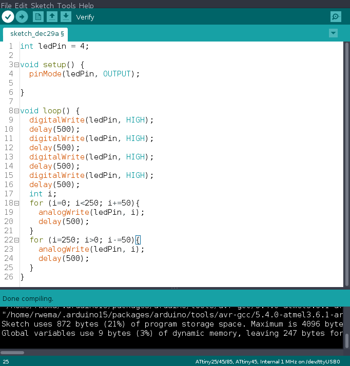
Img: output program
Files used can be downloaded Here