Electronic Design
In electronic there many software to use for designing PCBs. I did prefare to use the one most of my colleagues were using which is CAD soft Eagle to make PCBs.
I started by learning basics of the software before I designing, I thank my colleagues to help during the process of the assignement.
I first designed a schematic of the circuit by placing component I want to use.
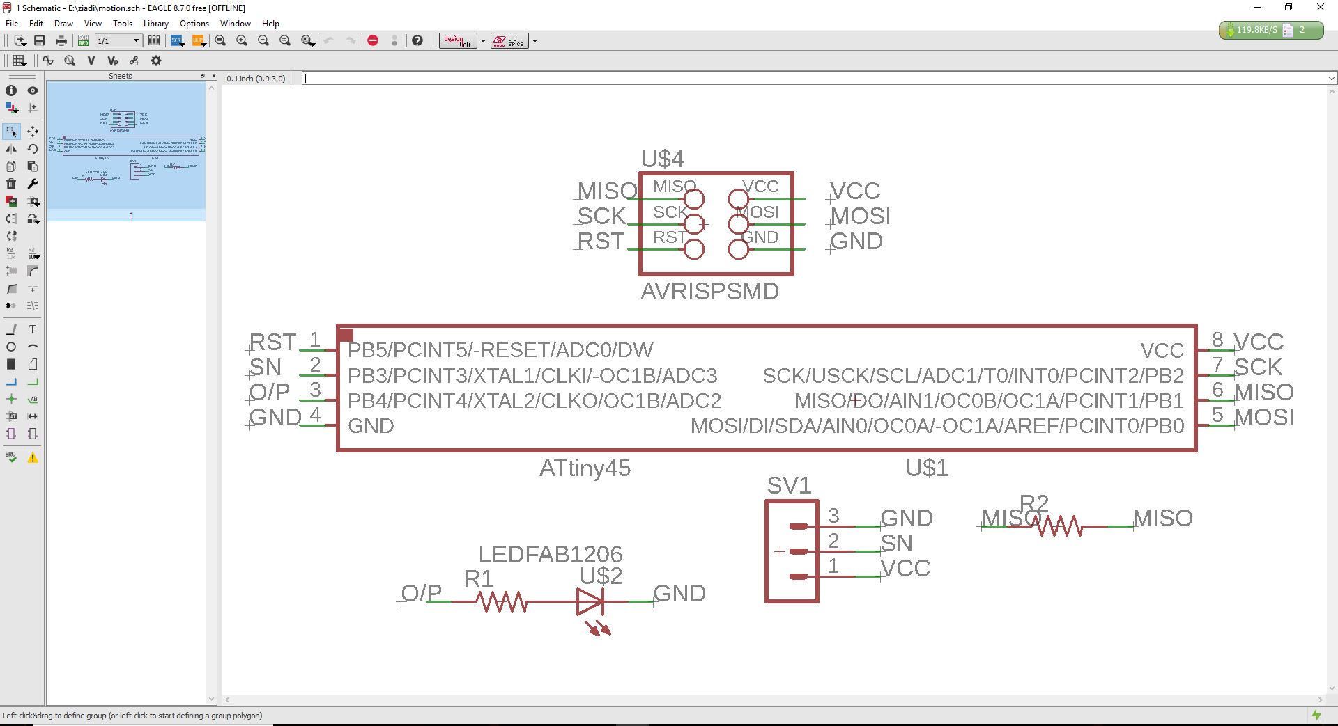
Img: schematic design
After designing the schematic, I continued to design the PCB.
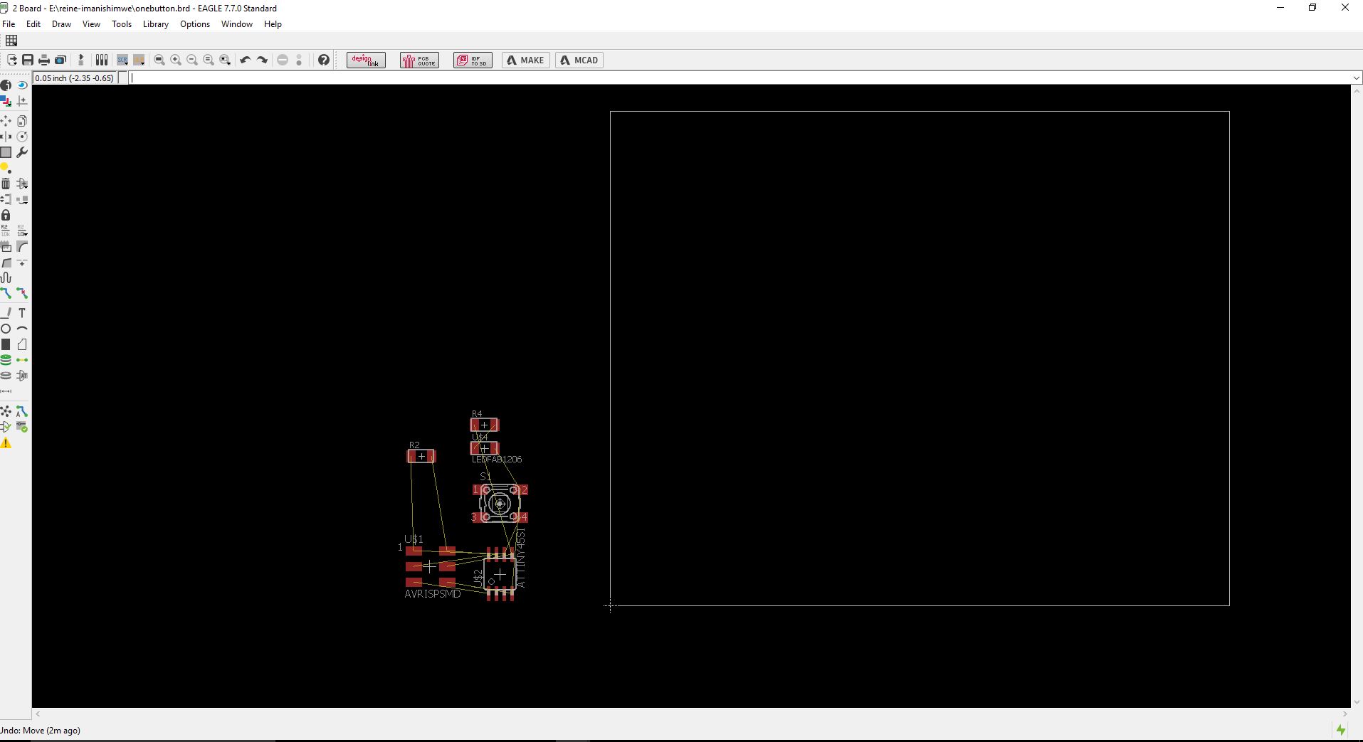
Img: board design
This part was the most difficult to be able to place componets the right way.
Img: component place
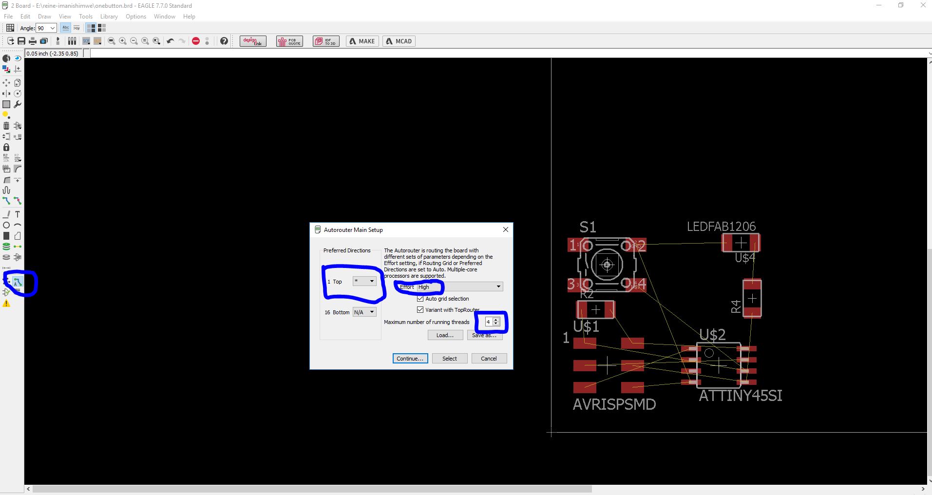
After place all components I used autoroute since cause I found it easier.
Img: autoroute
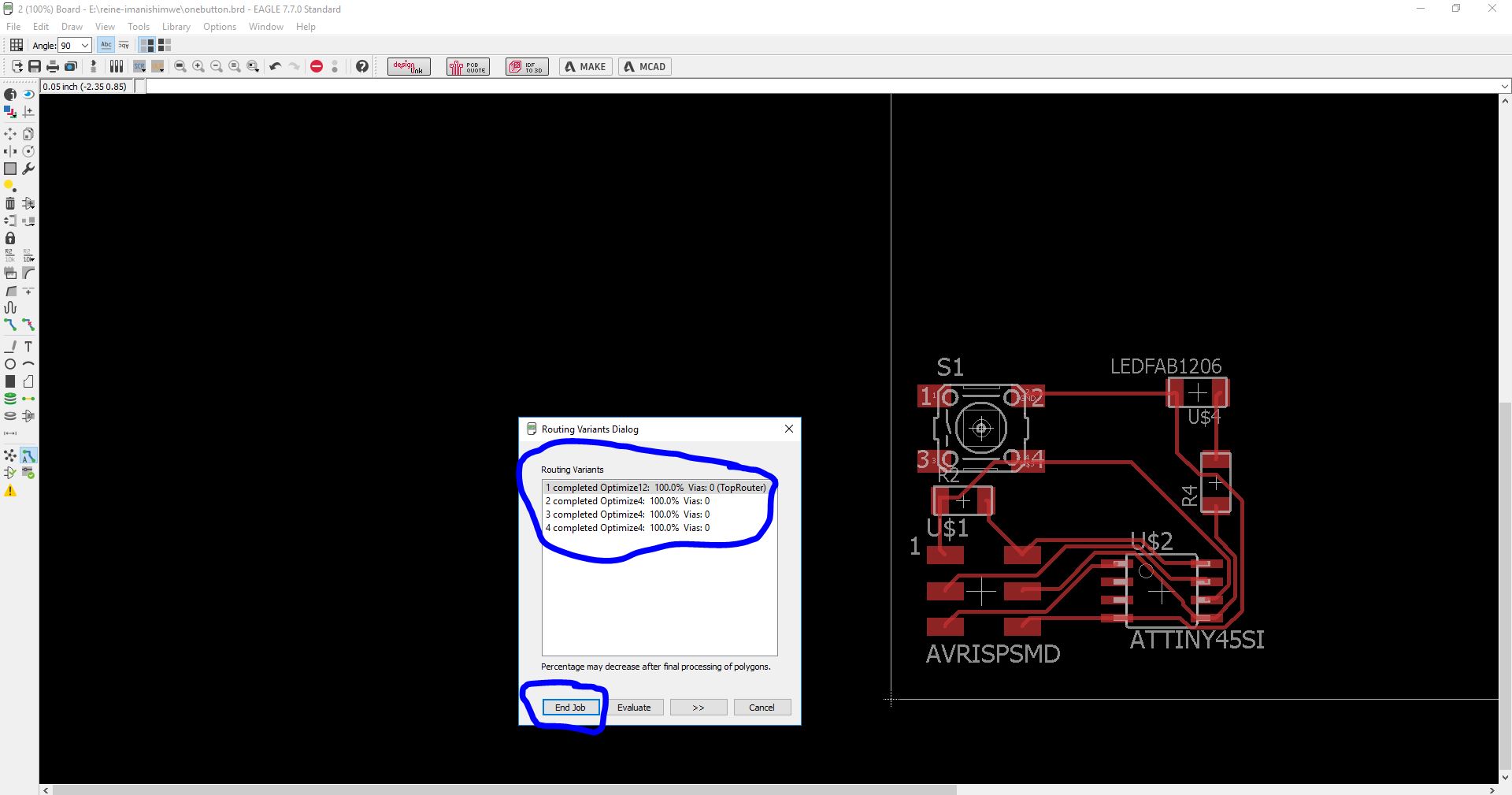
This is the final look of the PCB design.
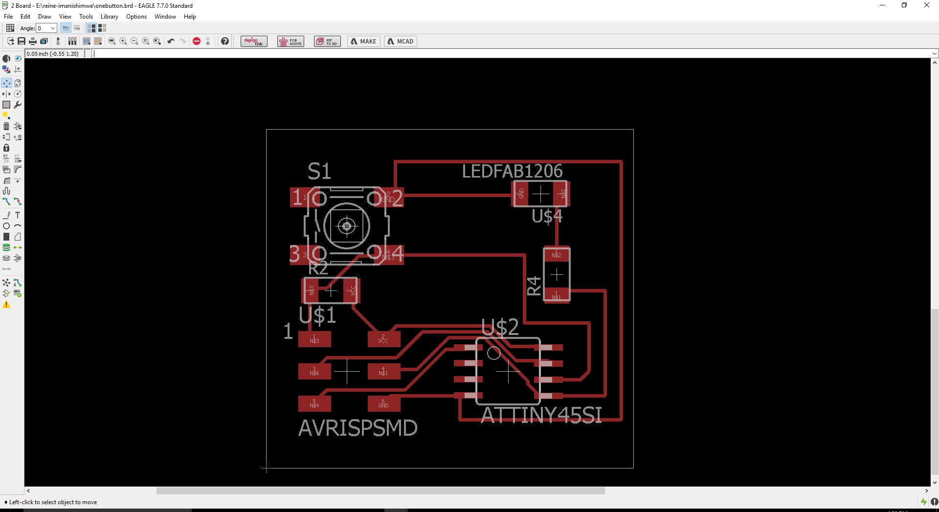
Img: PCB design
I exported an image of the PCB board and converted it in RML file for using in roland monofab.
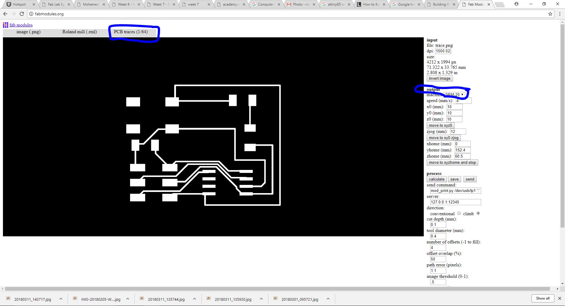
Img: exported image
At this point I had my design ready to be milled.
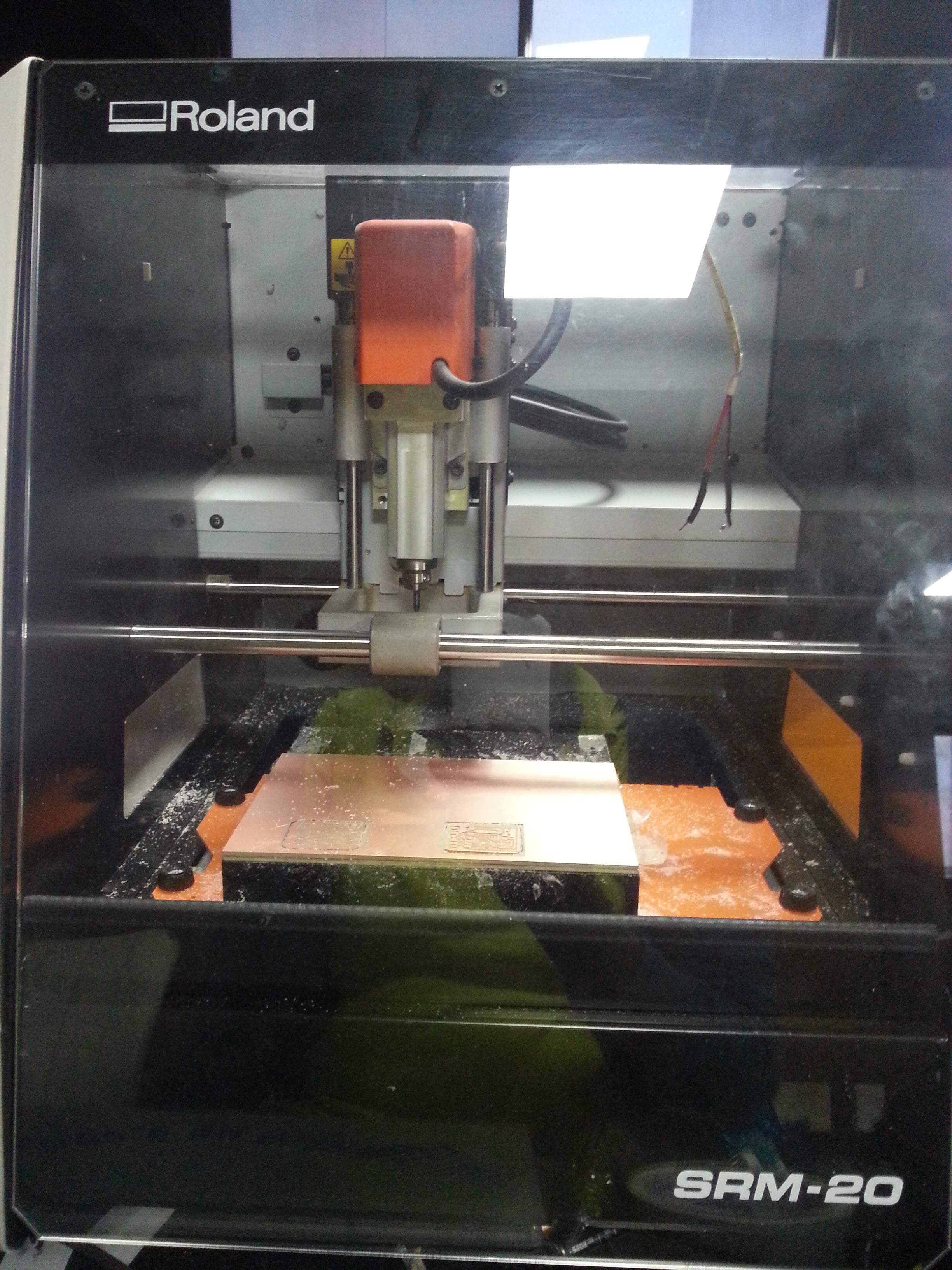
Img: Milling PCB
After milling I assembed my component so I can start soldering them.
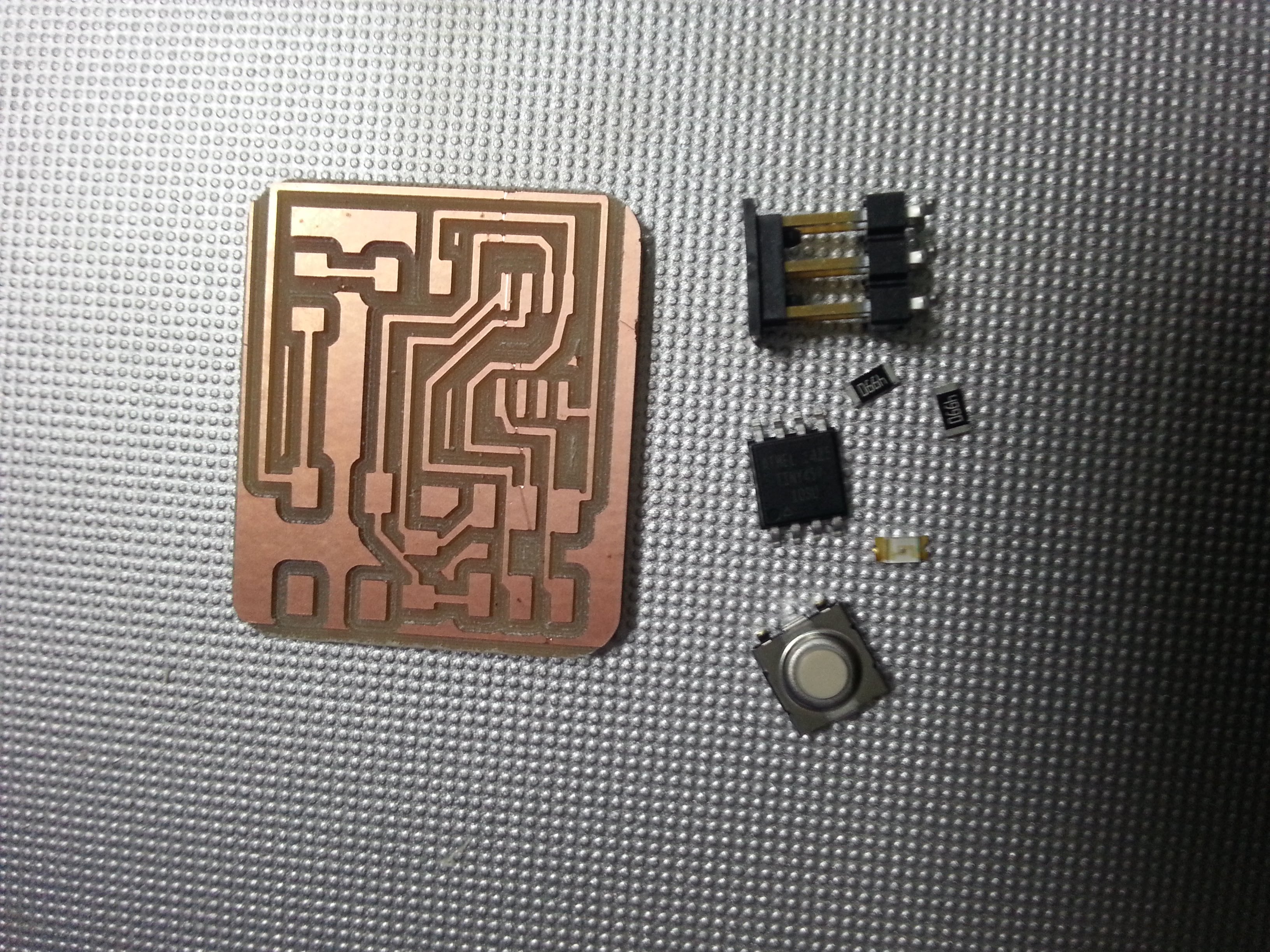
Img: components
I started to solder each component in its place.
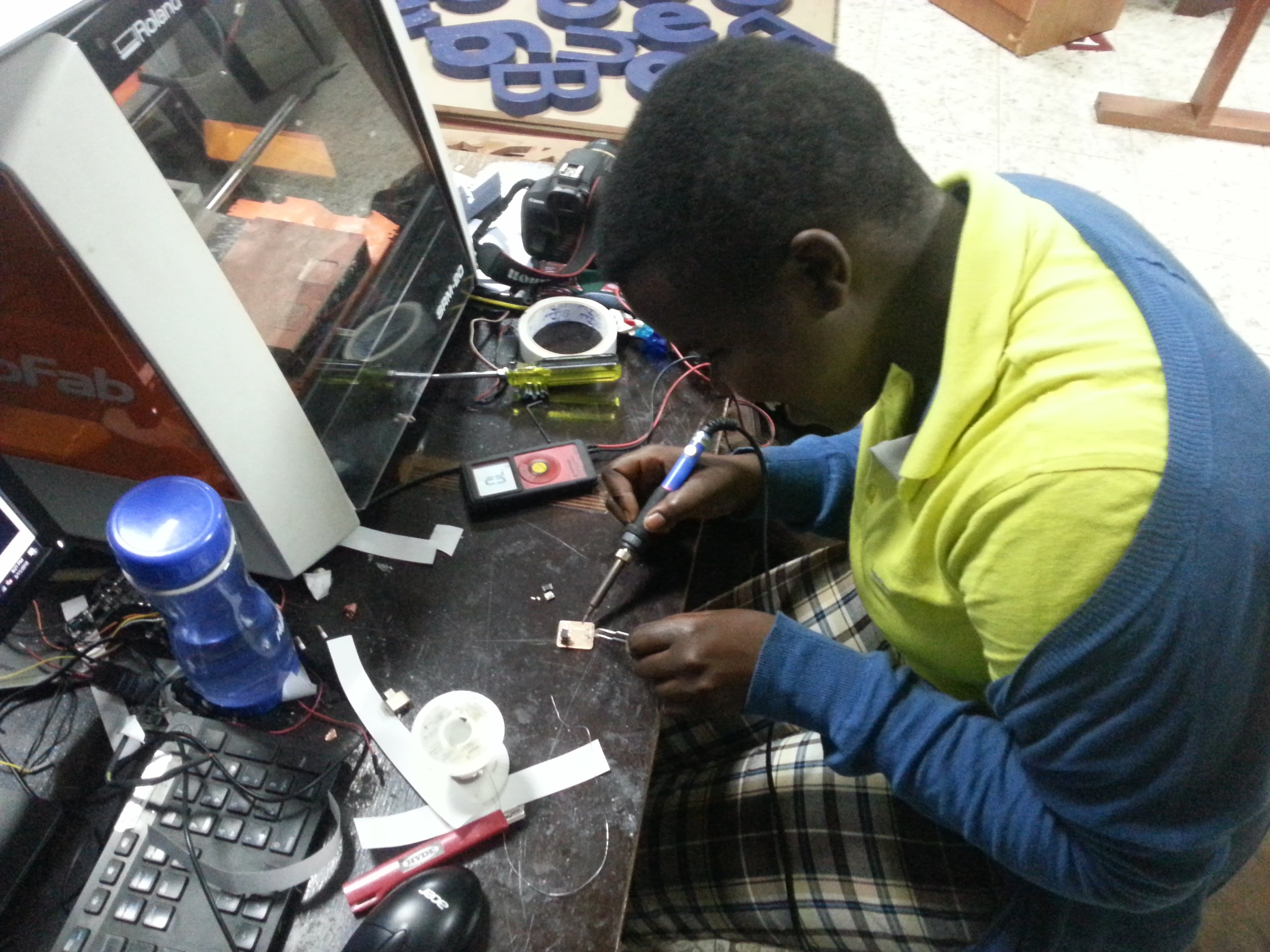
Img: soldering 1
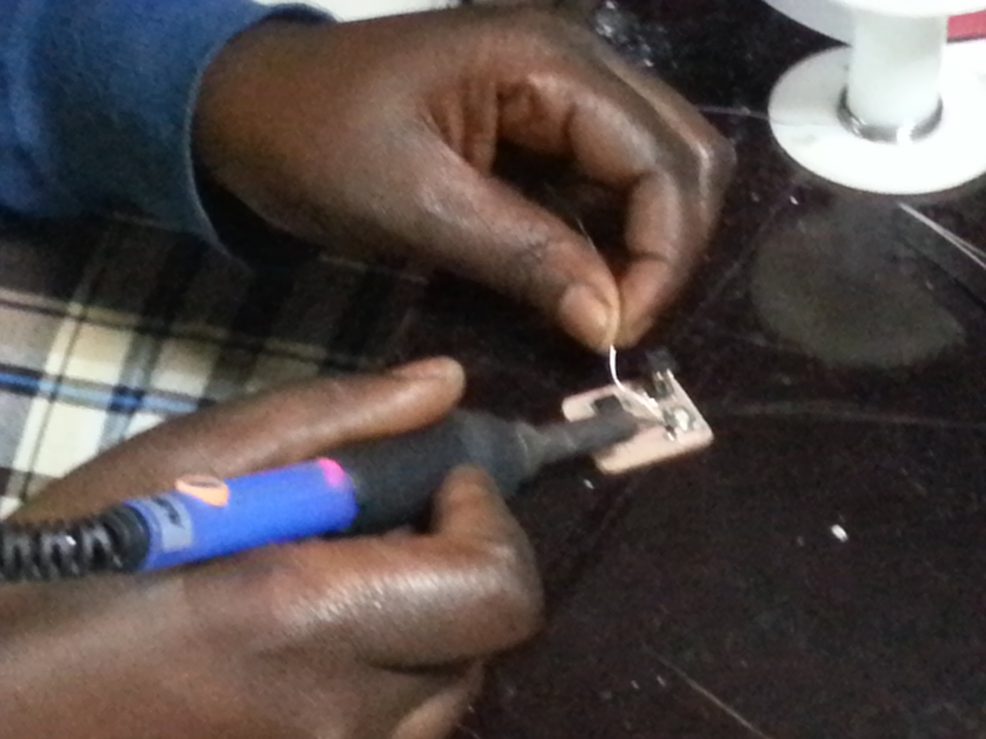
Img: soldering 2
This is how the board looks after soldering it.
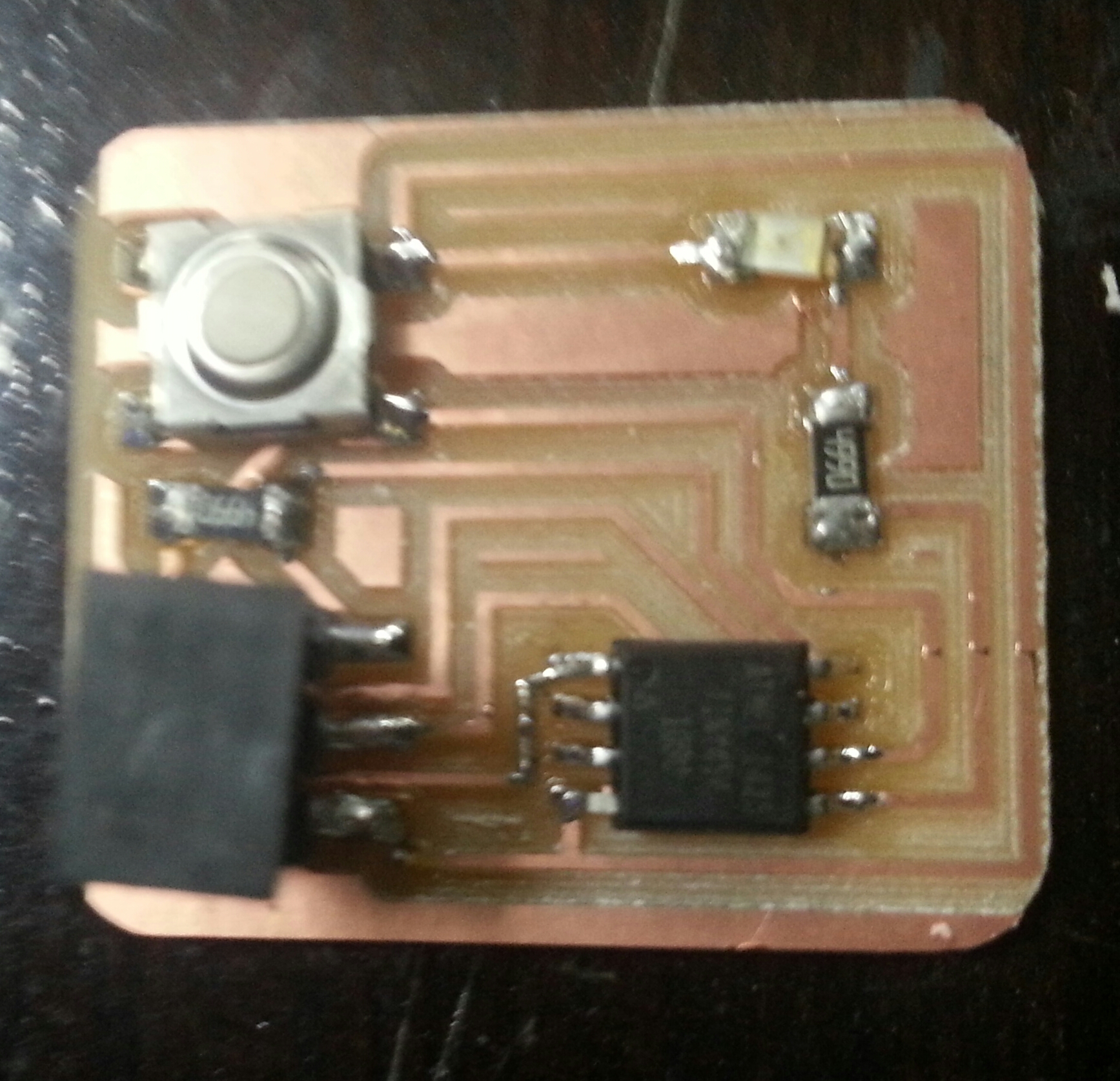
Img: soldered board
I also programmed the board after soldering it.
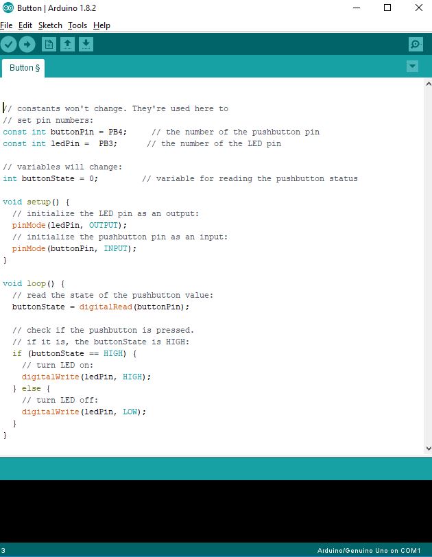
Img: Program PCB
Files used can be downloaded Here