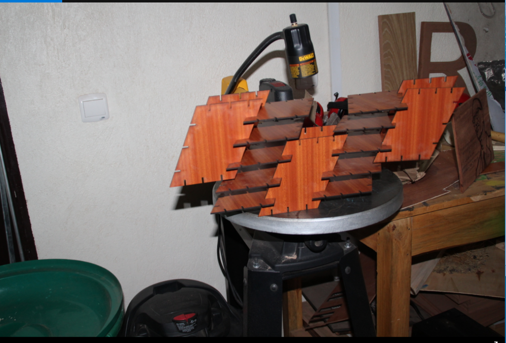
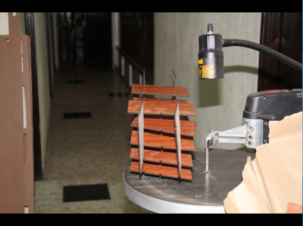
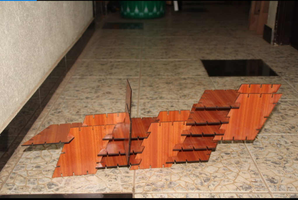
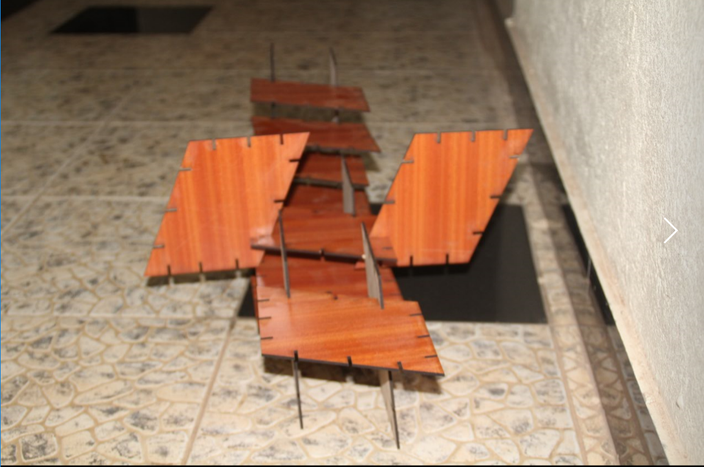
Design and make a corrugated cardboard press-fit construction kit.
The week started with understanding how a drawing software interfaces to a cutting machine. From either the vectors or the rasters created with the CAD tool, a text file is generated where the movements of the machine are coded. Formats differ quite a lot, and some need a proprietary software to be generated. In sequence, this page reports the work I did with the vinyl cutter and the laser cutter. Included the design files and photos of the finished projects.
First I had to understand What Parametric designs are and I found out it is a process based on algorithmic thinking that enables the expression of parameters and rules that, together, define, encode and clarify the relationship between design intent and design response
In Brief:It is a way to make all dimensions in the design related having algorithmic ratios so that when you change one dimension others will also change accordingly.
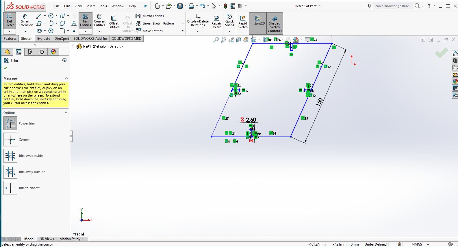
Designing the parametric parts into Solidworks
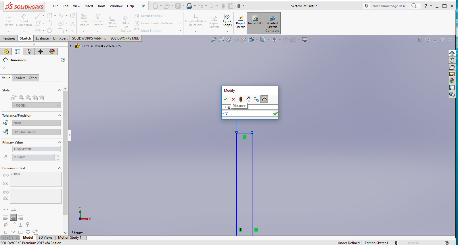
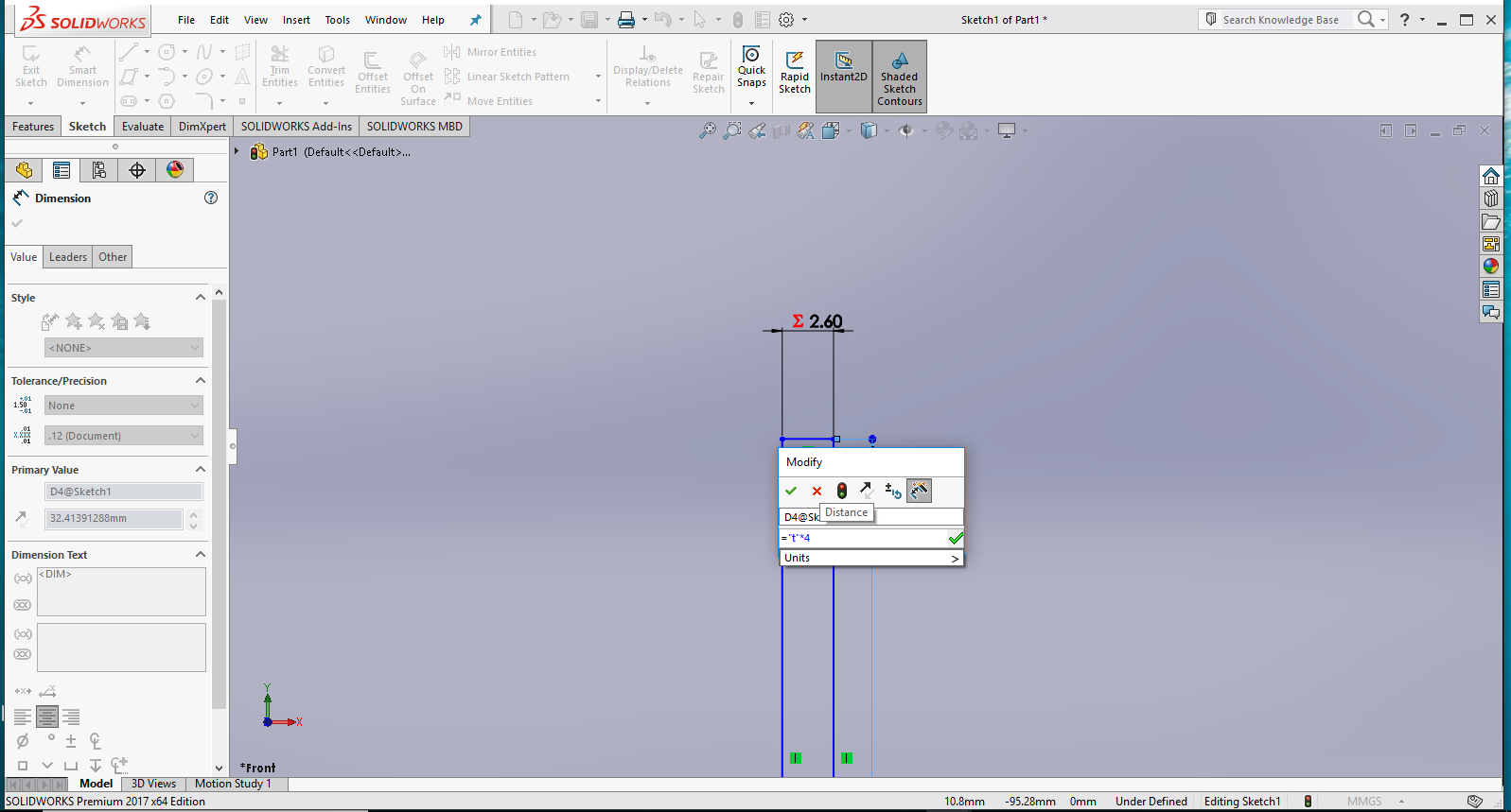
>
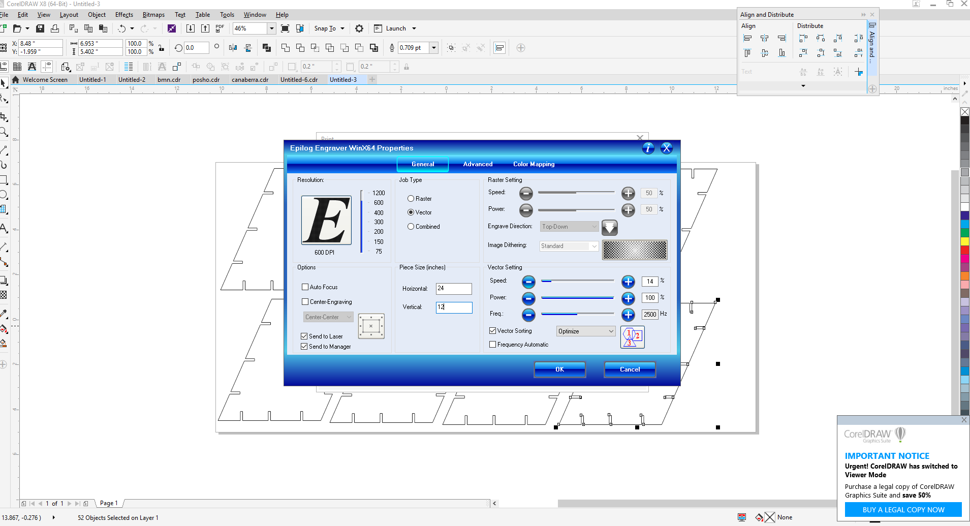
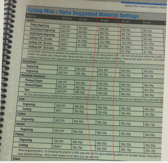
Setting the Power to use on a laser cutter
After importing the solidworks designs saved in .DXF in Coral draw.I wanted to print using Epilog Mini laser cutter. In particular with you have to be carefull since more power can burn it and also less power could result in not cutting,so you have to be careful with power and speed.
In this case i decided to use a speed of 14% and a power of 100%
.png)
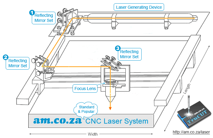
Laser Cutter details
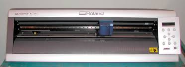
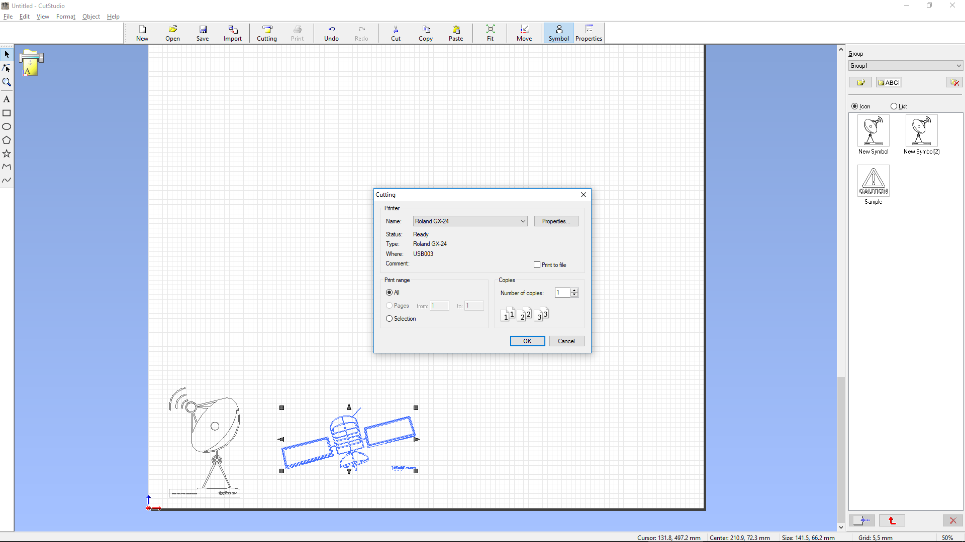
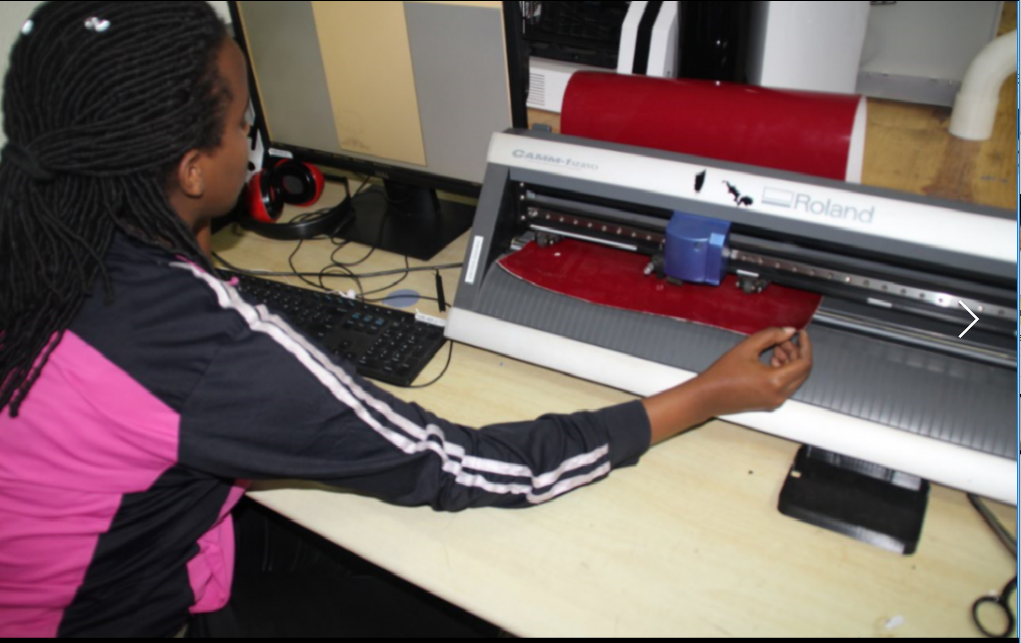
VINLY CUTTER
With Vinly cutter I imported 2 images one of a full satellite and one of an antenna that symbolises a groundstation which i downloaded on google,Then I imported them into CutStudio and cut it.After I rubbed it on my computer for it to stick well.
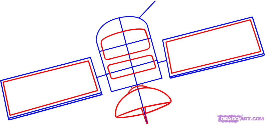

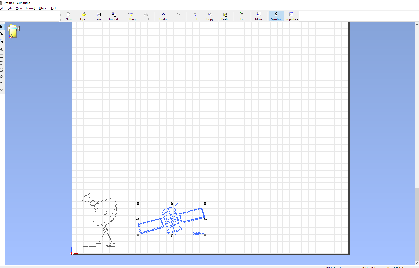
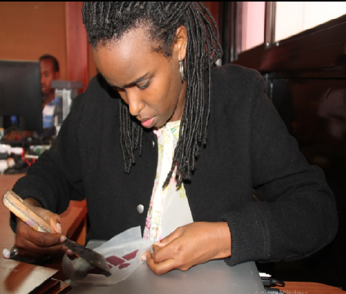
So about taping I added a masking sheet on the sticker and rubbed it gently so that the cut parts may stick to it and be also be gently rubbed to the back of my computer at their turn.
I had no problem rubbing it so I think taping on a masking sheet is a good way to apply your stickers.

Some details about Vinyl cutter
Its Mechanical Resolution is 0.0005”,its Cutting speeds up to 20 inches per second and also its power Max down force of 250 grams
Challenges I met
The challenge I met was I sometimes failed to adjust the nozzle and it would sometimes cut from a lower depth and damage the sticker or it would not cut because I didn,t well adjust te nozzle.
The other problem was the resolution of the images I was importing when it was lower than 96dpi it couldn't be imported.