Electronic Design
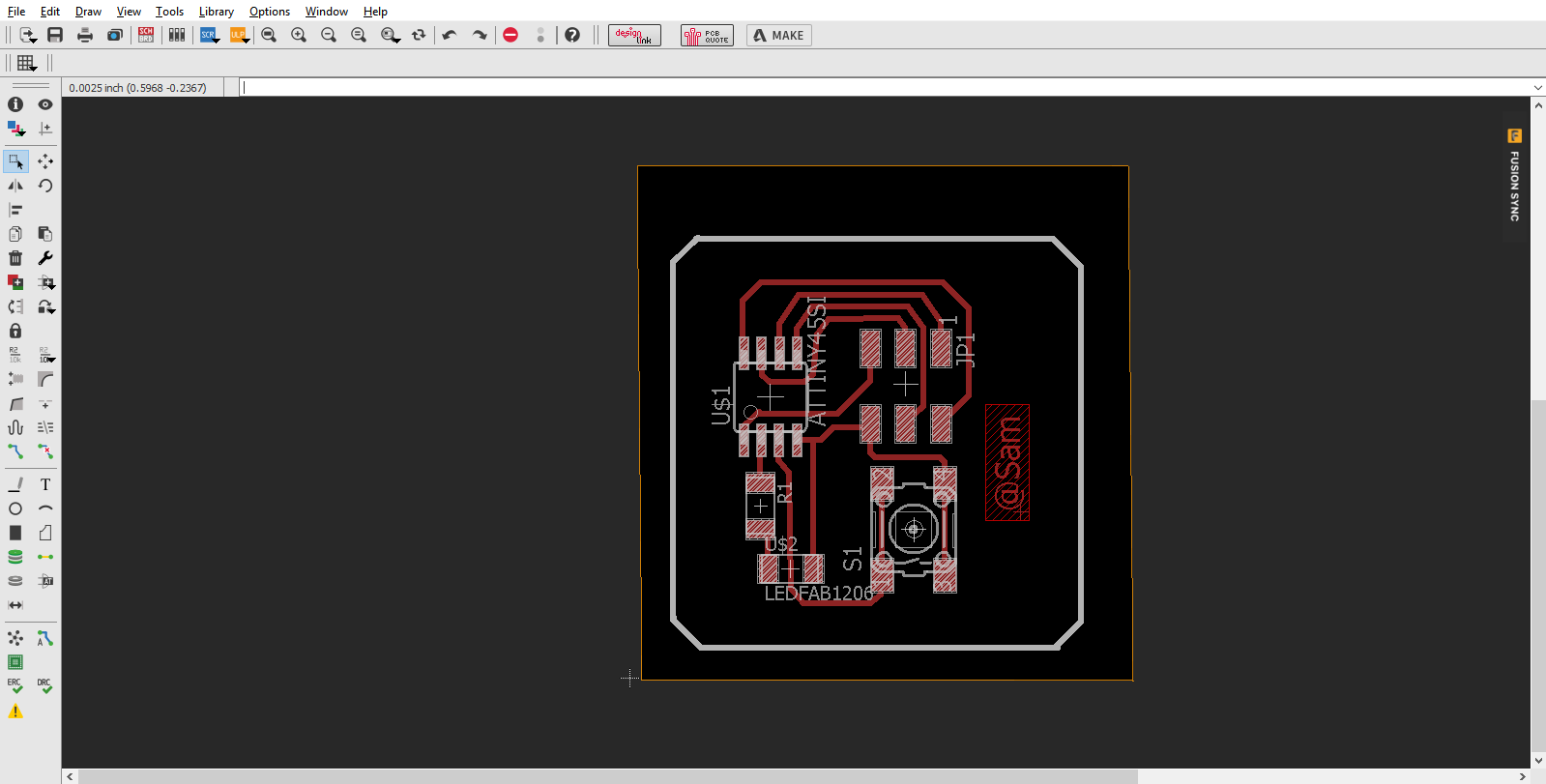
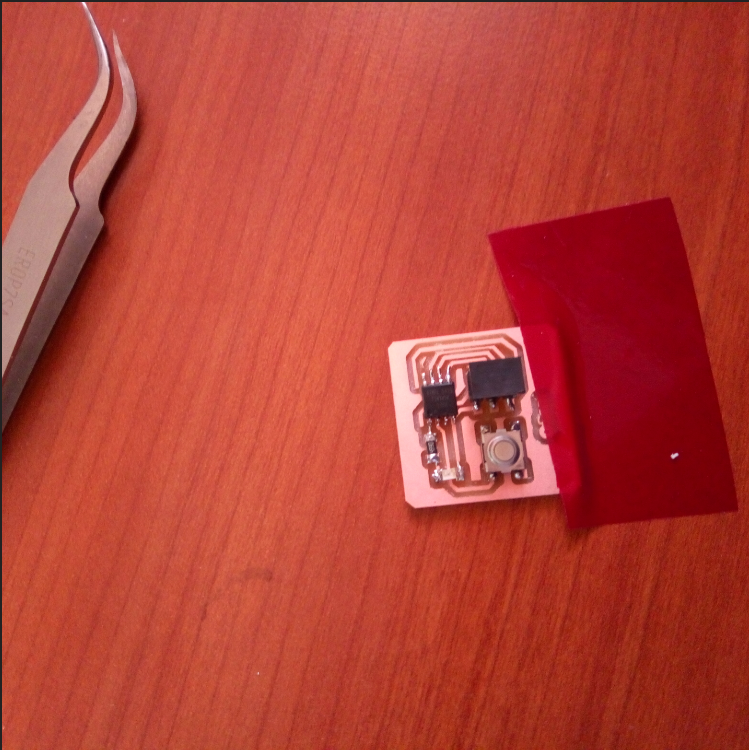
Although I am not new to some of the electronics components and soldering,I am very new to its design!So I first downloaded EAGLE software as it is the handiest Electronics Software design I was advised to use,and then followed some tutorials on YouTube and went for A HelloWorld Circuit that had MANY various components with very easy when doing schematics although the main Fab Library wasn't present in the software's library so I had to import it.Then I had To make the traces in the board this was a pretty hard as I am not anyhow used to it and there were a lot of components to be connected that I also had to use Jumpers in the circuit,so I also saw how to ground it then I grounded mine and when I went to print it It couldn't be printed.I tried many times but couldn't print the Roland Mill couldn't trace it immediately moved back the Bed.So I made another one with less components and printed it.
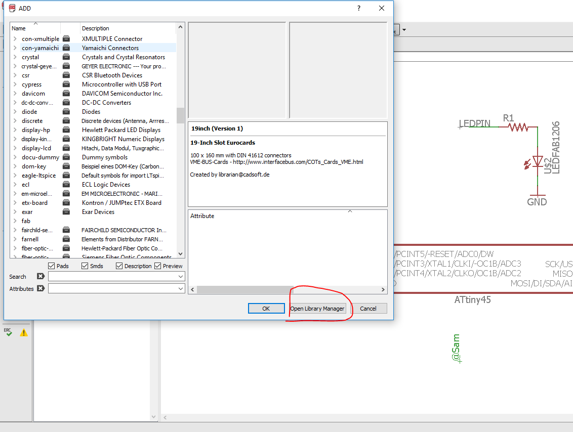
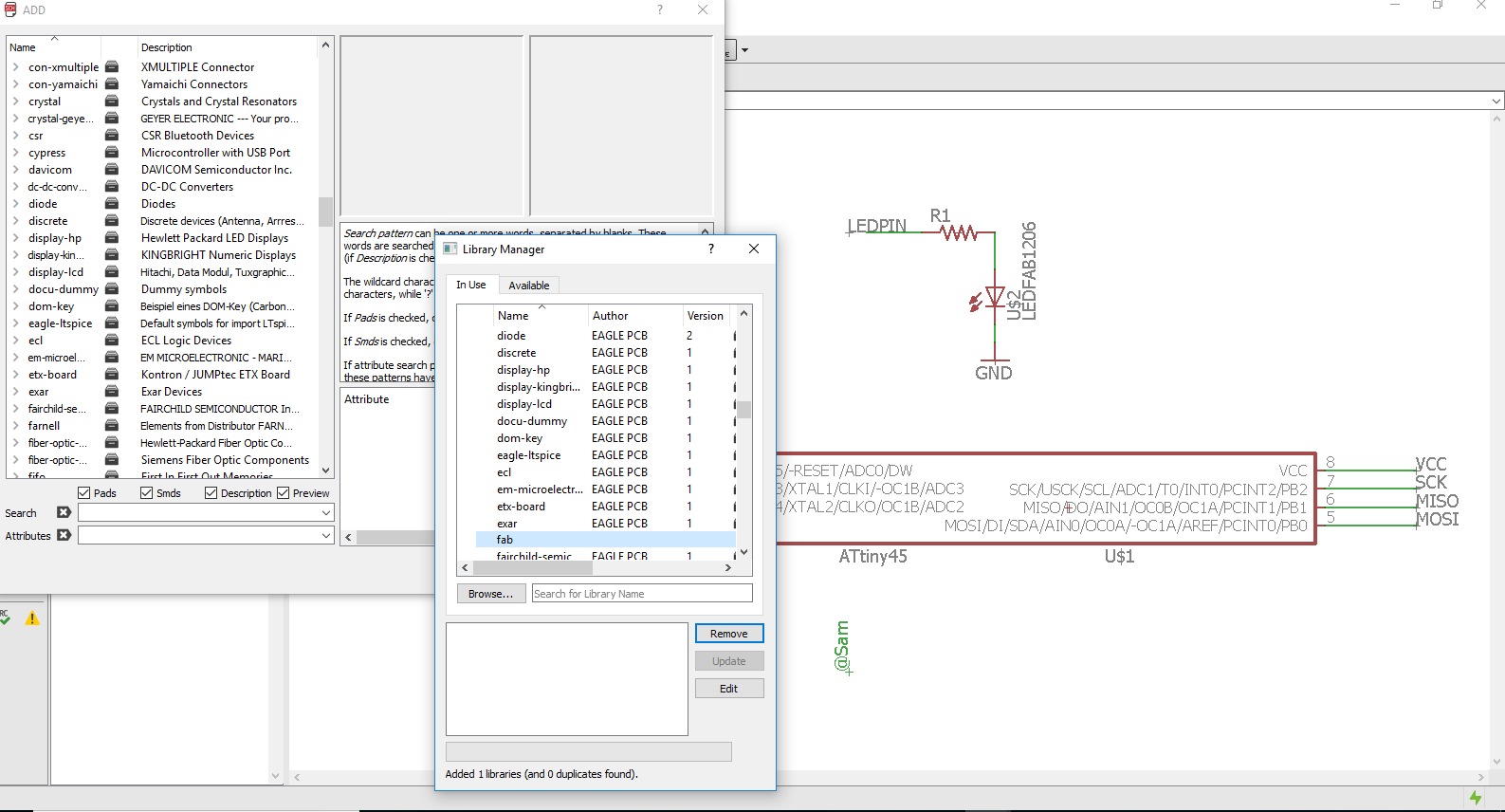
So step by step I used EAGLE software that a FabLab attendee gave me (Please find the set up attached in ALL files used) then I installed and started using it.The 1st step is to identify the names of the components that you want to use and find them in the libraries present in the software.
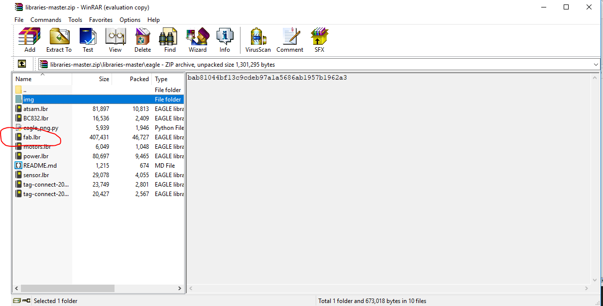
 But most of the times I wanted to use the components present in our Fabstore so I had to look for The FabLibraryin order to match the components that are present,so i downloaded it as a zipped document,unzipped it,found the library and added the library in eagle.
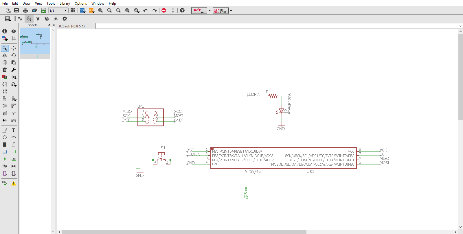
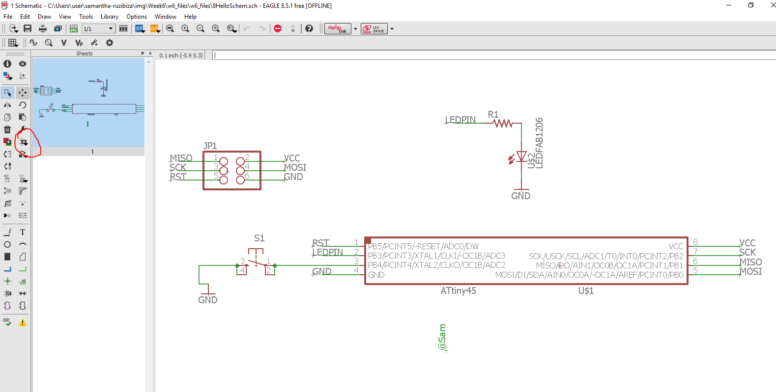
For more tutorials please find them onYOUTUBE So for the electronic design we are supposed to make a Helloworld board that contains a push button,and optionally a LED
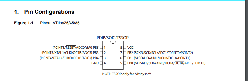
When designing the most important the microcontroller is the most important as it contains the microprocessor that performs the instructions and tasks sent when embedded from the computer.So I have to find its datasheet in order to connect all the components on the right pin On the datasheet are all infos that indicate the right pins
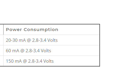
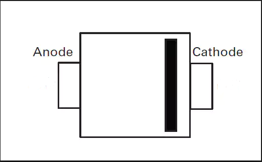
And as per the board needed only 1 LED as an ouput device and a push button as an Input device both acting as digital inputs(devices that only accept digital signals) then I connected them to digital outpots indicated in the datasheet. After that I had to learn how to connect the LED one port is connected the microcontroller for it to receive the instructions as well as the power(That's its positive part),the power that comes in is 5V and the average LED power consumption is 2.3-3.4Volts so I needed to add a resistor having resistance to the passage of the 5mA electric current. And for that I used the following formula

from there I put a 500ohm resistor
And as per the button it had to be connected only to the microcontroller receiving signal and power from there and negative connections to the GND
One important feature is that GND always corresponds on the negative polarity of the component.