Assignment 11_input devices
01 measure something: add a sensor to a microcontroller board that you have designed and read it (individual)
For input, I decide to explore the ultrasonic sensor because could be very useful for my final project so the kids could interact with the modules.
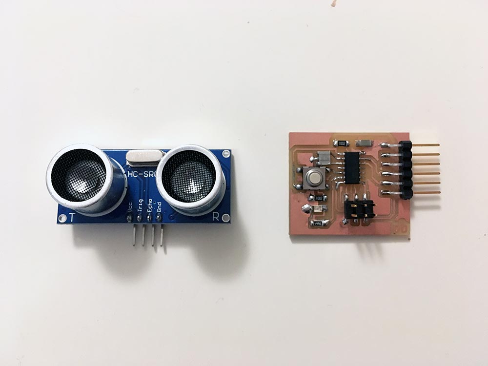
An ultrasonic sensor is a device that measures distance by sending out a sound wave at a specific frequency and listening for that sound wave to bounce back. The sensor includes an ultrasonic transmitter, a receiver and a control circuit. By recording the elapsed time between the sound wave being generated and the sound wave bouncing back, it is possible to calculate the distance between the sonar sensor and the object. (Definition from Nairobi.)
The sensor has four pins only. VCC (Power), Trig (Trigger/transsmision/OUTPUT), Echo (Receive/reception/INPUT), and GND (Ground).
I follow the instructions from Geek Factory, I decided first to try it with an Arduino board, and then use the board I design to the electronic design week . You can program the sensor downloading a library or not, for this first time I decide to use the library to understand how to download it.
First, I download the NewPing library that I need to this sensor following the tutorial of Geek Factory. The steps to follow were:
- Download the library we need (usually a ZIP file)
- Open the IDE of Arduino and follow Sketch > Import Library… > Add Library
- Choose the ZIP file
- If we go to Sketch > Import Library, we should see the library
(PROTOTYPE WITH ARDUINO PCB)
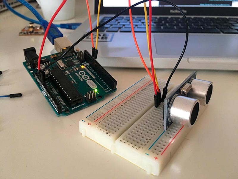
Then, I connect the Arduino board and my sensor like the image of the website:
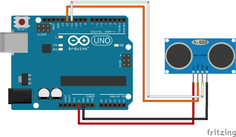
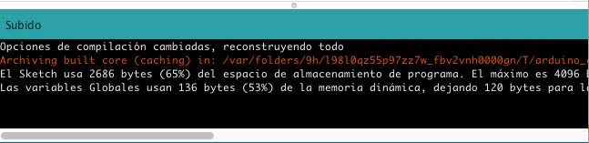
I copy and copilate the code of the web to program my sensor with the Arduino board, all the sketch use 11 % of the storage.(imagen)
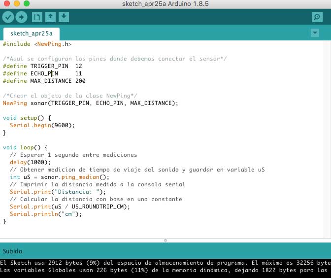
#include NewPing.h

/*Config of pins*/
#define TRIGGER_PIN  12
#define ECHO_PIN     11
#define MAX_DISTANCE 200

/*Create NewPing*/
NewPing sonar(TRIGGER_PIN, ECHO_PIN, MAX_DISTANCE);

void setup() {
  Serial.begin(9600);
}

void loop() {
  // Wait 1 second between measurements
  delay(1000);
  // Obtener medicion de tiempo de viaje del sonido y guardar en variable uS
  int uS = sonar.ping_median();
  // Print the distance in Serial Monitor
  Serial.print("Distancia: ");
  // Calulate distance
  Serial.print(uS / US_ROUNDTRIP_CM);
  Serial.println("cm");
}
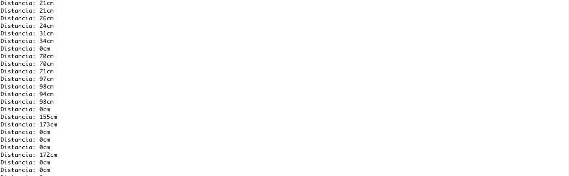
The sensor works very good; first I measure different distance with my hand and then I measure how far away could measure the sensor, the maximum the first measure it was 173 cm (I had the maximum set on 200 cm), the maximum ratio of the sensor is 250 cms.
MY PCB
For this assignment I use the board I design for Electronic Design Week, you can check the process of design and fabrication in that week.
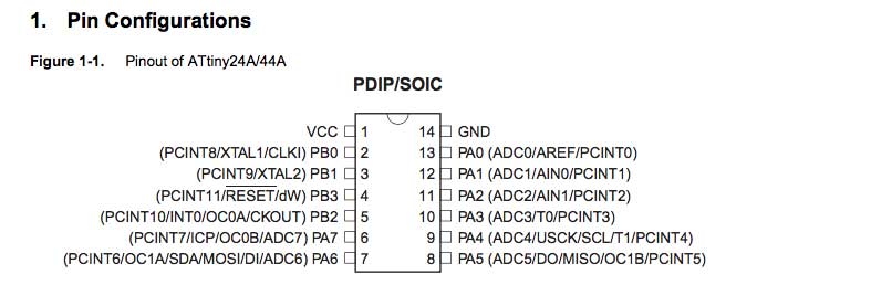
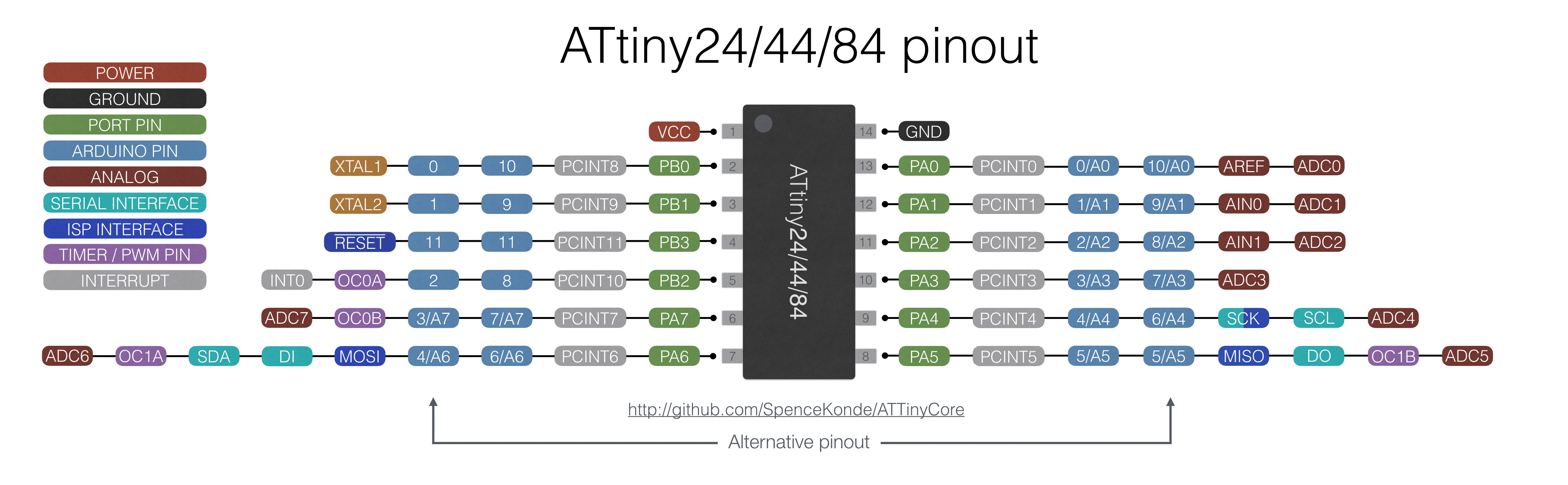
After a successful trial with the Arduino board, I am going to try with mine. First, I had to change the pins of the code. For this, I review the datasheet of the ATTiny 44 pins and the information from ATTinyCore and the design in Eagle of my board for the connection of the pins to work in Arduino.
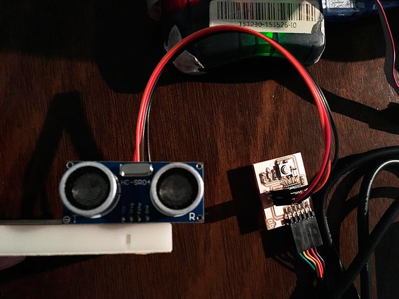
I use the ISP to connect the sensor:
- VCC to VCC
- GND to GND
- Trigger to SCK(3) in the ISP (that is connected to PA4(9) on the Attiny 44)
- Echo to MISO(1) (that is connected to PA5(8) on the Attiny44)
Attiny44 don’t have UART hardware, and I have to install it by software. First, I also have to check which pins of the attiny aloud the serial connection to my computer; the ones that allowed it are the TX in AIN0 an RX in AIN1. So I have to install a Software Serial.
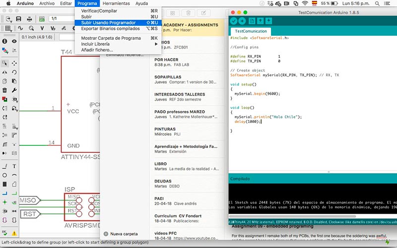
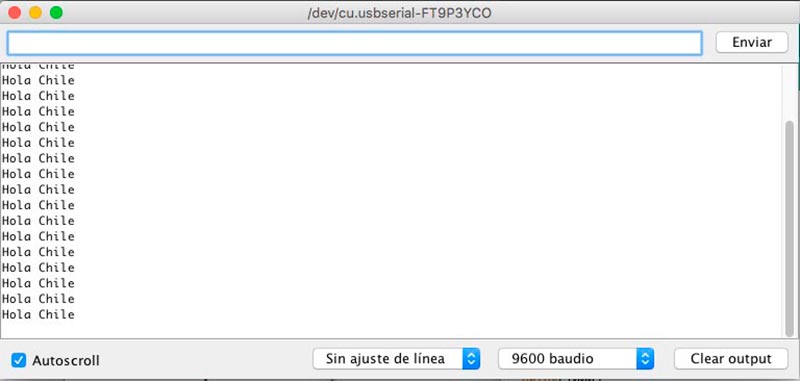
First, I write a code to test the serial communication, to know if I set the RX and TX pin right. The TX (0) (transmisión) of the PCB has to go to the RX (1) (reception) of the computer and, of course, the RX of PCB has to go to the TX of the computer. I load the code, but nothing happens in the serial, so I change the pins (TX to 1 and RX to 0), load the code again…and Works!
#include

//Config pins

#define RX_PIN        0
#define TX_PIN        1

// Create object
SoftwareSerial mySerial(RX_PIN, TX_PIN); // RX, TX

void setup()
{
  mySerial.begin(9600);
}

void loop()
{
  mySerial.println("Hola Chile");
  delay(1000);

}
*Because is not an Arduino PCB, I have to upload the code selecting “subir usando programador”.
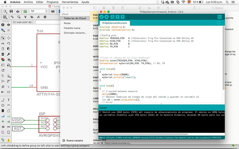
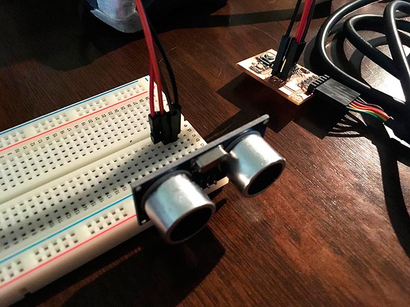
Second, I use the code that I create with the NewPing library, adding the mySerial connection. But the sensor didn’t measure any information.
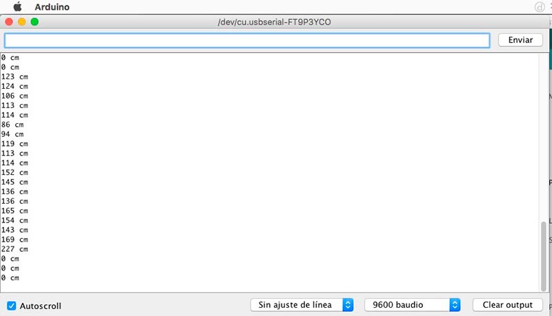
Third, I write code without a library, in case that was the problem, but the sensor still doesn’t measure anything. I was going to change the sensor when I realise that I had the connection wrong on the protoboard. So I correct that and finally the sensor Works!
#include

// VARIABLES FOR PINES
const int pinecho = 5;
const int pintrigger = 4;
const int pinled = 7;
#define RX_PIN        0
#define TX_PIN        1

// VARIABLES FOR CALCULATIONS
unsigned int tiempo, distancia;
SoftwareSerial mySerial(RX_PIN, TX_PIN); // RX, TX


void setup() {
  // PREPARE SERIAL COMMUNICATION
  mySerial.begin(9600);
  // CONFIG INPUT AND OUTPUT PINS
  pinMode(pinecho, INPUT);
  pinMode(pintrigger, OUTPUT);
  pinMode(pinled, OUTPUT);
}

void loop() {
  // SEND PULSE OF TRIP IN THE PIN "TRIGGER"
  digitalWrite(pintrigger, LOW);
  delayMicroseconds(2);
  digitalWrite(pintrigger, HIGH);
  // THE PULSE LASTS AT LEAST 10uS IN HIGH STATE
  delayMicroseconds(10);
  digitalWrite(pintrigger, LOW);

  // MEASURE THE TIME IN THE HIGH STATE OF THE PIN "ECHO" THE PULSE IS PROPORTIONAL TO THE DISTANCE MEASURED
  tiempo = pulseIn(pinecho, HIGH);

  // THE SPEED OF THE SOUND IS 340 M / S OR 29 MICROSECUNDS PER CENTIMETER
  // WE DIVIDATE THE TIME OF THE PULSE BETWEEN 58, TIME THAT IT TAKES TO TRAVEL RIGHT AND RETURN A CENTIMETER THE ONDA SONORA
  distancia = tiempo / 58;

  // SEND THE RESULT TO THE SERIAL MONITOR
  mySerial.print(distancia);
  mySerial.println(" cm");
  delay(200);

  // TURN ON THE LED WHEN IT IS COMPLIED WITH CERTAIN DISTANCE
  if (distancia <= 15)
  {
    digitalWrite(13, HIGH);
    delay(500);
  } else {
    digitalWrite(13, LOW);
  }
}
Because I re-use the board of Electronic Design Week, review my Networking Assignment for more details of design and fabrication of a board whit an input. Check my main board, where the inputs are the buttons through which I control the axes of the machine.

Este obra está bajo una licencia de Creative Commons Reconocimiento-NoComercial-CompartirIgual 4.0 Internacional.