Assignment 14_networking & communications
01 design and build a wired &/or wireless network connecting at least two processors
I am full filling this assignment the week of the develops of the final project. So, I am designing and fabricating my boards to control the movement of my axis X, Y and Z on my educational machine project.
--STEPPERS & DRIVERS--
For control the steppers I read this Instructable's tutorial to understand how I could control more than one stepper. This tutorial help to understand the connections, how steppers and the driver works.
For my machine, I am using a Unipolar Stepper Motor Step 7 Volt from Jameco.
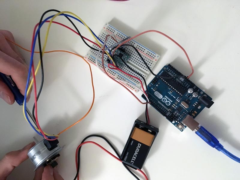
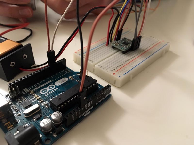
(PROTOTYPE WITH ARDUINO)
I use the code (C) and schematic of the connections with Arduino and the Stepper Motor Driver 288YJ-48 5v. The stepper start working, but without an input that controls it.
The code of the Instructable's tutorial wasn't enough to control the stepper with buttons. I use it and add the number of steps per revolution of my stepper: 48. I search this in the datasheet of my stepper.
CODE 1
/* Stepper Copal
 * -------------
 *
 * Program to drive a stepper motor coming from a 5'25 disk drive
 * according to the documentation I found, this stepper: "[...] motor
 * made by Copal Electronics, with 1.8 degrees per step and 96 ohms
 * per winding, with center taps brought out to separate leads [...]"
 * [http://www.cs.uiowa.edu/~jones/step/example.html]
 *
 * It is a unipolar stepper motor with 5 wires:
 *
 * - red: power connector, I have it at 5V and works fine
 * - orange and black: coil 1
 * - brown and yellow: coil 2
 *
 * (cleft) 2005 DojoDave for K3
 * http://www.0j0.org | http://arduino.berlios.de
 *
 * @author: David Cuartielles
 * @date: 20 Oct. 2005
 */

int motorPin1 = 8;
int motorPin2 = 9;
int motorPin3 = 10;
int motorPin4 = 11;
int delayTime = 50;

void setup()
{
  pinMode(motorPin1, OUTPUT);
  pinMode(motorPin2, OUTPUT);
  pinMode(motorPin3, OUTPUT);
  pinMode(motorPin4, OUTPUT);
}

void loop()
{
  digitalWrite(motorPin1, HIGH);
  digitalWrite(motorPin2, LOW);
  digitalWrite(motorPin3, LOW);
  digitalWrite(motorPin4, LOW);
  delay(delayTime);
  digitalWrite(motorPin1, LOW);
  digitalWrite(motorPin2, HIGH);
  digitalWrite(motorPin3, LOW);
  digitalWrite(motorPin4, LOW);
  delay(delayTime);
  digitalWrite(motorPin1, LOW);
  digitalWrite(motorPin2, LOW);
  digitalWrite(motorPin3, HIGH);
  digitalWrite(motorPin4, LOW);
  delay(delayTime);
  digitalWrite(motorPin1, LOW);
  digitalWrite(motorPin2, LOW);
  digitalWrite(motorPin3, LOW);
  digitalWrite(motorPin4, HIGH);
  delay(delayTime);
}
CODE 2
 /*     Simple Stepper Motor Control Exaple Code
 *
 *  by Dejan Nedelkovski, www.HowToMechatronics.com
 *
 */
// defines pins numbers
const int stepPin = 3;
const int dirPin = 4;

void setup() {
  // Sets the two pins as Outputs
  pinMode(stepPin,OUTPUT);
  pinMode(dirPin,OUTPUT);
}
void loop() {
  digitalWrite(dirPin,HIGH); // Enables the motor to move in a particular direction
  // Makes 200 pulses for making one full cycle rotation
  for(int x = 0; x < 48; x++) {
    digitalWrite(stepPin,HIGH);
    delayMicroseconds(100);
    digitalWrite(stepPin,LOW);
    delayMicroseconds(100);
  }
  delay(1000); // One second delay

  digitalWrite(dirPin,LOW); //Changes the rotations direction
  // Makes 400 pulses for making two full cycle rotation
  for(int x = 0; x < 96; x++) {
    digitalWrite(stepPin,HIGH);
    delayMicroseconds(100);
    digitalWrite(stepPin,LOW);
    delayMicroseconds(100);
  }
  delay(1000);
}
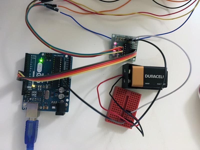
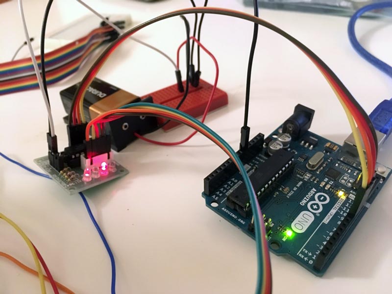
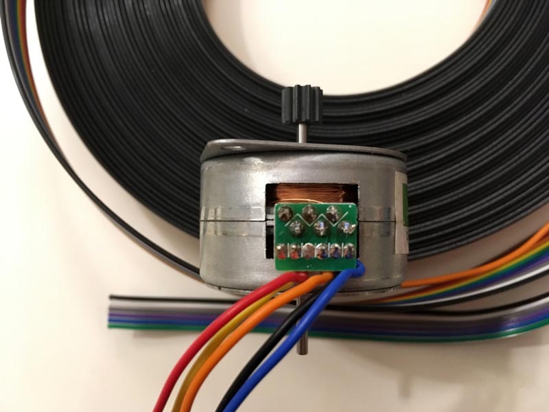
For control the stepper with the A4988 I hack my stepper from 5 wire (and unipolar) to 4 wire (and bipolar). For hacking the stepper, I follow the instructions of stargazerslounge's web, and I cut the connection of the orange cable to the stepper.
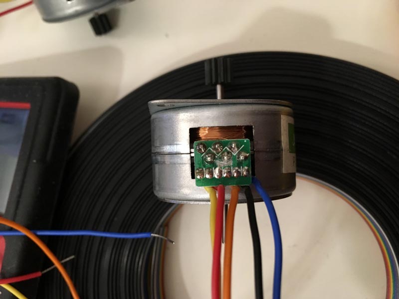
This work great, and I could control the steppers with the drivers A4988 I bought. For work with this driver, I download the A4988 library for Arduino.
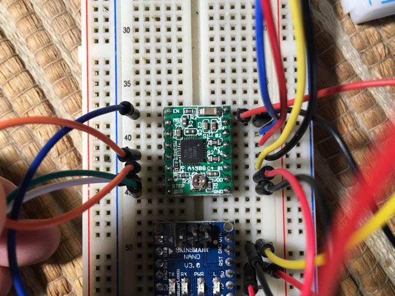
I am not going to use the micro step for my machine, so I am only using the pins of Direction, Step and Enable.
For this first try, I am powering each stepper with a 9V battery, because the 5V of Arduino is not enough to move the motors. Probably, at the final project, I am powering the nodes from the main board.
--BOARD DESIGN--
First, I have to understand what I need for all the machine works. So, I need:
INPUTS & OUTPUTS
- 2 steppers for Y-axis (because is an MDF machine y prefer to use stepper on both sides, to move more accurately)
- 1 stepper for X-axis
- 1 mini servo for Z-axis
- Buttons to control my axis.
COMPONENTS
Been the basics defined, I establish what is going to be on every board:
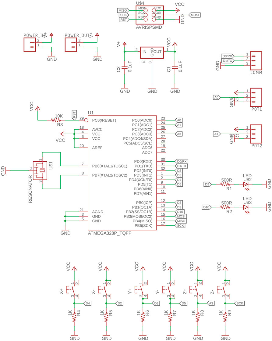
Bill of Materials_Main Board:
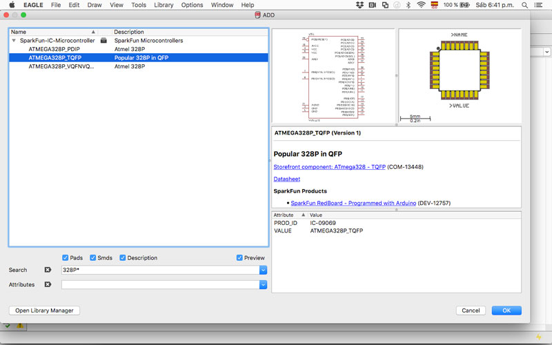
- 1 Microcontroller Atmega 328P
- 6 Buttons
- 2 LEDs red 1206
- 2 resistance 499Ohm 1206
- 6 resistance 1 K 1206
- 1 resistance 10K 1206
- 1 resonator / Crystal 20mhz
- 3 pin head 1x3
- 1 regulator sot23-3 5V
- 2 capacitor 0.1uF 1206
- 1 ISP 2x3
- 2 terminal block 3.5mm
For test the microcontroller, I compile an Arduino test code of the stepper to attiny45 to know it would fit in the microcontroller, but uses 123% of the space, is too big. I compile also in the attiny85 use 61% of the space.
The ideal microcontroller to my boards is the attiny85 because the amount of space is big enough and is cheap. But we don’t have it in the inventory of Fab Lab Stgo. I search If I could buy it but they would arrive in a week, and I need to advance with my final project.
So, finally, I decide to use the atmega328 microcontroller (32K and 32 pins). Atmega238 have enough space, but a lot of more pins (could be a good thing to add some LEDs) but is more expensive. So I decide to use it, for this assignment, because we have in the Fab Lab Santiago (save time) and have enough space for the code, but probably is going to be a challenge to solder to the board (I'm still working on my soldering skills).
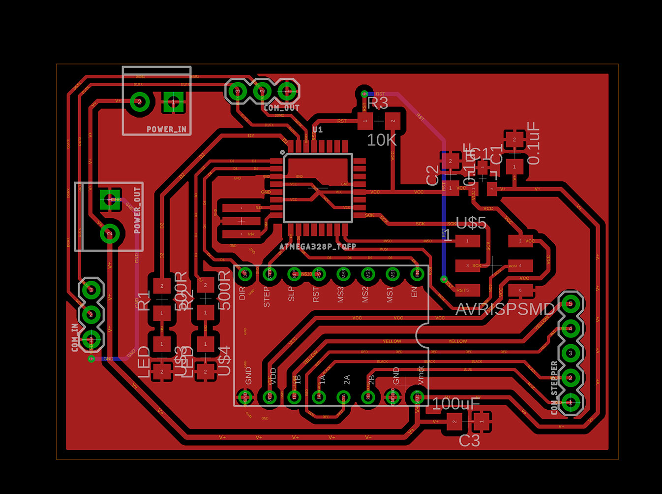
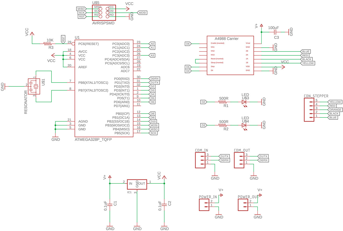
Bill of Materials_Node Board:
*For this board I need two board to be the same, but the third one adds an extra 3x1 pinhead connector for the micro servo.
- 1 Microcontroller Atmega 328P
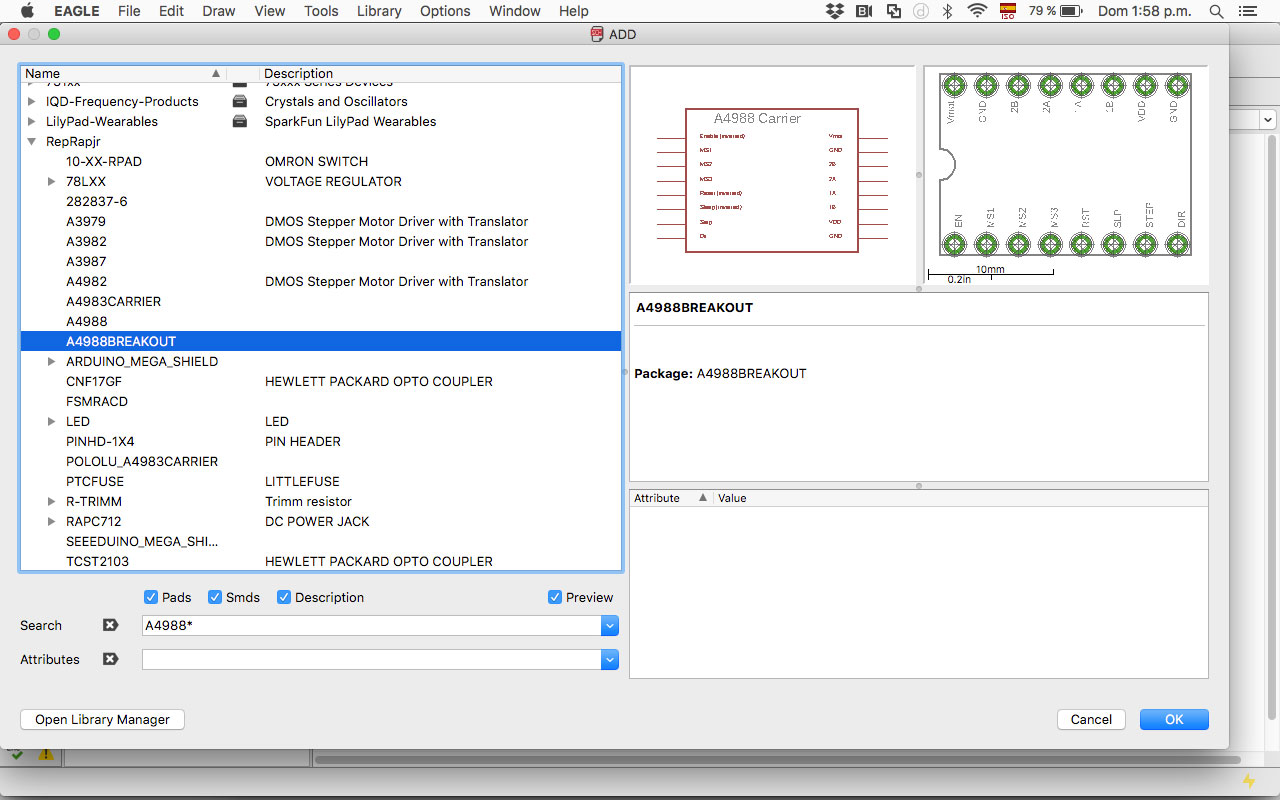
- 1 Driver A988
- 2 LEDs red 1206
- 2 resistance 499Ohm 1206
- 1 resistance 10K 1206
- 1 resonator / Crystal 20mhz
- 1 pin head 1x5
- 2 pin head 1x3
- 1 regulator sot23-3 5V
- 2 capacitor 0.1uF 1206
- 1 capacitor 10uF 1206
- 1 ISP 2x3
- 2 terminal block 3.5mm
For creating the PCBs I download RepRap library for Eagle, to be able to add the A4988 to my schematic in Eagle.
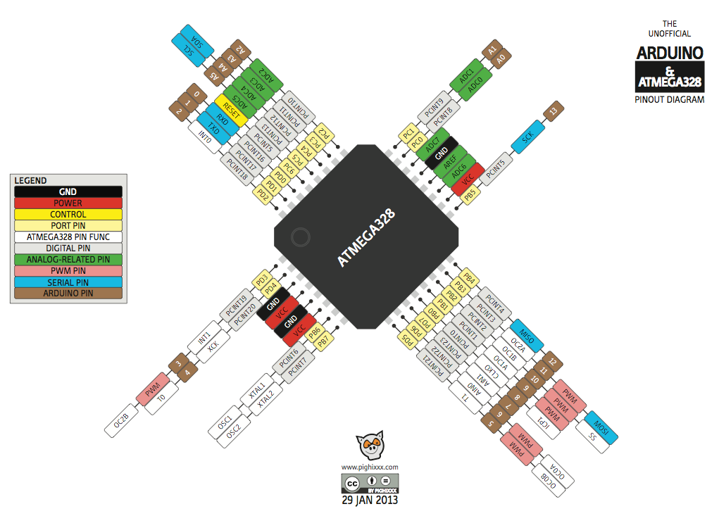
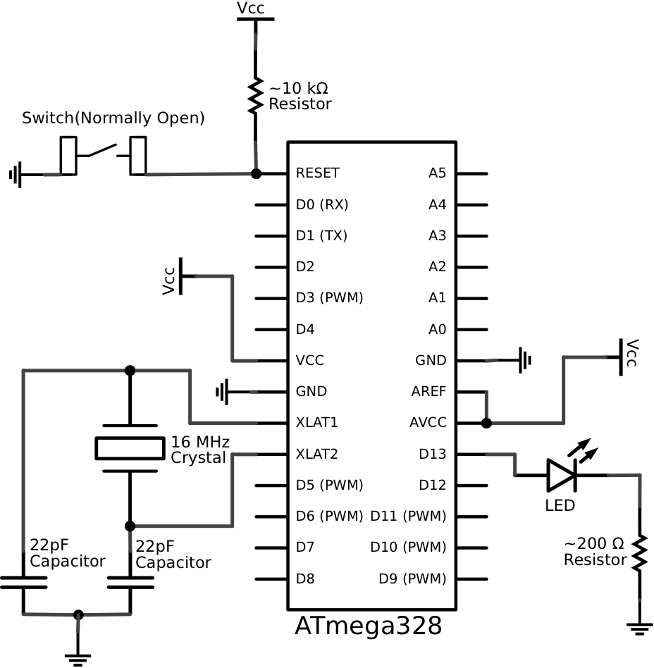
I also search the microcontroller 328p Arduino pinout for understanding where to connect the components and the Arduino schematic.
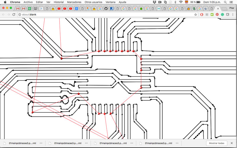
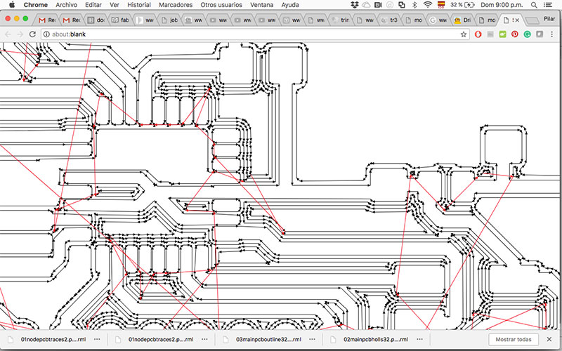
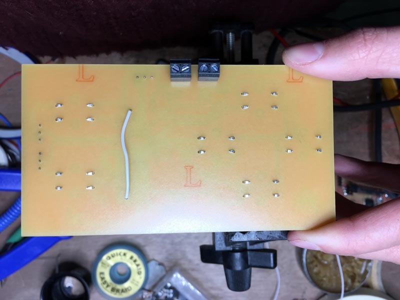
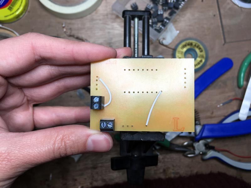
It was a real challenge that everything fit on the board and designing the traces. I have a bad time connecting the RST pin of the ISP with the microcontroller pin, but finally, I add an external cable to connect it.
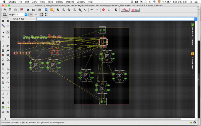
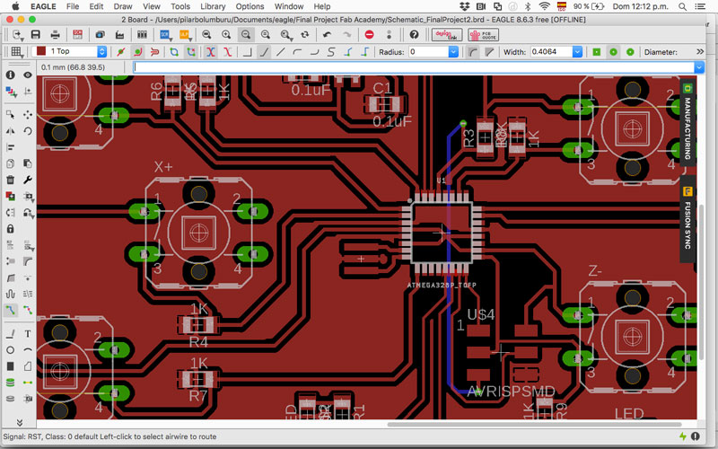
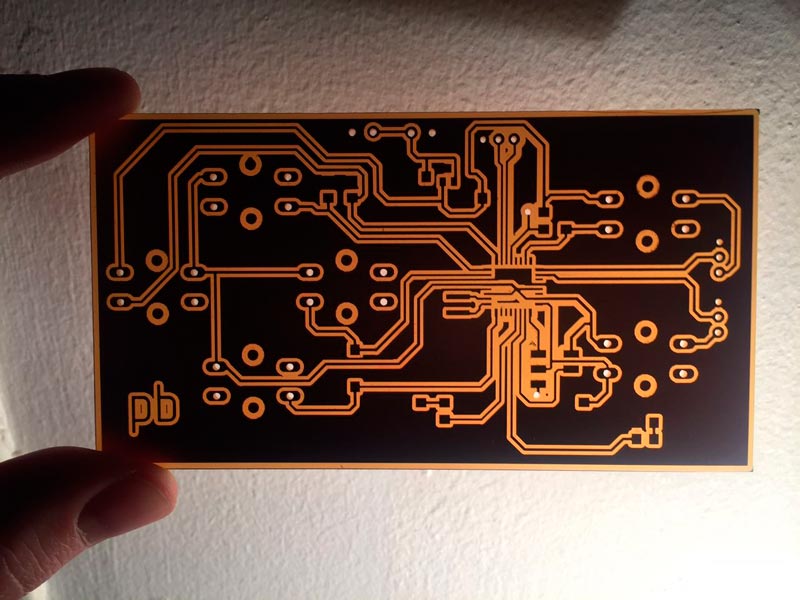
FINAL MAIN BOARD

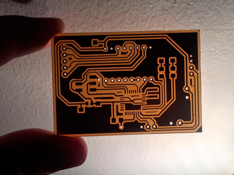
FINAL NODE BOARD
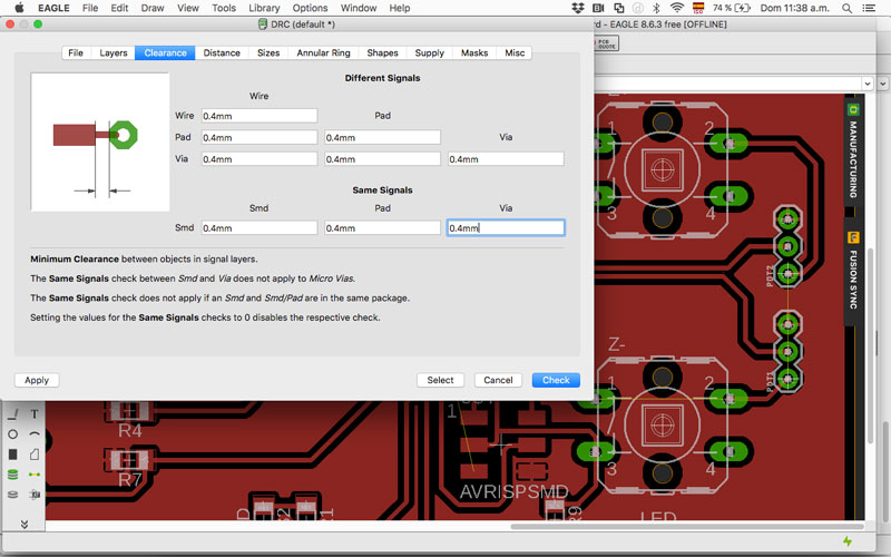
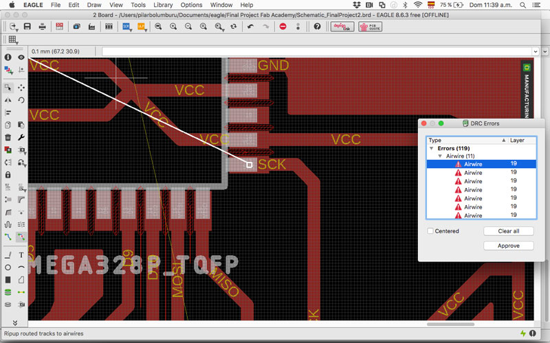
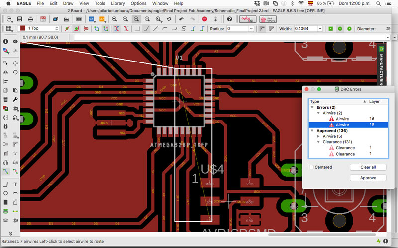
I generate the png and fix it in Photoshop. I had to be especially careful with the thickness of the microcontroller paths because when I run the image in mods, the route that creates don´t separate the paths.
I tried to increase image quality and change the settings to a smaller diameter (but it went from 0.4 to 2.4 mm to could read the different paths, which was going to harm the final fabrication of the PCB because the traces were going to be thicker). Finally, I edit the image in Photoshop and reduce the paths. It works! Perhaps the ideal would be to modify it from Eagle to change the paths there.
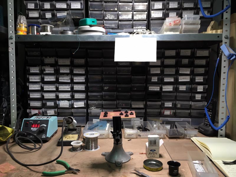
--MAKING BOARDS--
My first try at routing the traces I realize I export wrong the file in mods, and the board was bad escalated.
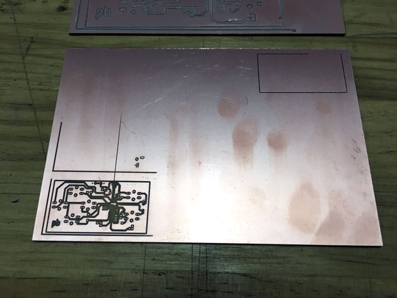
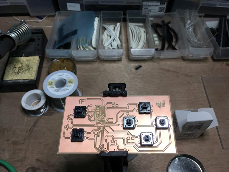
My second time the size was right, but the end mill that was on the machine was it had no edge, so the result was this:
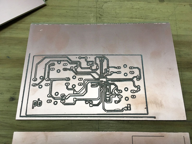
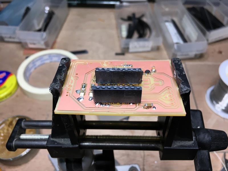
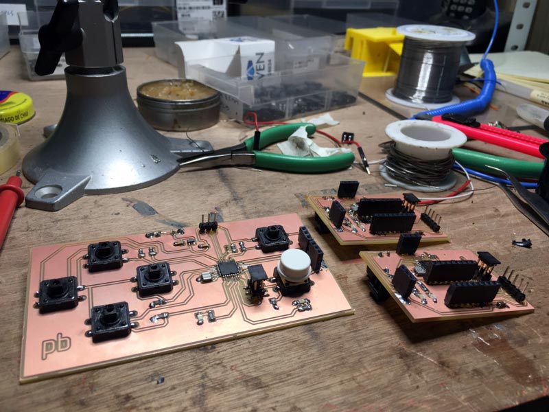
Final boards:
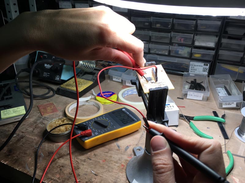
For soldering, applying what I learn from my previous experiences, I was very methodic to test with the multimeter every connection I solder. This help to "debug" the solder mistakes at the same time I was fabricating the boards. Soldering the microcontroller was the biggest challenge because the paths are very small and the paths of the board to solder were more small than usual for editing the image in Photoshop for mods.
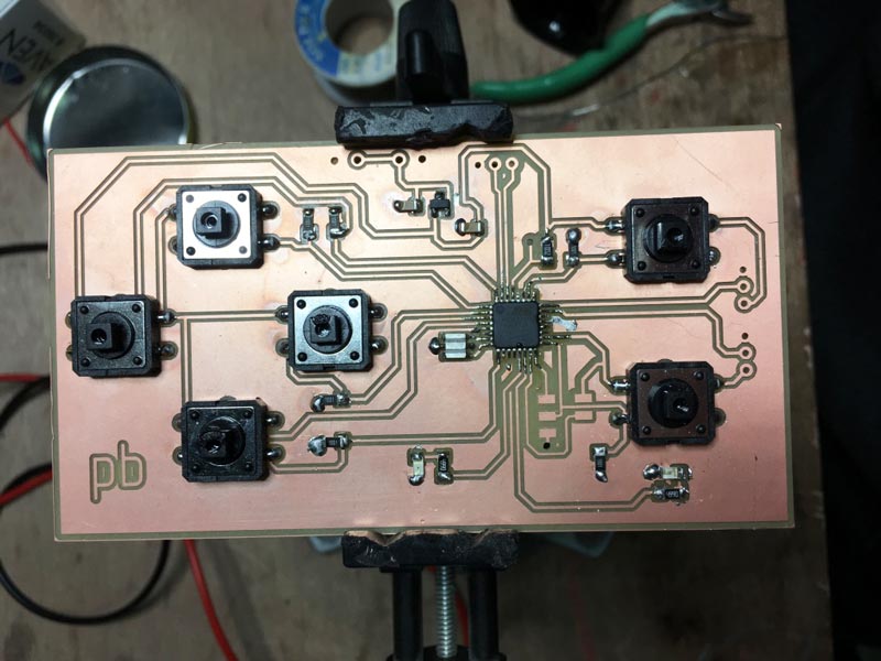
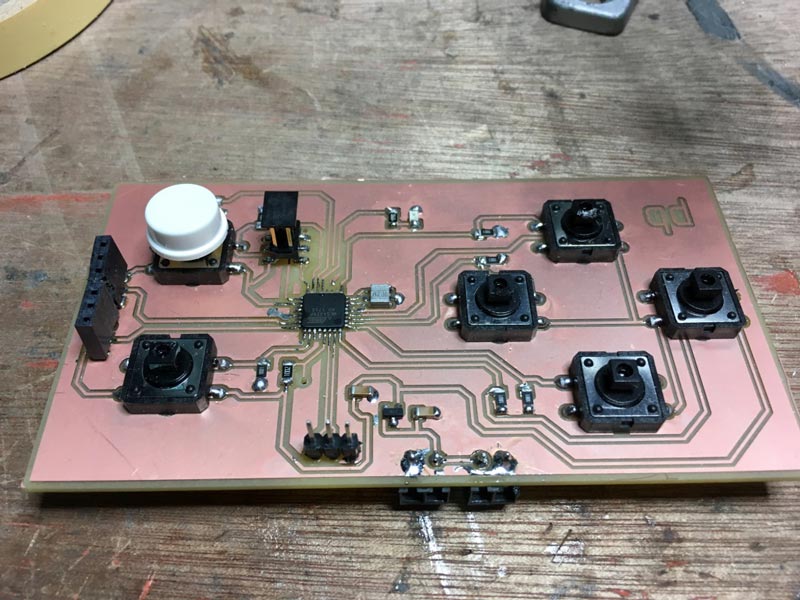
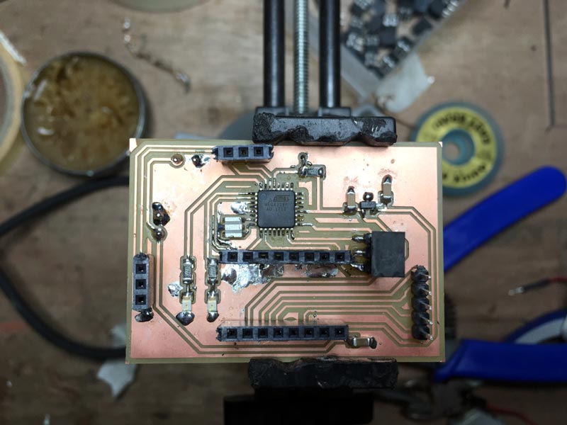
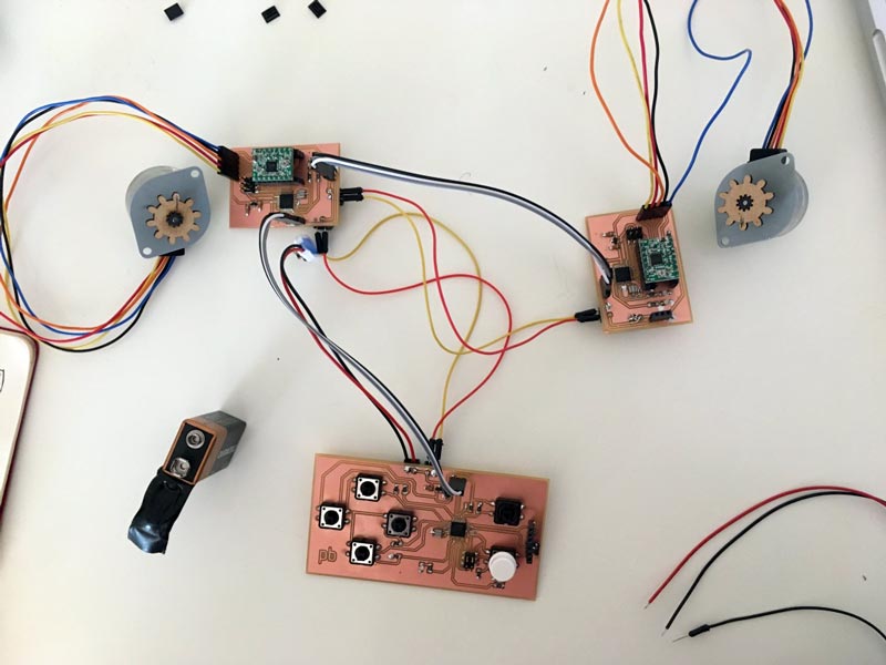
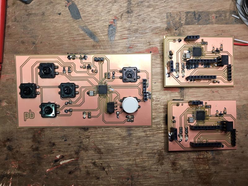
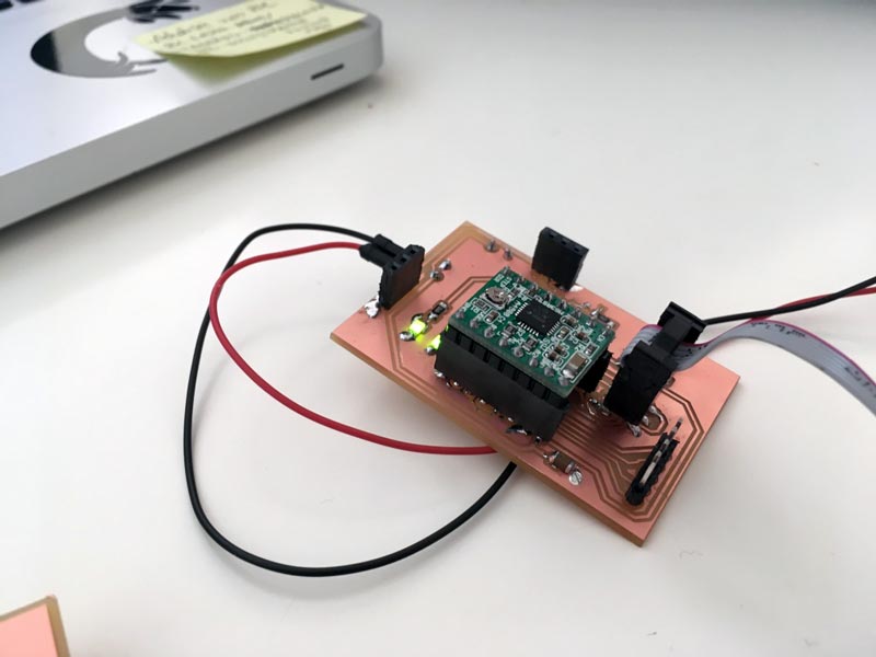
I end up with my main board and the three node boards, one of this has an extra connector for the micro servo of the Z-axis.
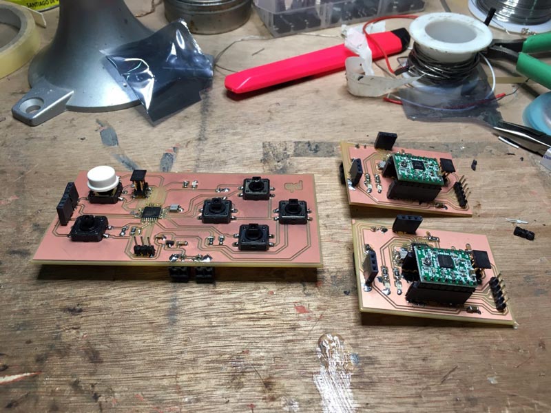
Once I had all the boards fabricated I connected the TX and RX of every board, and the power of the board adding an extra 9V battery per stepper for the first test.
For the final project, I am powering the machine with an electric power converter of 9V.
--PROGRAMMING BOARDS--
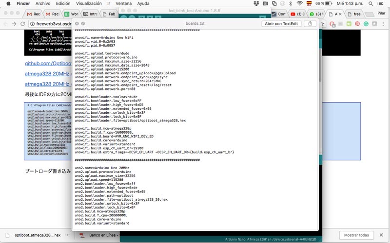
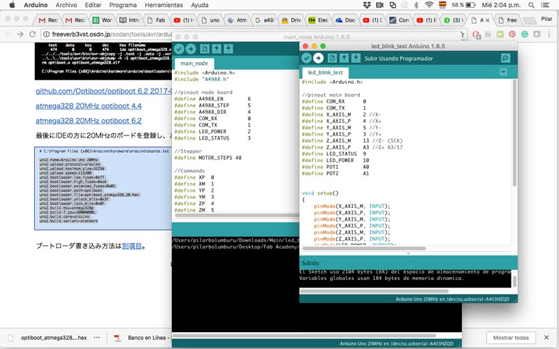
The first problem was that a typical Arduino PCB have a crystal of 16Mhz, but I am using on my boards a 20Mhz crystal. Because I am using the library of Arduino, we need to change this detail so the clock will be accurate.
I need to:
- The bootloader is configured in 20Mhz to communicate to the board with the same clock, for don’t have problems there.
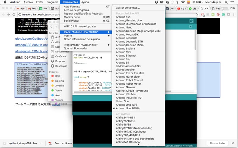
- I have to create a file of configuration of the board of Arduino to also the Arduino IDE “understand” that we are working at 20Mhz.
Working with steppers makes very important to manage the clock of the PCB, for this, I follow the instruction of the freeverb3vst's website where explain how to create a new type of Arduino board with a 20mhz crystal to be recognized it in the Arduino IDE.
For programming the board I download the Stepper Driver library for Arduino.
First, I test if the boards work OK and the configuration of the clock was ok I run a test code using the led of the board to turn on and off in one second. It works well.
Download Test Code for Main Board
Download Test Code for Node Board
Then, I load the following code to the main board:
include

//pinout main board
#define COM_RX      0
#define COM_TX      1
#define X_AXIS_M    2 //X-
#define X_AXIS_P    4 //X+
#define Y_AXIS_M    5 //Y-
#define Y_AXIS_P    3 //Y+
#define Z_AXIS_M    13 //Z- (SCK)
#define Z_AXIS_P    A3 //Z+ A3/17
#define LED_STATUS  9
#define LED_POWER   10
#define POT1        A0
#define POT2        A1

//commands
#define XP  '0' //X+ Plus
#define XM  '1' //X- Minus
#define YP  '2' //Y+
#define YM  '3' //Y-
#define ZP  '4' //Z+
#define ZM  '5' //Y-


void setup()
{
    pinMode(X_AXIS_M, INPUT);
    pinMode(X_AXIS_P, INPUT);
    pinMode(Y_AXIS_M, INPUT);
    pinMode(Y_AXIS_P, INPUT);
    pinMode(Z_AXIS_M, INPUT);
    pinMode(Z_AXIS_P, INPUT);
    pinMode(LED_POWER, OUTPUT);
    pinMode(LED_STATUS, OUTPUT);
    pinMode(COM_TX, OUTPUT);
    pinMode(COM_RX, INPUT);
    Serial.begin(9600);
    digitalWrite(LED_POWER, HIGH);
    pinMode(COM_TX, INPUT); //configures tx as input so the communication bus is open and other nodes can connect
}

void loop()
{
    if (digitalRead(X_AXIS_P))
    {
        //X+
        pinMode(COM_TX, OUTPUT);
        Serial.print(XP);
        Serial.flush();
        pinMode(COM_TX, INPUT);
    }

    if (digitalRead(X_AXIS_M))
    {
        //X-
        pinMode(COM_TX, OUTPUT);
        Serial.print(XM);
        Serial.flush();
        pinMode(COM_TX, INPUT);
    }

    if (digitalRead(Y_AXIS_P))
    {
        //Y+
        pinMode(COM_TX, OUTPUT);
        Serial.print(YP);
        Serial.flush();
        pinMode(COM_TX, INPUT);
    }

    if (digitalRead(Y_AXIS_M))
    {
        //Y-
        pinMode(COM_TX, OUTPUT);
        Serial.print(YM);
        Serial.flush();
        pinMode(COM_TX, INPUT);
    }

    if (digitalRead(Z_AXIS_P))
    {
        //Z+
        pinMode(COM_TX, OUTPUT);
        Serial.print(ZP);
        Serial.flush();
        pinMode(COM_TX, INPUT);
    }

    if (digitalRead(Z_AXIS_M))
    {
        //Z-
        pinMode(COM_TX, OUTPUT);
        Serial.print(ZM);
        Serial.flush();
        pinMode(COM_TX, INPUT);
    }

    delay(200); //debounce delay
}
The code for the node board is the same for all, but I comment the "define" depending which pcb I am programming:
- YAXIS_P : Board of Y-axis of the right
- YAXIS_M: Board of Y-axis of the left
- XZAXIS: Board of X-axis and Z-axis (micro servo)
include
#include "A4988.h"
#include

//pinout node board
#define A4988_EN        6
#define A4988_STEP      5
#define A4988_DIR       4
#define SERVO_PIN       10
#define COM_RX          0
#define COM_TX          1
#define LED_POWER       2
#define LED_STATUS      3

//Stepper
//#define YAXIS_P
#define YAXIS_M
//#define XZAXIS
#define MOTOR_STEPS 48 //adjust steps if needed

//Commands
#define XP  '0' //X+
#define XM  '1' //X-
#define YP  '2' //Y+
#define YM  '3' //Y-
#define ZP  '4' //Z+
#define ZM  '5' //Z-

A4988 stepper(MOTOR_STEPS, A4988_DIR, A4988_STEP, A4988_EN);
Servo zServo;

void toggleLed(int led)
{
  digitalWrite(led,!digitalRead(led));
}

void setup()
{
    pinMode(LED_POWER, OUTPUT);
    pinMode(LED_STATUS, OUTPUT);
    pinMode(A4988_EN, OUTPUT);
    pinMode(A4988_STEP, OUTPUT);
    pinMode(A4988_DIR, OUTPUT);
    pinMode(SERVO_PIN, OUTPUT);
    Serial.begin(9600);
    digitalWrite(LED_POWER, HIGH);
    digitalWrite(LED_STATUS, LOW);
    digitalWrite(SERVO_PIN, LOW);
    pinMode(COM_TX, INPUT); //configures tx as input so the communication bus is open and other nodes can connect

    stepper.begin(20, 1); //15rpm full step
    stepper.disable(); //disable stepper driver
    //stepper.move(10);

    #ifdef XZAXIS
    zServo.attach(SERVO_PIN);
    //zServo.write(120);
    #endif
}

void loop()
{
    char cmd_read;
    if (Serial.available())
    {
      cmd_read = Serial.read();
      toggleLed(LED_STATUS);
      //digitalWrite(LED_STATUS, HIGH);

      #ifdef YAXIS_P
        if (cmd_read == YP)
        {
            stepper.enable();
            stepper.move(5);
            stepper.disable();
        }
        else if (cmd_read == YM)
        {
            stepper.enable();
            stepper.move(-5);
            stepper.disable();
        }
      #endif


      #ifdef YAXIS_M
        //inverted Y AXIS
        if (cmd_read == YP)
        {
            stepper.enable();
            stepper.move(-5);
            stepper.disable();
        }
        else if (cmd_read == YM)
        {
            stepper.enable();
            stepper.move(5);
            stepper.disable();
        }
      #endif


      #ifdef XZAXIS

        if (cmd_read == XP)
        {
            stepper.enable();
            stepper.move(5);
            stepper.disable();
        }
        else if (cmd_read == XM)
        {
            stepper.enable();
            stepper.move(-5);
            stepper.disable();
        }

        if (cmd_read == ZP)
        {
            zServo.write(90);
        }
        else if (cmd_read == ZM)
        {
            zServo.write(130);
        }
      #endif
    }
}
For testing the Z-axis mechanism with the micro servo, I prototype with Arduino the connections and the code, for exploring which was the angle I need for my Z be up and down. This was the code:
//Teste Z-axis mechanism

//zoomkat servo button test 12-29-2011
// Powering a servo from the arduino usually *DOES NOT WORK*.

#include
int button1 = 2; //button pin, connect to ground to move servo
int press1 = 0;
int button2 = 3; //button pin, connect to ground to move servo
int press2 = 0;
Servo servo1;

void setup()
{
  pinMode(button1, INPUT);
  pinMode(button2, INPUT);
  servo1.attach(9);
  digitalWrite(2, HIGH); //enable pullups to make pin high
  digitalWrite(3, HIGH); //enable pullups to make pin high
}

void loop()
{
  press1 = digitalRead(button1);
  if (press1 == LOW)
  {
    servo1.write(90);
  }

  press2 = digitalRead(button2);
  if (press2 == LOW)
  {
    servo1.write(130);
  }
}
The following photos and video is the first test of the main board and two of the node board, one for X-axis (X buttons) and one for Y-axis (Y buttons).
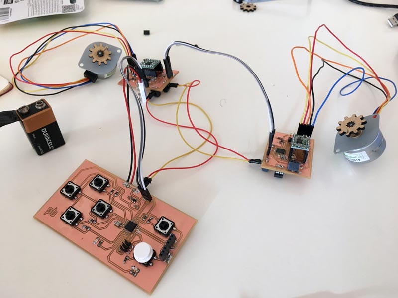
This works excellent (and fulfils the Networking Assignment for week 14), I learn a lot of the hardware and software of a board. Especially, that having the hardware planned and fabricated very carefully and methodically, it would save you a lot of problems, because is more easy to change and adapt the code than to look for mistakes in both subjects.
Another subject I learn that is very important to think at the beginning of the power need of every component. I have a real hard time trying to understand why the micro servo wasn't working, and at the end was that the regulator SOT 23-3 5V that I add in the boards deliver 100mA, but the micro serve need it 550 mA. Finally, for this version, I connect the micro servo apart to 5V and then I connect 3 batteries of 9V in parallel (to triple the capacity but not the voltage) to the main board, that power the steppers.
FUTURE LEARNINGS
For the future development of the project, I have to redesign how the servo is connected to the power, and also explore more option to power all the machine.
*To see the final project integrated go to Mechanical & Machine Assignment

Este obra está bajo una licencia de Creative Commons Reconocimiento-NoComercial-CompartirIgual 4.0 Internacional.