

WEEK 12
Output Devices
Equipment
- Hardware: Roland Mill
- Software: VPanel, Arduino IDE
- Material: PCB Board, RGB Leds
RGB LED
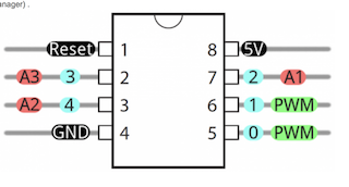
I made an RGB LED board for output week. The LEDs are connected to pins on the ATTiny that have PWM functionality. Pulse Width Modulation allows for an analog output by controlling the percentage of the duty cycle that the 5V is being sent. By lowering the percentage of time that the LEDS are on, they will appear dimmer. Values on the PWM scale can range from 0-255 with 255 being 100% of the duty cycle. We will send PWM values to each indvidual RGB pin to achieve a spectrum of colors.Board Production
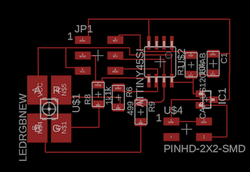
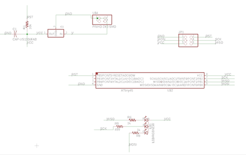
Eagle Design
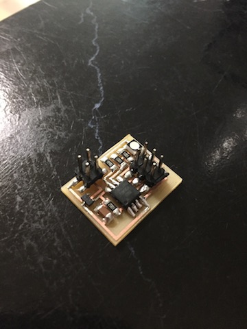
Milled & Soldered
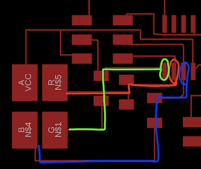
RGB Leds have 4 pins- each color has a designated pin on the AtTiny and an anode or cathode pin depending on the LED. For this board, the leds are connected to pins 5, 6, 7 (Arduino IDE 0, 1, 2) and the Anode connected to power.
RGB Leds require
Programming
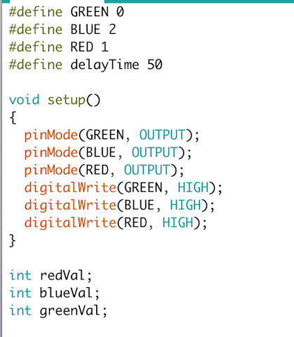
void set up
Since we are using Common Anode LED, we need to pull the pins on the ledpins as HIGH to turn them on. If using Common Cathode, pins are pulled LOW.Define int for each color which we will use to change the brightness which will result in color changes
void loop
The loop will start with Red set to the highest brightness and blue and green turned down to 0. As the red light decreases in brightness, the green light will increase in brightness inversely until the red is 0 and green is 255. It will then cycle through the same function for the green and blue led.NEOPIXEL RING
Board Design
Unlike the RGB Led which requires separate pins for each color, neopixels only need a single DI pin plus Ground and Power. You can also program individual leds to make animations and there are extensive libraries for the neopixels that offer a range of colors and sketches. I referenced Adafruit's Neopixel Uberguide to find out more about how to use the ring. They recommend a large capacitor (1000uf for 6.3 V+) across ground V to prevent large surges of power that may damage the neopixels, and a 300-500 ohm resistor from the microcontroller's data pin to the data input of the Neopixel ring for clean communication. Each Neopixel draws a maximum of 60 milliamps when set to full brightness. They can be run on a 5V DC power supply or a 3.7V Lithium polymer battery.The data transmission is self clocking, sending a clock pulse along with the data on a single shared line. It uses a Non Return to Zero communication mode. NRZ is a when the ones and zeros in the code are represented with high or low voltages, never settling at zero between bit transfers. Each individual neopixel is connected to the main circuit by 5 pins: Data In, Data Out, Circuit power supply, LED power supply and ground. Data is sent in 3 bytes, 8 bits for each color in the sequence of Green, Red, Blue. The microcontroller sends data to the first pixel, then sets the data line on low for at least 50microseconds while it is sent to a latch. A latch is a circuit with two inputs (set and reeset) and one output. The output will respond to the set input and will hold the signal high or low depending on the type of latch, until triggered by the reset input. The datasheet mentions something about an 'internal signal reshaping amplification circuit' but I couldn't find anything on the internet about what this exactly is. The data is then sent down the pixel line through the Data Out port.
Eagle
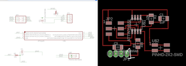
Components List
- ATTiny 45
- 10k Resistor
- 1uf Cap
- 1k Cap
- 488 Res
- 2x2 Pin
- 2x3 Pin
Programming
Download the Adafruit NeoPixel Library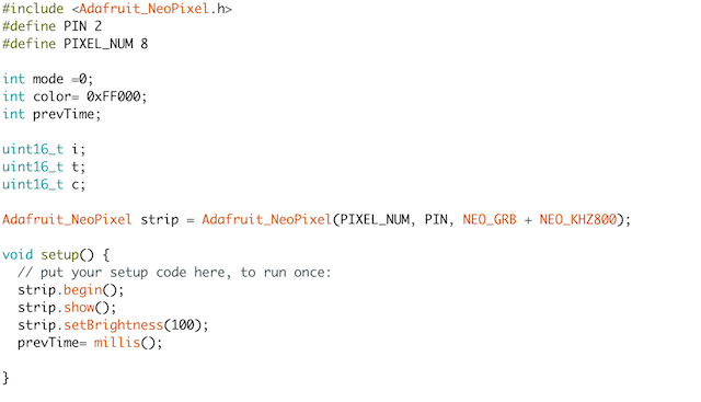
Libraries & Defining
define variablesInclude the
Name the Neopixels by Adafruit_NeoPixel Give_Name = Adafruit_NeoPixel(No. of Pixels, Pin No., Type of Neopixels Strip is the name that we will give to our Neopixels.
void set up()
strip.begin(): sets up the neopixels to be the output data strip.show(): sets the neopixels to off upon startingvoid loop()
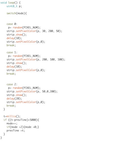
switch(mode): this will switch through various given set ups. Here, it will switch through different colors.We set an unsigned integer of 8 bits p to be a RANDOM selection of any number upto our pixel count, which is 8.
strip.setPixelColor(pixel #, RValue, GValue, BValue): set the random p to a color based on R, G, B Values up to 255 each
There will be a delay, then the pixel will go off. It will then select another random p, and repeat the commands. After 5 seconds, it will move on to the next case(color)
If the time of one case goes over 5000 milliseconds, then it will go on to the next mode. When it gets to the last case(mode>2) it will return back to the first mode(mode=0).