

WEEK 14
Networks & Communication
Equipment
- Hardware: Roland Mill
- Software: VPanel, Eagle, Arduino IDE, Git bash
- Material: RGB Led, PCB Board
Serial Communication
Asynchronous
Asynchronous communication send and receive digital pulses at an agreed upon rate of transfer. Devices do not send out clock signals because each unit will be set to the same timing prior to communication. Full duplex communication refers to the ability of both devices being simultaneously transmitters and receivers of data, half duplex means that only one device is allowed to communicate at a time. Data is communicated via 2 lines, RX for receiving and TX for transmitting. Devices will also share a common ground.I2C: Inter Integrated Circuit
This is a synchronous protocol set to the clock signal established by the master. It uses 2 wires SCL (clock) and SDA (data). It utilizes addressing of devices and can support up to 1008 slave devices. It also has something called a multi master system in which multiple masters are able to communicate with other devices. Downside is that it takes up a lot of room on a PCB because it needs pull up resistors for the slave devices and is slower than SPI.SPI: Serial Peripheral Interface
SPI is what we have been using to upload a bootloader from our fabISP to our boards. Unlike the UART, SPI is a synchronous form of communiction with a designated clock signal. The master board sends out a clock signal, and for each pulse it will send out one bit to a slave board (MOSI-Master out, slave in), while also receiving a bit from the slave board (MISO- Master in, slave out). Slave select with single out an indication to a specific slave device to be ready to recieve/send data. A disadvantage of the SPI is that it required many connections lines to communicate and only the master is able to control the communication so slaves are unable to communicate directly with each other.USB: Universal Serial Bus
Data communication is transferred in packets that composed of 8 bit bytes and is a very fast form of communication. There are two data pins, ones for transmitting and receiving.br/>CAN: Controller Area Network
CAN communication uses two wire (CAN_H and CAN_L) for data transmission and is half duplex, operating in real time. In CAN Communication, multiple devices are able to communicate with each other absent of a host computer. It does not use an addressing scheme but rather the nodes each have unique IDs which also support designating prority.Asynchronous Serial Bus
-
This week's assignment was to establish communication between multiple boards. I chose to make the serial bus consisting of a bridge board and 2 nodes based on asynchronous communication. The bridge and node boards communicate with each other via two wires Rx and Tx. The bridge board has an extra pin header for serial communication with the FTDI.
-
Download C code and make file
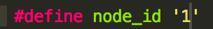
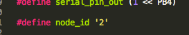
C Code < Create Unique IDs for each board
Each board needs a unique node id so that the bridge can call on You can assign each board an ID by changing the the C Code.
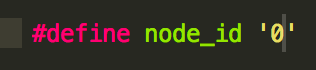
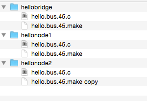
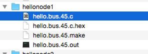
For sake of organization, I created a folder for each board containing both the Make file and C Code with the respective Node ID.
Make File
The serial bus is based on an RS232 asynchronous communication protocol, with the boards set to a speed of 9600 bauds. RS232 is a standard protocol that defines communication signals between the DTE(Data Terminal Equipment), which is the computer and the DCE(data Communication Equipment), the boards. It sets specifications for voltage levels, pins, signal levels among others.
Serial Data In is PB3, and serial data Out is PB4. The computer will send a start bit through the FTDI onto the bus to all boards via the Tx line, flashing all boards. This will indiciate to the other boards to be ready to receive data. It will then send one bit at a time to all boards on the Tx. If the node that is called upon recognizes it has been IDed, it will flash again, and then 'take over' the Rx line, sending the character back to the computer which will show up as 'node #' in our serial monitor. After it has sent the data, it will close its PB4 port and be ready for receiving data again on the serial bus.
Programming
-
Connect Bridge Board & FTDI to Programmer.
-
Run make
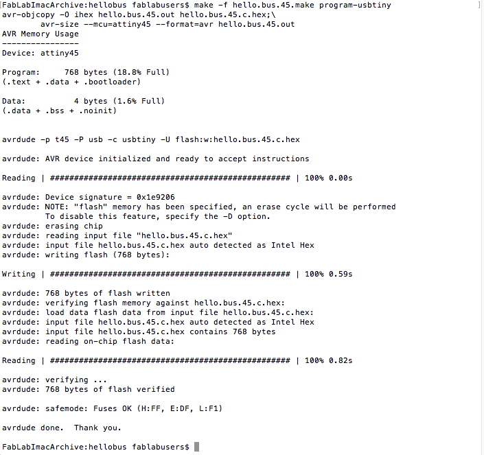
Using Bash, cd to Bridge board folder. Run command make -f hello.bus.45.make program-usbtiny since we are using a USBTiny to program the boards

If successful you should get the following message. This should also create a .out file and .hex file inside the bridge folder.
-
Program Nodes
Disconnect the bridge & FTI, and connect node boards individually to programmer. Repeat the make command to program node boards.
Serial Monitor in Arduino IDE
With the bridge board, FTDI and nodes all connected, open the serial monitor using Arduino IDE. In our serial monitor, we can type the node ID (0,1,2) that we wish to call. All the boards should flash once, and then the IDed node will flash again. You should then see the computer return "node#".Programmed Boards
Troubleshooting
Error messages
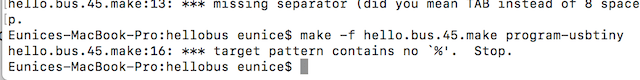
I would get error messages that read: Missing Seperator and/or target Pattern contains %. Stop.
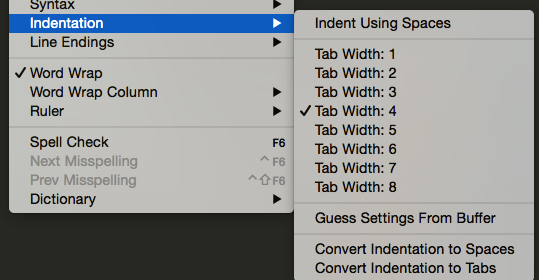
I found that sometimes the code can't be read if it is written with spaces instead of tabs. In Sublime text, under view, make sure that you are indenting using tabs rather than spaces. Go into the make file, delete indentations that were previously there, and replace with tab indentations.
Error: Cannot find find USB
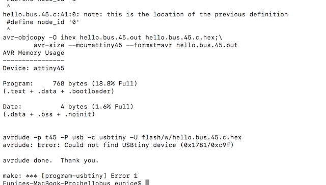
This means that there is something wrong with the connections on my board. I checked the node connections and my soldering looked ok. I compared it to the other node which was working fine, and it noticed that the design was different.
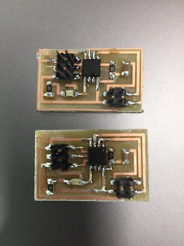
If you look closely, you can see that in n2, the resistor runs over an additional connection. I thought I had cut out the same board as N1, but I guess I had cut out a previous design. I had made so many corrections, that it got mixed up.