

WEEK 5
Electronics Production
Equipment
- Hardware: Roland RM20
- Software: Fabmodules, VPanel, BashTerminal
- Material: Copper PCB board
Fab Modules
I used Brian's FabTinyISP design.

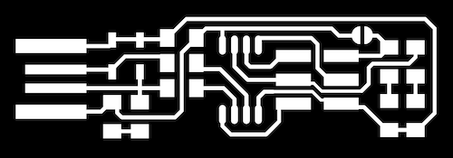
Download both trace & outline files.
Creating STL file using FabModules
Go to Fab Modules
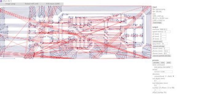
Trace Files
Input: Select png and find ISP traces file
Output: Roland mill (.rml)
Process: PCB trace (1/64)
Offset from origin
XO: 0
Y0: 0
Z0: 0
zjog (mm): 10
number of offsets: use minimum 4 or (-1 to fill)
Outline File
reset Fab Modules
Input image(png) -> Outline file
Output -> Roland Mill (.rml)
Process- PCB outline (1/32)
Outline Speed- 0.5 ***
Put offset origin to 0,0,0.
zjog (mm):10
Offset: 1
Machine- SRM 20
RML Outline file
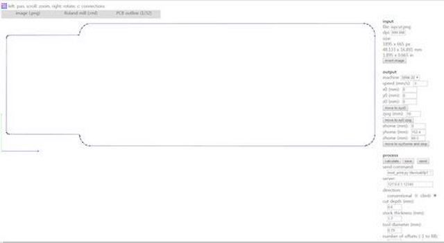
Note: When importing files, check that traces and outline files are the same size
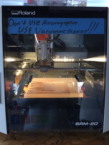
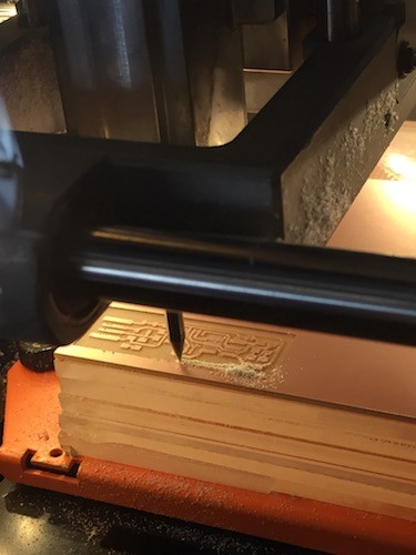
Milling Process
Roland SMR-20
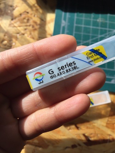
1/64- Tracing Tool
.4 x .8 x 38L = .4 diameter x .8 cut depth x 38 length of tool
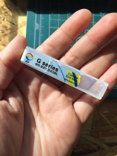
1/32- Outline Tool
.8 x 1.6 x 38L = .8 diameter x 1.6 cut depth x 38 length of tool
For Tracing, use the .4 tool.
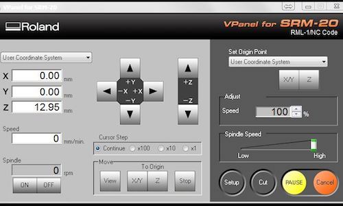
Estimate your X/Y origin (bottom left). Lower the Z so that the tool tip is close to the surface. Use the wrench to loosen the tool to manually and gently lower so the tool tip just touches the copper. Set X/Y/Z origin. Use the machine to increase the Z to about 10-12 (Zjog).
Starting Position for Trace
Ready to Cut- Delete all previous files and find the tracing.rml file and when ready to mill -> Output.
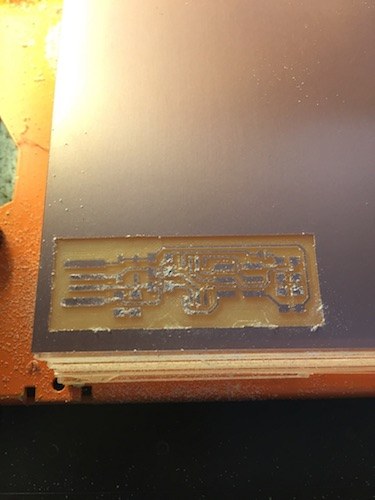
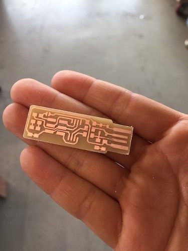
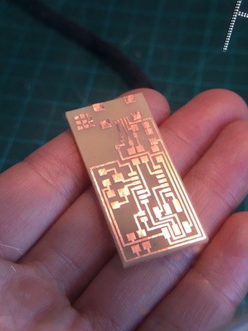
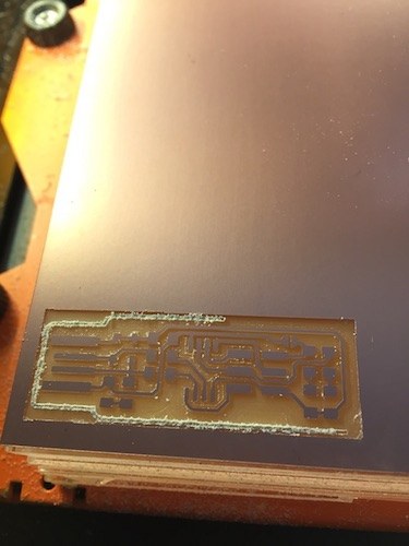
Finished Traces
Replace the milling tool to .8 head when running the outline cut.
Move the milling tool so the tip touches again the surface again and reset Z origin to 0. DO NOT CHANGE THE X/Y origin as it is relative to the tracing file.
Increase Z and GO TO X/Y origin.
Ready to cut- delete previous file and add outline.rml file -> Output
Milling Outlines
Finished Outline
Soldering
Components List
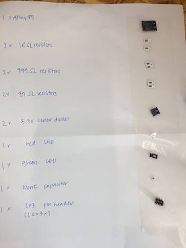
Diodes have positive and negative values so important to check the polarity.
LEDs too- color is on the positive side and negative (line) on the bottom
Resistors & Capicitors do not have polarity so orientation doesn't matter
Resoldering LEDs
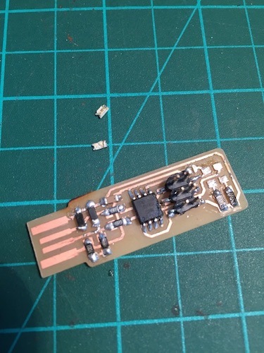
LEDs were attached incorrectly so they had to be desoldered and resoldered.
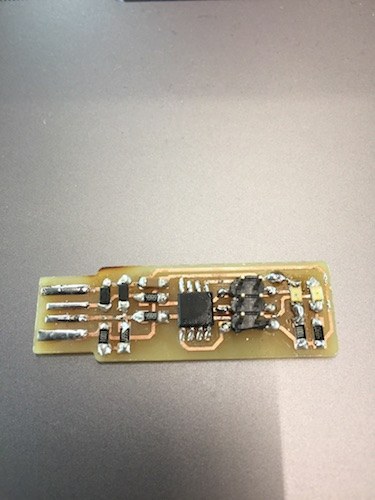
Soldered Board
Check connections with Multimeter
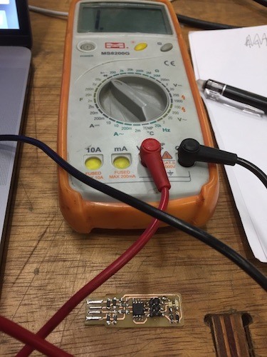
Dial turned to arrow when checking Continuity
Checking resistors- Set dial to next higher scale
All connections seem to be fine and resistors working as they should
Programming
-
Run Make
-
Connecting ISP to Programmer ISP
-
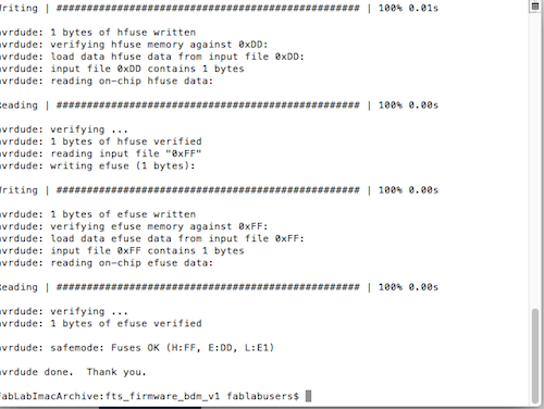
Run Make fuses
-
Check to see if ISP is recognized on device.
-
Run Make rstdisbl
-
Unsolder Jumpers
Making FabOptimus
I was having some trouble with my first board not being recognized by the USB Port on my computer.(See debugging below) I knew I needed a working programmer for future assignments, so I tried another ISP to get more practice and in the case that I wasn't able to program my first one, then I would have a backup. I used Ali's FabOptimus
from the Fab Academy website.
Everything worked on the first try with this board. Yay!
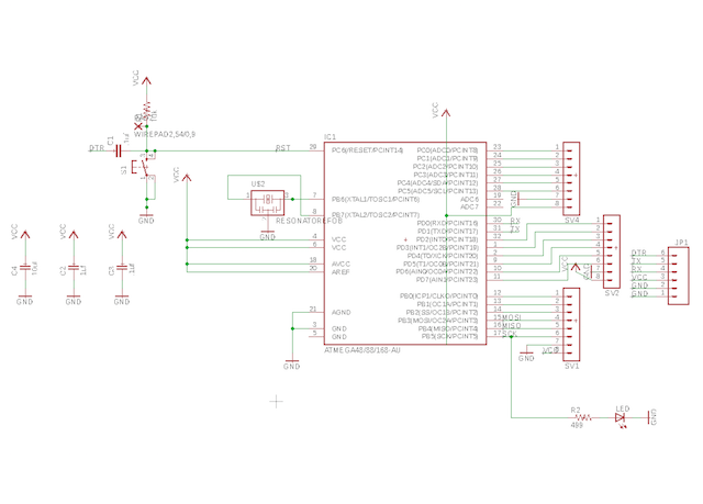
Building FabKit 2.0 Board
FabKit Board & Schematics
Components List
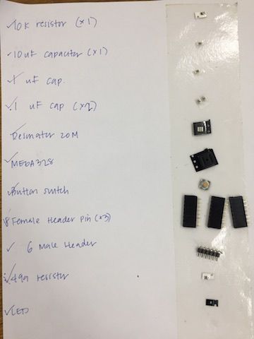
- 10k Resistor
- 10uF Capacitor
- 1uF Capacitor (x2)
- 20MHz Resonator
- ATMega328
- Button Switch
- 8 Header Pin (x3)
- 6 Pin
- 499 Resistor
- LED
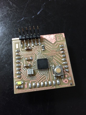
Soldered FabKit Board
TroubleShooting
ATooTiny
<
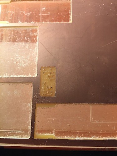
Check the size of object you are milling in the top right corner of fabmodules pages.
Outline Fail
<
Forgot to switch out the milling tool head. Sorry Rodrigo. Luckily, tool head was not broken.
-
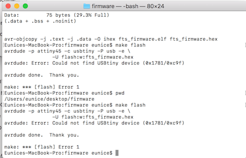
Make flash error message. Cannot read tinyISB
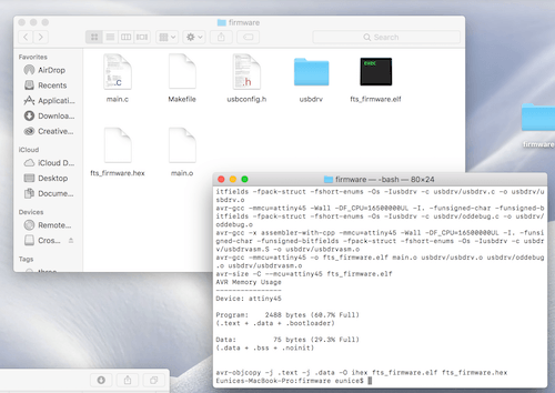
Running Make flash on another computer
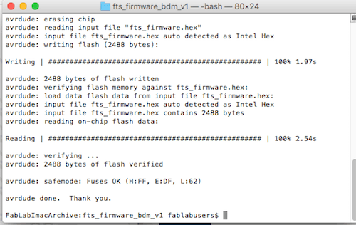
Tried on a different computer. Redownloaded firmware & crosspack. Tried make flash on another mac. It worked. Guessing that because new macs don't have build in USB ports, only firewire/ USB adapters.
-
USB not recognized
When plugging my first FabTiny ISP into the USB port, the computer does not recognize the device.
This one took me a while to figure out. This ISP is connected to the computer by directly plugging into a an USB port(or hub) on the computer. The material however is quite thin so even though I put on extra solder on the ISP's USB pins, it still wasn't reading. I found that the solution to this was to put a thin piece of plastic on the back to give it the thickness to adequate contact with the computer's USB. I took some leftover PLA and put it onto the back of the board and it was able to be read by the computer.
Download Files
Equipment
- Hardware: Roland RM20
- Software: Fabmodules, VPanel, BashTerminal
- Material: Copper PCB board
Fab Modules
I used Brian's FabTinyISP design. Download both trace & outline files.
Creating STL file using FabModules
Go to Fab Modules
Trace Files
Input: Select png and find ISP traces file
Output: Roland mill (.rml)
Process: PCB trace (1/64)
Offset from origin
XO: 0
Y0: 0
Z0: 0
zjog (mm): 10
number of offsets: use minimum 4 or (-1 to fill)
Outline File
reset Fab Modules
Input image(png) -> Outline file
Output -> Roland Mill (.rml)
Process- PCB outline (1/32)
Outline Speed- 0.5 ***
Put offset origin to 0,0,0.
zjog (mm):10
Offset: 1
Machine- SRM 20
RML Outline file
Note: When importing files, check that traces and outline files are the same size
Milling Process
Roland SMR-20
1/64- Tracing Tool
.4 x .8 x 38L = .4 diameter x .8 cut depth x 38 length of tool
1/32- Outline Tool
.8 x 1.6 x 38L = .8 diameter x 1.6 cut depth x 38 length of tool
For Tracing, use the .4 tool.
Estimate your X/Y origin (bottom left). Lower the Z so that the tool tip is close to the surface. Use the wrench to loosen the tool to manually and gently lower so the tool tip just touches the copper. Set X/Y/Z origin. Use the machine to increase the Z to about 10-12 (Zjog).
Starting Position for Trace
Ready to Cut- Delete all previous files and find the tracing.rml file and when ready to mill -> Output.
Finished Traces
Replace the milling tool to .8 head when running the outline cut.
Move the milling tool so the tip touches again the surface again and reset Z origin to 0. DO NOT CHANGE THE X/Y origin as it is relative to the tracing file.
Increase Z and GO TO X/Y origin.
Ready to cut- delete previous file and add outline.rml file -> Output
Milling Outlines
Finished Outline
Soldering
Components List
Diodes have positive and negative values so important to check the polarity.
LEDs too- color is on the positive side and negative (line) on the bottom
Resistors & Capicitors do not have polarity so orientation doesn't matter
Resoldering LEDs
LEDs were attached incorrectly so they had to be desoldered and resoldered.
Soldered Board
Check connections with Multimeter
Dial turned to arrow when checking Continuity
Checking resistors- Set dial to next higher scale
All connections seem to be fine and resistors working as they should
Programming
-
Run Make
-
Connecting ISP to Programmer ISP
-
Run Make fuses
-
Check to see if ISP is recognized on device.
-
Run Make rstdisbl
-
Unsolder Jumpers
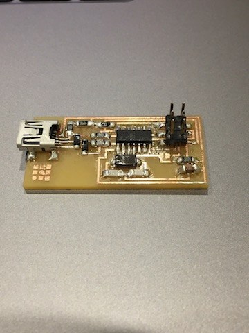
Making FabOptimus
I was having some trouble with my first board not being recognized by the USB Port on my computer.(See debugging below) I knew I needed a working programmer for future assignments, so I tried another ISP to get more practice and in the case that I wasn't able to program my first one, then I would have a backup. I used Ali's FabOptimus
from the Fab Academy website.
Everything worked on the first try with this board. Yay!
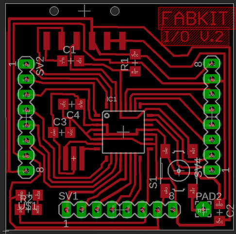
Building FabKit 2.0 Board
FabKit Board & Schematics
Components List
- 10k Resistor
- 10uF Capacitor
- 1uF Capacitor (x2)
- 20MHz Resonator
- ATMega328
- Button Switch
- 8 Header Pin (x3)
- 6 Pin
- 499 Resistor
- LED
Soldered FabKit Board
TroubleShooting
ATooTiny
<
Check the size of object you are milling in the top right corner of fabmodules pages.
Outline Fail
<
Forgot to switch out the milling tool head. Sorry Rodrigo. Luckily, tool head was not broken.
-
Make flash error message. Cannot read tinyISB
Running Make flash on another computer
Tried on a different computer. Redownloaded firmware & crosspack. Tried make flash on another mac. It worked. Guessing that because new macs don't have build in USB ports, only firewire/ USB adapters.
-
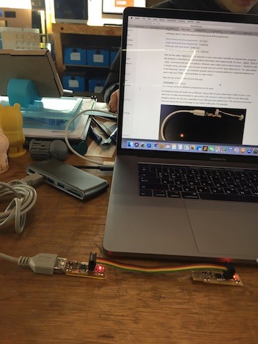
USB not recognized
When plugging my first FabTiny ISP into the USB port, the computer does not recognize the device.
This one took me a while to figure out. This ISP is connected to the computer by directly plugging into a an USB port(or hub) on the computer. The material however is quite thin so even though I put on extra solder on the ISP's USB pins, it still wasn't reading. I found that the solution to this was to put a thin piece of plastic on the back to give it the thickness to adequate contact with the computer's USB. I took some leftover PLA and put it onto the back of the board and it was able to be read by the computer.
Download Files
Run Make
Connecting ISP to Programmer ISP
Run Make fuses
Check to see if ISP is recognized on device.
Run Make rstdisbl
Unsolder Jumpers
ATooTiny
<Check the size of object you are milling in the top right corner of fabmodules pages.
Outline Fail
< Forgot to switch out the milling tool head. Sorry Rodrigo. Luckily, tool head was not broken.
Make flash error message. Cannot read tinyISB
Running Make flash on another computer
Tried on a different computer. Redownloaded firmware & crosspack. Tried make flash on another mac. It worked. Guessing that because new macs don't have build in USB ports, only firewire/ USB adapters.
USB not recognized
When plugging my first FabTiny ISP into the USB port, the computer does not recognize the device.This one took me a while to figure out. This ISP is connected to the computer by directly plugging into a an USB port(or hub) on the computer. The material however is quite thin so even though I put on extra solder on the ISP's USB pins, it still wasn't reading. I found that the solution to this was to put a thin piece of plastic on the back to give it the thickness to adequate contact with the computer's USB. I took some leftover PLA and put it onto the back of the board and it was able to be read by the computer.