| Seonghee Kim | |
| 4. Computer Controlled Cutting | |
| HOME | ABOUT | ASSIGNMENTS | FINAL PROJECT | CONTACT | |
Week4
Assignment
-group assignment
characterize your lasercutter, making test part(s) that vary cutting settings and dimensions
-individual assignment
cut something on the vinylcutter design, lasercut, and document a parametric press-fit construction kit, accounting for the lasercutter kerf, which can be assembled in multiple ways
Hardware and Softwares used
-Fusion 360
-Graphtec Studio
-GoldenLaser Cut & Scan control
-Makercase
-Graphtec cutting pro
-K2 laser JG10060
Outcome
Vynle cutting was first time to me. The pressure value is ciritical to make good result. And for laser cutting with good presfit was challenging. So I have to know about the kerf. I made lots of mistakes to make correct presfit. Parametic design was really helpful to find right kerf value. For the vynle cutting, I used svg file I made last week with Inkscape.
Vinylcutter
Graphtec Studio
I only had to know sevral menus to cut the vinly sheet. It has very simple interface. But to find a right value, I had to try many times.
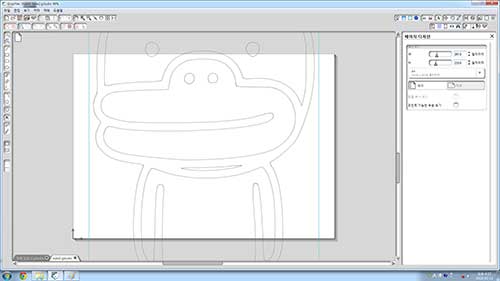 -open svg file, you can see size is too big.
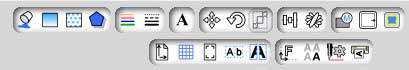 -see tools at upper right
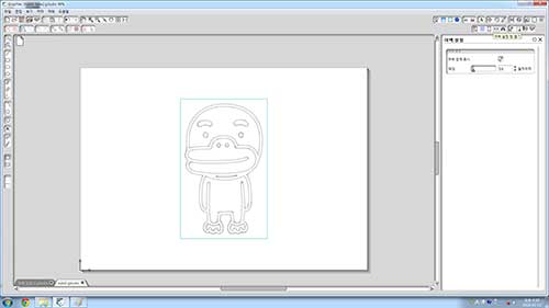
 -click size button and change to appropriate size.

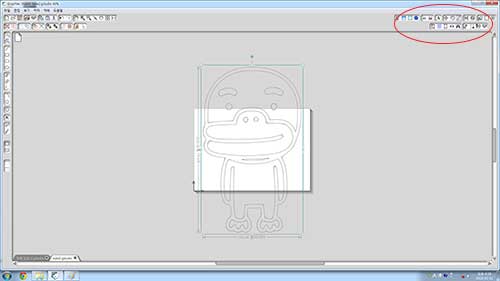
-this tool makes you the border line and cut.

-send Gcode to machine.

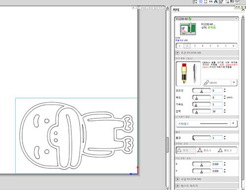
-I choosed 16 for pressure value.
Graphtec cutting pro
To hold the vinyl sheet, I had to use vacuum, but becusee of the maintenace, the pressure was week, so I stick the masking tape to hold firmly.
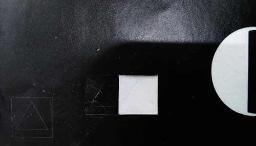 -test first. Coners of the squre is not accurate. It is because pressure value is too big.
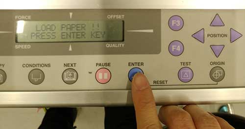 -using the arrow keys, get the start position and press the origin button. Origin button makes beep sound.
-press enter.
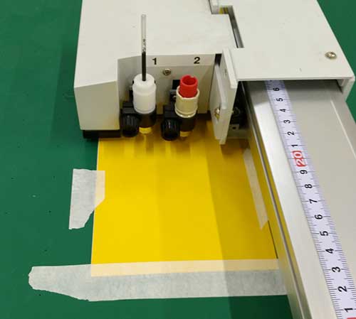 -It has two types of tools, no1 is just pen and no2 is the knife for cutting.
 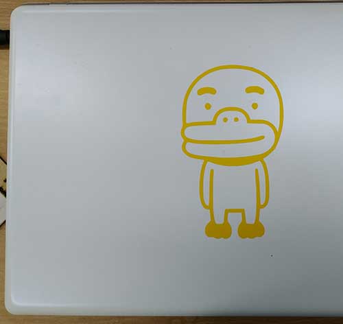 -Remove left over. I used fingernail but I recommand to use special sheet to remove it.
 -click here to download the svg file
Laser Cutter
GoldenLaser Cut & Scan control
GoldenLaser control software has simple interface. Easy to understand. But same to vinyl cutter, to find a right value, I had to try many times.
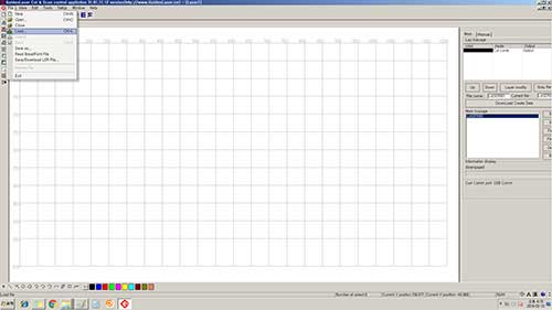 -load dxf file.
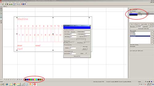 -Select the layer color, and put the valuse.
-Power 85, speed 15 for cutting.
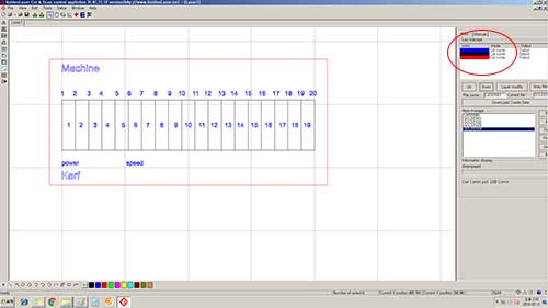
-power 65, speed 65 for lineing. but it showed cutted.
K2 laser JG10060
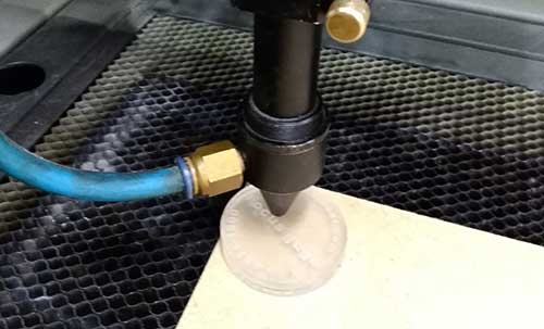 -check z value first.
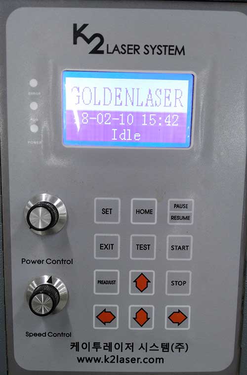 -Using arror button, get the x,y vulue. K2 laser does not have origin button. Once you set the place of laser, there would be the origin automatically. Press start.
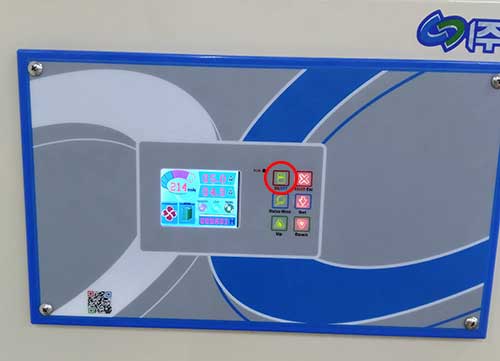 -Next to K2 laser cutter, there is a dust collector seperatly so power on before working the Lasercutter.
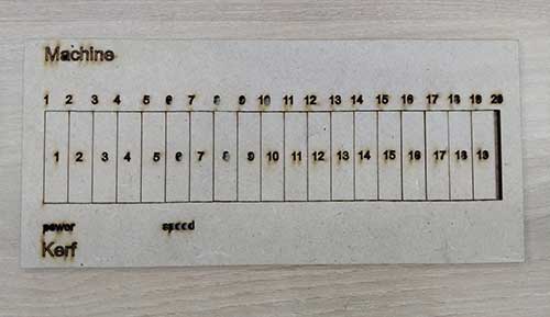
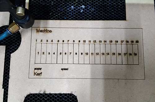 -I made this to measure the kerf later.
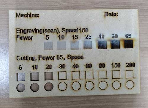 -I tried engravings, cutting, and lining. For the text I used power85, speed65, but it showed cutted. Diffrent from the squre and circle on the measurmant. I made the text from fusion 360, maybe that contains more lines than it showed.
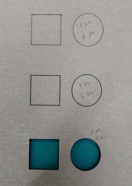 -This is a value test for cardboard.
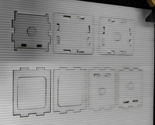 -I also tested PP with the automata box which I designed for week3 assignment.
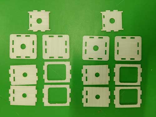 -I printed it different way, one is vertical, another horizontal.
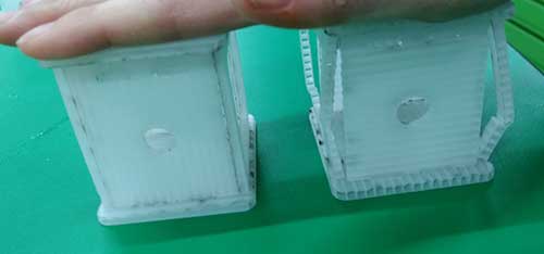 -Printing horizontal looks stronger.
Find Kerf
Kerf is defined as the width of material that is removed by a cutting process.I tried to find the kerf matching K2 machine and some materials.
 -I made 20 cutting lines. After cutting I pushed all to left to check the removed width.
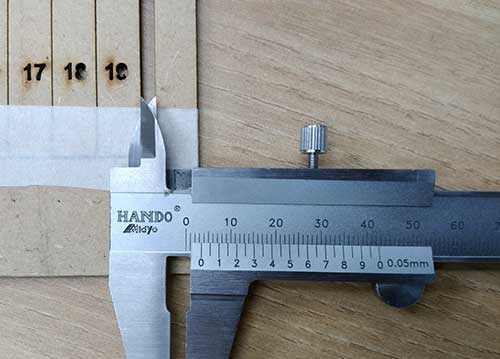 -Callipers showes 3.25mm. Divide 3.25 with 20. The number 0.16125 is approximate kerf value.
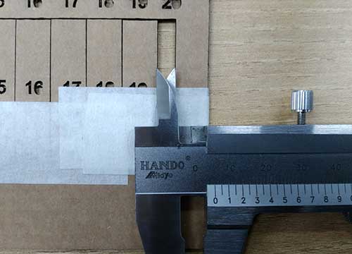 -This image shows checking the kerf for cardboard. 5.10/20=2.10, so 2.10 is an approximate kerf value.
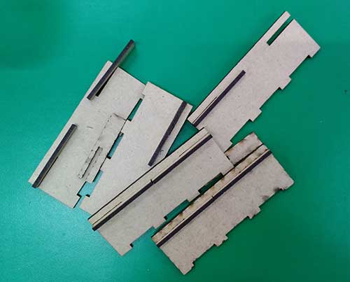 -Still the value I checked was not exact one, I had to make couple of mistakes.
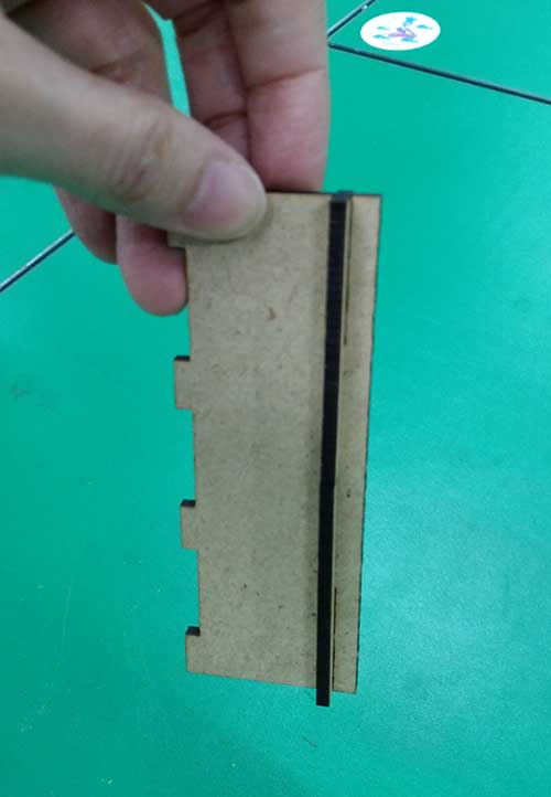 -Finally, I found the right one.
Parametric Design
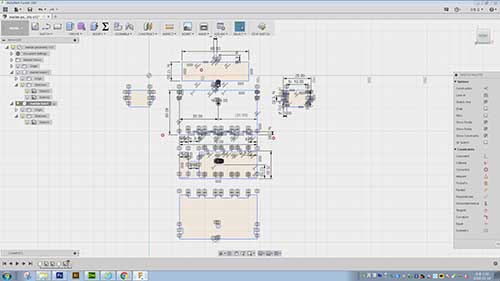
Fusion 360
Parametric design is based on algorithm. I tried to make an small marble machine kit which allows to organize the marble road. Comparing the marble box which is non parametirc design(I showed end of this document), Parametric design was really useful to make change the thickness of material and matching kerf value.
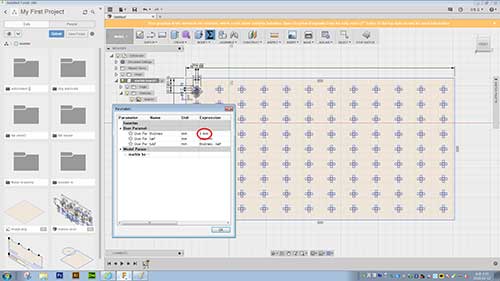
 -This two images are for thickness value 3 mm.Upper image is the basic marble machine board. The second image is for the shelf which is used for marble road. Thise are designs for my final project.
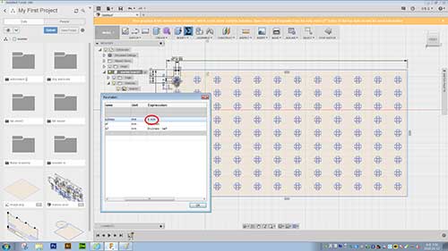
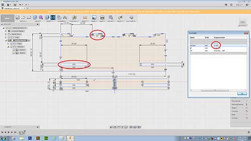
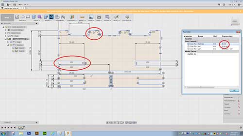 -This design is for thickness value 5 mm. Clear changes can be seen.
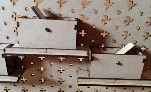
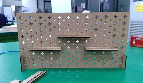 -I make the basic board for marble tracer! It is firm enough and possible to changes the shelf!
-K2 laser: power 85, limited power 80, speed 15
-MDF 3mm thick, kerf 0.17
Maker case
Maker case is the website software which allows to make box easily. It programed argorithm based. Simply put the numbers for height, width, and depth of the box. Then I can get the lasercutter plans calculate with value. But unfortunatly it was now work well.
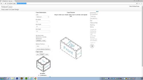 -put the height, width, depth of the box, choose edge joint and generate it.
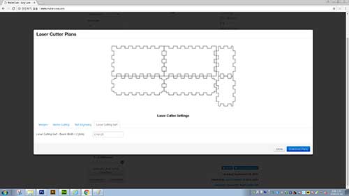 -put kerf value and download svg file.but when I import the svg file from fusion360, the size of box is much smaller then I put the values on the web.
-I also tried to convert from illustrator dxf file and to fusion360. That time the size goes exactly but still kerf was not good. It does not look like changed even I changed the value at website. so I deciede to sketch my own.
 -I did the quick design which is not parametric due to lack of time.
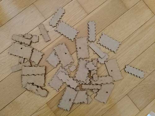 -As you see, I made to many fails and still not possible to get right one.
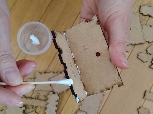 -The boxes are not firm at all so I had to use glue to fix it. Now I clearly know advantages of parametiric design.
 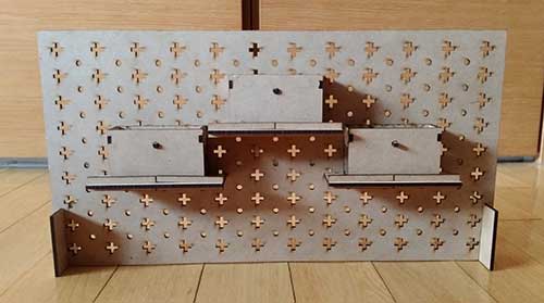 -Here goes small test version for marble machien
-click here to see movie how it works
 -It has problem which the board in the box did not come back horizontaly after rolling marble once. The board has to be parallel horizontal after the marbles goes through. I have to fiqure it out for the final project.
 -click here to see movie how it works
downloads
-click here to download the f3d filereferences
-Kerf
http://www.esabna.com/us/en/education/blog/what-is-cutting-kerf.cfm
Date: 2018-02-013 Author: Seong Hee Kim @ Fablab Seoul