| Seonghee Kim | |
| 7. Electronics Design | |
| HOME | ABOUT | ASSIGNMENTS | FINAL PROJECT |CONTACT | |
Week7
AssignmentS
-group assignment
use the test equipment(digital voltmeter, oscilloscope, regulated power supply) in the lab to observe the operation of a microcontroller circuit board-individual assignment
redraw the echo hello-world board, add(at least) a button and LED(with current-limiting resistor) check the design rules, make it, and test it.optially simulate its operation and render it.
Hardware and Softwares used
-Eagle
-Fab modules
-Roland's SRM-20
-digital voltmeter, oscilloscope, regulated power supply
Outcome
Since it is first time to use Eagle software, I had to follow the tutorial step by step.
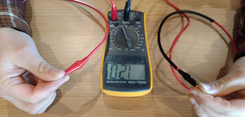
Digital voltmeter
We did a connectvity test with digital voltmeter.
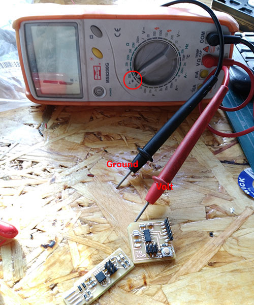
Body resister is 1.20ohm.
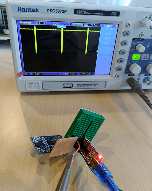
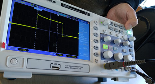
Oscilloscope
Oscilloscope is another useful tool for debuging. It can check frequency, noise, and amplitude over time. However it looks a bit complicated.
click here for sparkfun oscilloscope tutorial
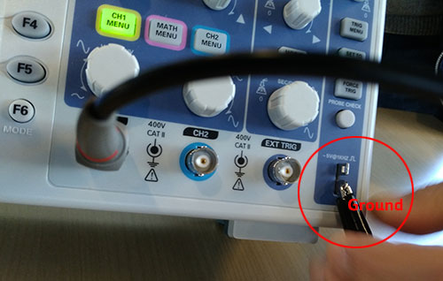
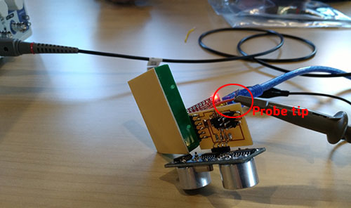 Put probe tip on circuit board. we are using breadboard and external wire to protect the board.
Eagle
Eagle is a software to help designing pcb layout, schematic and board drawing. It has a lot of component labiries so easy to draw exact pcb layouts. Fab Academy also has a component library, fab.lbr.
Rodigo, our instructor recommanded to use eagle since I never used other pcb editing program(and even not familiar of PCB itself). Eagle is easy and generally to be used, so there are many references. Also it's design is able to import to fusion 360, so later I can use for detailed design process.
-download eagle
-download fab.lbr, select files and click clone and download button.
-click here to see how to use eagel on fusion 360
Schmetic Drawing
Schmetic is a circuit drawing. Using symbols of elctronic components, I can draw an any circuits.Basic commands for schmetic are
- - add = opens up the libraries so that you can add components in Schematic view
- move = moves an item
- net = makes a logical connection
- junction = adds a junction- value = addes value to components (i.e. ohm rating)
- name = names a component
- label = displays the name of a component in schematic view
- copy = copies an existing component on the schematic.
- ERC = electronic rules check; this ensures your board will actually work (use in schematic view)
-
-
-
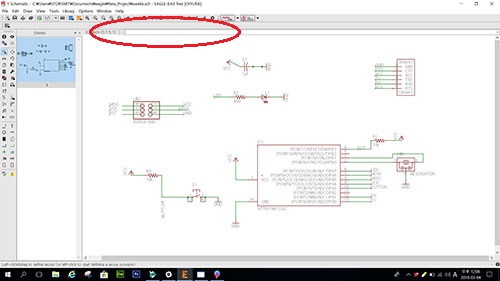 -write down the commands in command line. I don't understand what those are exactly mean, specailly MOSI, MISO, SKC etc. I just try to follow the tutorial as same as possible. Size of componets, appearance, place of symbols.
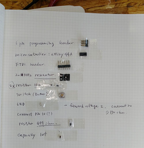
-add components; 6 pin header, attiny44, FTDI header, resonator 20MHz, 2*Resistor 10k, switch(buton),LED, registor 499.
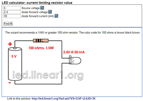 -For LED registor, see the LED1206 datasheet and using LED calculaotr , get the proper value.
 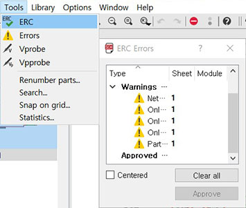 -When you finish drawing, Tool>ERC. And fix everything.
 Board layout
To make PCB, I have more steps. I need to change board view, and route trace. It looked easy but was somewhat complicated. I did it autoroute first time, than it did not work right, so I had to do it all over again from schematic.
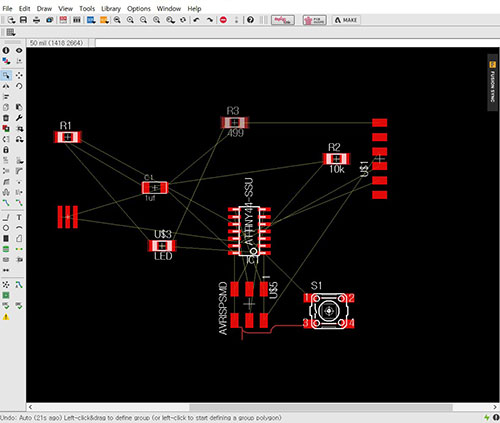
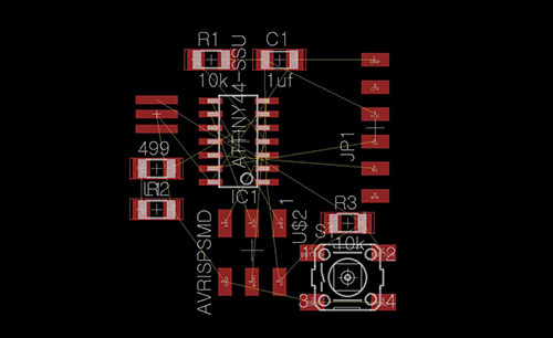
-Change to board view. and arrange the componets where I want to be.
-Fail! First, I did autoroute because I thought after autorouting I can change easyer, but it didn't work like what I think. so I had to go schematic, save it as diffrent name and make new board view.
 -re open the board view, arrange components again.
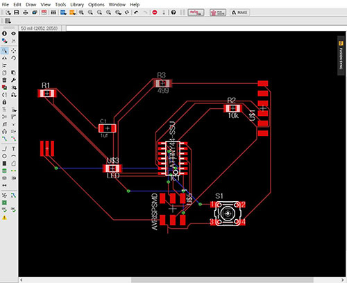
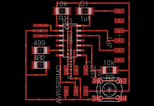 -Route it manually. 16 width line. it looks neat and good!!
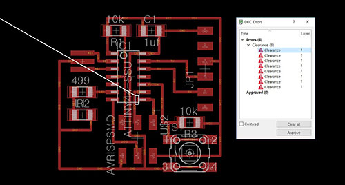
-Download the DRC check, fabmodule.dru. and check DRC.
-Eventhough it looked good, when I check the DRC, I have 8 errors. It shows with red line. So I change the width of routher and grid try to fix it.
-Finished!
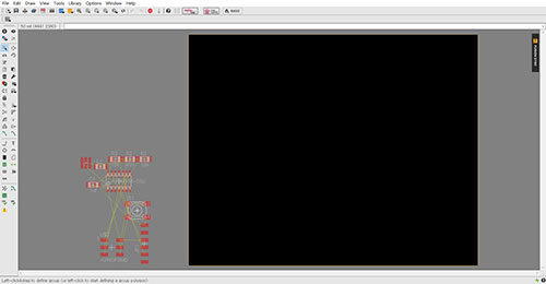
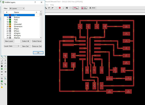 -Select only 1 top layer. and export it.
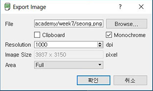
-check monochrome, 1000dpi.
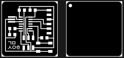
-download files from here. trace.png, outline.png
--download files from here. schemetic, board file
CNC milling
This is what I learnt from week 5.
fab modules
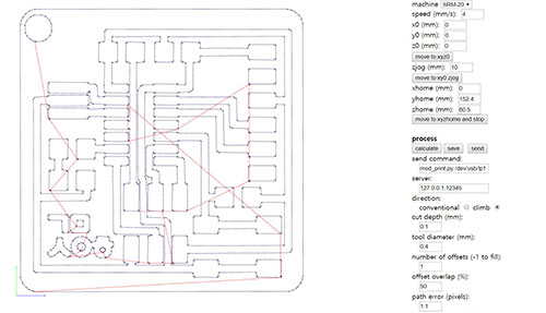 -I selected number of offsets '1' and checked again if the lines are too close. Every things look fine. After check it I changed number of offset '-1' and milling it.
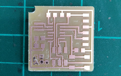 -A hole is teared off. Too close from the outline. I didn't check the diagram of nmill.
Soldering.
 -Find components. For the FTDI header, I had to bend the underneath parts about 90 degree.
 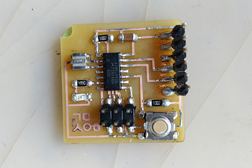 -Done! I can see my second soldering is imporved!!
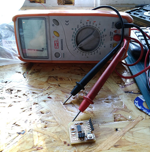 -I tested the connection. Everythings ok!
Programming ISP
-To program helloecho pcb, I had to program my FabISP first. Because I failed it at week5, I had to step back from zidig. But it failed again and again. so I tried on Mac at our lab. FabISP is programmed!!
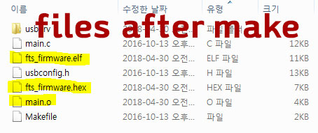
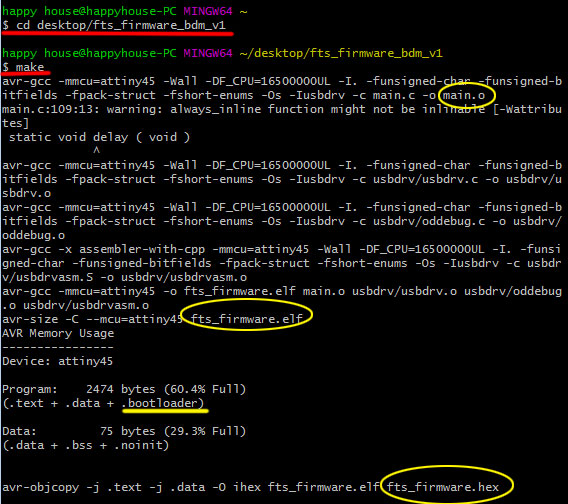 -type 'make' to make .hex .elf .o files
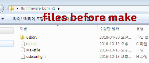
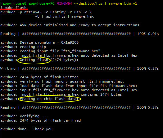 -type 'make flash' to embed program on flash memory.
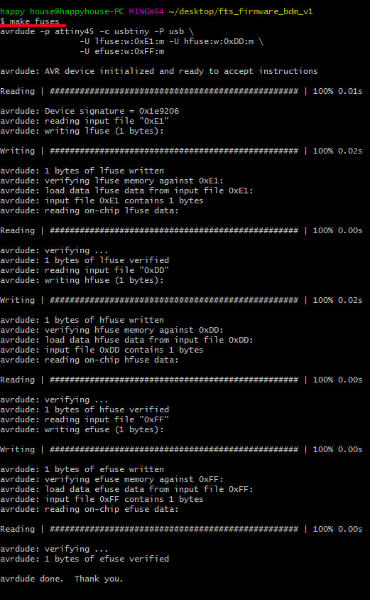 -type 'make fuses' to configuration.
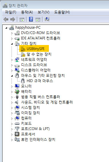 -I checked my USBtinySPI connectec well before disable the reset. Because after the next step 'make rstdisb' the board can not program again.
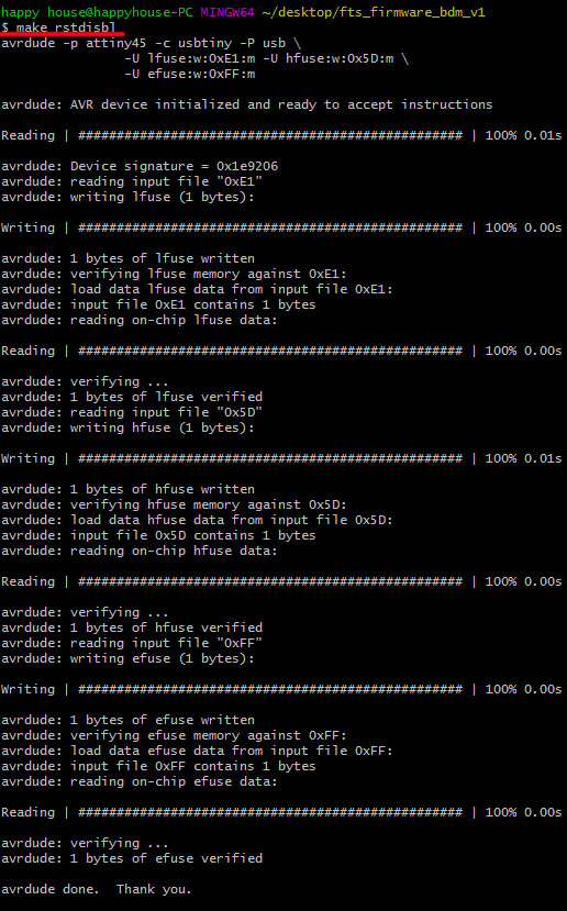 -type 'make rstdisbl', it redo the fuses then disable the reset. After this command I can not reprogram this board.
Button turns on the LED
-I succeded the board running on week9 assignment for embaded programming. To see how it works click week9.
KiCad
KiCad is free to use. Eagle is also free but a limited restriction. Now I am a beginner, so it's good enough to be a free version of Eagle, but I want to study more about Kicad for the future use. It is because I found out Kicad is easy to modify the board design, and its short key makes faster to work. However Kicad has steps to be added compared to Eagle. Such as annotating or creating a netlist need. And while Eagle provides a fab library, Kicad had difficulty find and select each components.-click here to see how to draw from KiCad(Korean version)
-click here to download KiCad.
Schmetic Drawing
 1. new project
2. select .sch file
3. 'H' keypad to go fit size view
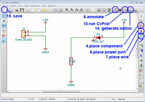
4. place component
5. 'Y' keypad to mirror y axis
6 ,place power port
7. place wire 8. annotate schematic components
9. right mouse click and select fied to edit value
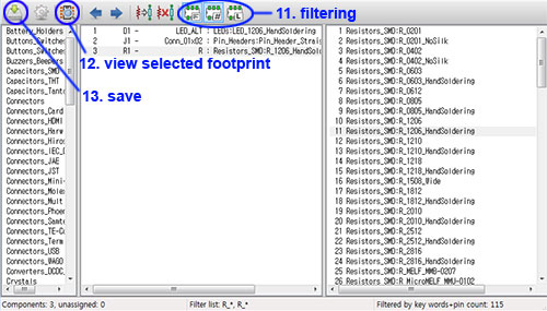
10. run CvPcb to associate components and footprints
11. filtering(keyword, pinnumber, labrary)
12. view selected footprint
13. save 14. geberate netlist
15. save sch
-When you finish drawing, Tool>ERC. And fix everything.
Board layout
16. open _pcb file
17.'H'keypad to go fit size view
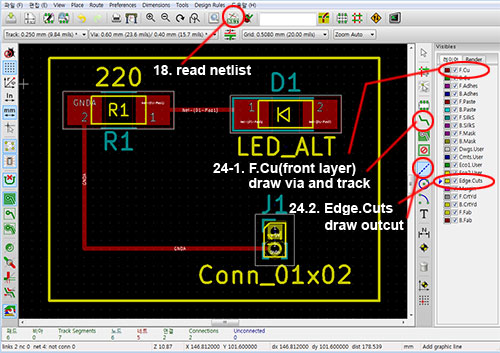
18. read netlist
19. read current netlist
20. close
21. right mouse click to move or
22. 'M' move
23. 'R' rotate 24. select layer
24-1. F.Cu(front layer) --> draw via and track
24.2. Edge.Cuts --> draw outcut with grapic line
-download files from here(click test.pro file to open)
Date: 2018-03-05 Author: Seong Hee Kim @ Fablab Seoul