WEEK 12 - OUTPUT DEVICES
Assignment
individual assignment :
add an output device to a microcontroller board you've designed,
and program it to do something
group assignment :
measure the power consumption of an output device
Here is the link to Group assignment.
MOTORS
http://www.pbclinear.com/Download/DataSheet/Stepper-Motor-Support-Document.pdf
https://casunmotor.en.alibaba.com/product/60372825334-221076608/42SHD0024_20A_mini_stepper_motor_nema_17_42x34mm_3D_printing_cnc_router.html
BOARD DESIGN
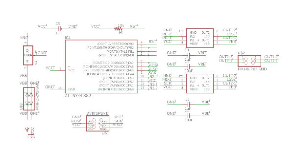
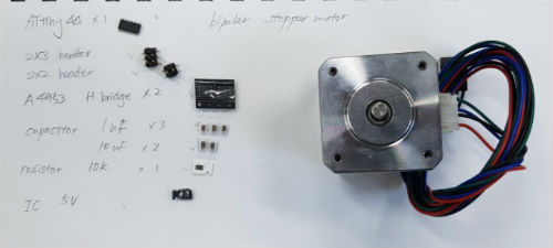
I used the board that is on class page. Different to board I made before, board for stepper motor needs higher voltage. So I should put another power and make route thicker. But, micro controller still use voltage under 5v so regulator should be included to lower the voltage. And to divided those two voltage, there is component called h-bridge. And, bipolar stepper motor need 2 h-bridges.
I designed board with Autodesk eagle. I loaded every components like capacitors, resistors, h-bridges, MCU and headers on schematic. And I connected every component by label.
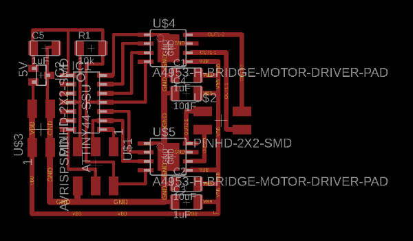
then I opened board file and place components and make routes. Routes for 5V are 16mil and routes for over 5V are 24mil. When I export board to png file, I made size bigger regardless to resolution. So I measured length of ATtiny 44’s pin and modified png file on Photoshop. It was 8.1mm. Then I created outline file.
MILLING AND SOLDERING
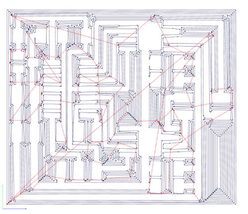
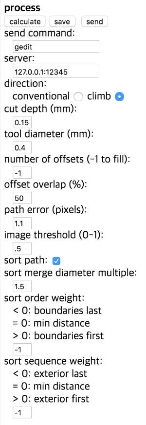
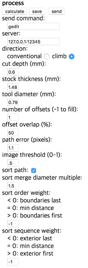
I loaded those file on Fabmodules, but there are two parts that paths were not calculated. So I made those pixels larger.

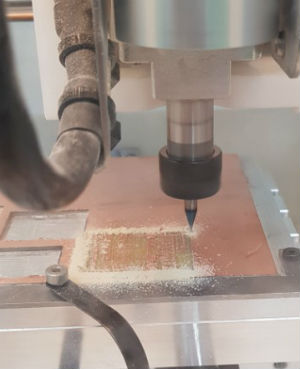
Milling
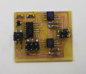
milling was fine.
Soldering
I arranged all the components I need on paper and soldered. Soldering was fine too.
PROGRAMMING
I connected the board to ISPboard but the leds weren’t light up.
Before works were with FTDI cable to provide power. So I think I should give a power to board to program it. I connected the board to power supply and slowly raised the voltage. When voltage was about 2V LEDs lit up, I tried to programming using C.

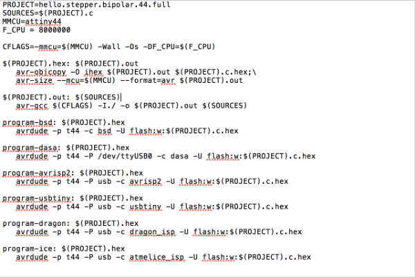
But there was error message saying ‘missing separator’. I searched for this and found the reason. It was about separator that regulates command in makefile. 3 space or tab were used for that. But there was problem so I changed every space to tab on text editor and saved.
this is the error message.

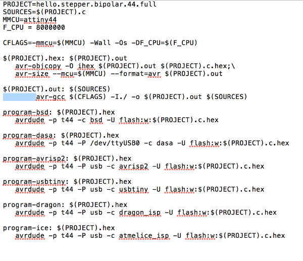
I changed these spaces to
this tabs
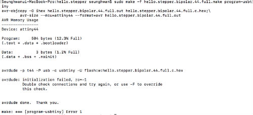
I tried makefile again. But there was second error message saying ‘target pattern contains no %’. I couldn’t understand what was wrong.

I just downloaded c file again and modified to tab again. And I tried again and It programmed well. I removed ISP and connected motor. But I wasn’t sure which pin will be connected to which pin. I looked for data sheet and find pin numbers.
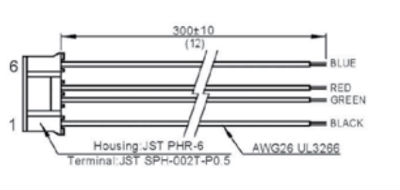
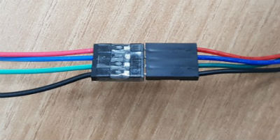
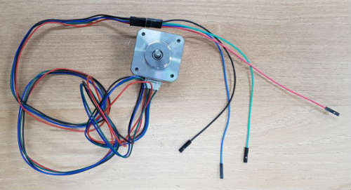
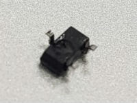
The motor I used was Nema 17 bipolar stepper motor and it has 4 pins. Here is the image of its pins. I thought each h-bridge goes to one pin and opposite pin of it. I named h-bridge on the top 1 and 2 on the bottom. And I raise voltage up to 5V and motor started to vibrate not rotated. And first I raise the voltage ampere went up together, but from a moment ampere stayed at 0. Then motor stopped vibrating. I thought something wrong with the board. At that moment tiny smokes rose up.
and i tried to program again and computer didn't read the board.
After regional review I noticed regulator got burn maybe. I desoldered regulator and there was burn mark at the bottom.
I resoldered new 5V regulator. And programmed again.
and I also realized there was mark that told pin number on Neil’s board. I followed that number and connected to motor. Then motor rotated well. I raised voltage until 9V.
I also tried with the 9V battery. I worked well.
PROGRAMMING with ARDUINO IDE
I also tried with arduino IDE and code.
Here's the code.
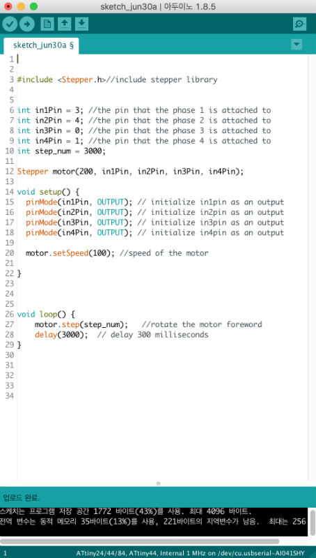
I made it turned 3000 steps. 1 step is 1.8degree for usual NEMA 17 stepper moter. So it should rotate 540degree. But mine was different so 3000 steps were more than that. and also after rotating one loop, It stopped for 3 seconds and rotating again using delay command.
Here's the video.
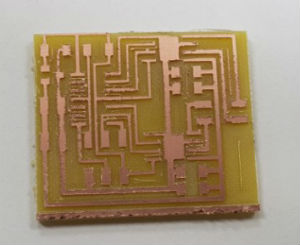
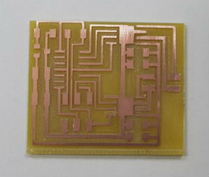
Here are my works.
Download