WEEK 16 - MACHINE DESIGN
Assignment
group assignment :
- actuate and automate your machine
- document the group project and your individual contribution
Here is the link to Group assignment.
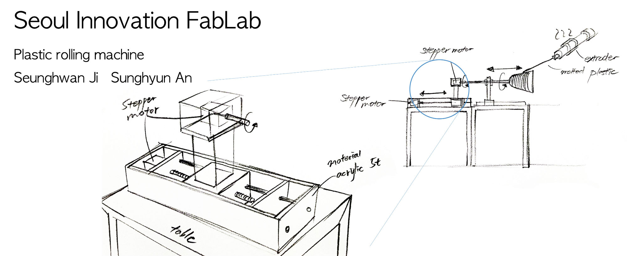
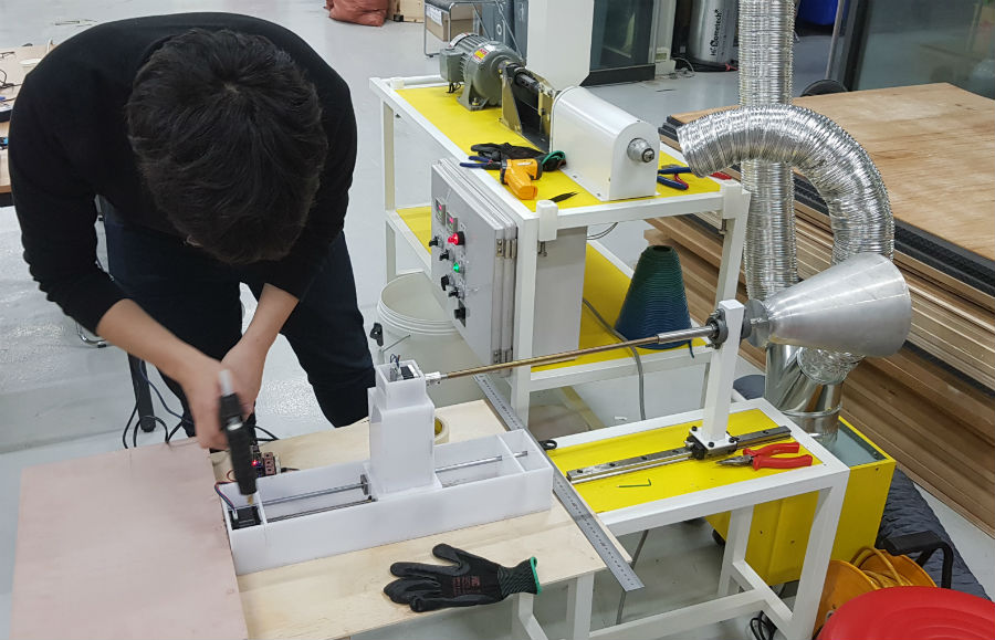
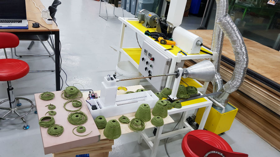
machine making
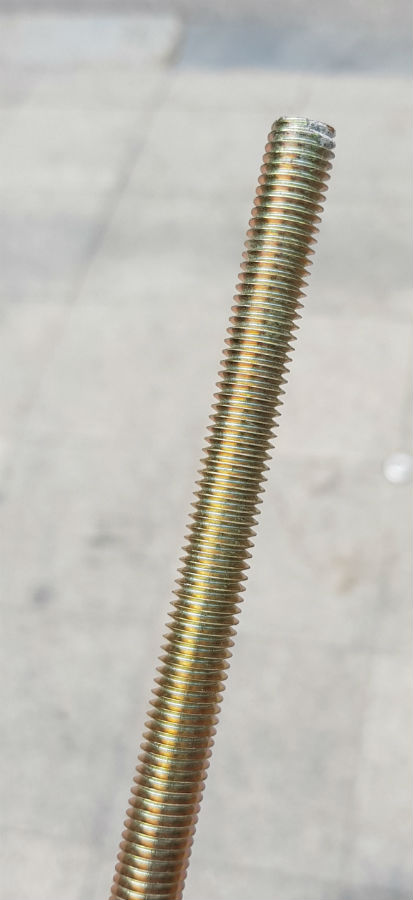
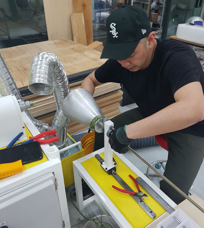
To connect motor and shank, I machined m10 bolt with lathe. Coupling was 8pi, so I cut 1mm to make 8pi. It was okay.
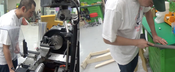
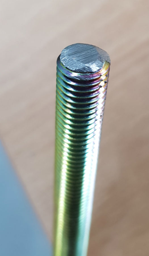
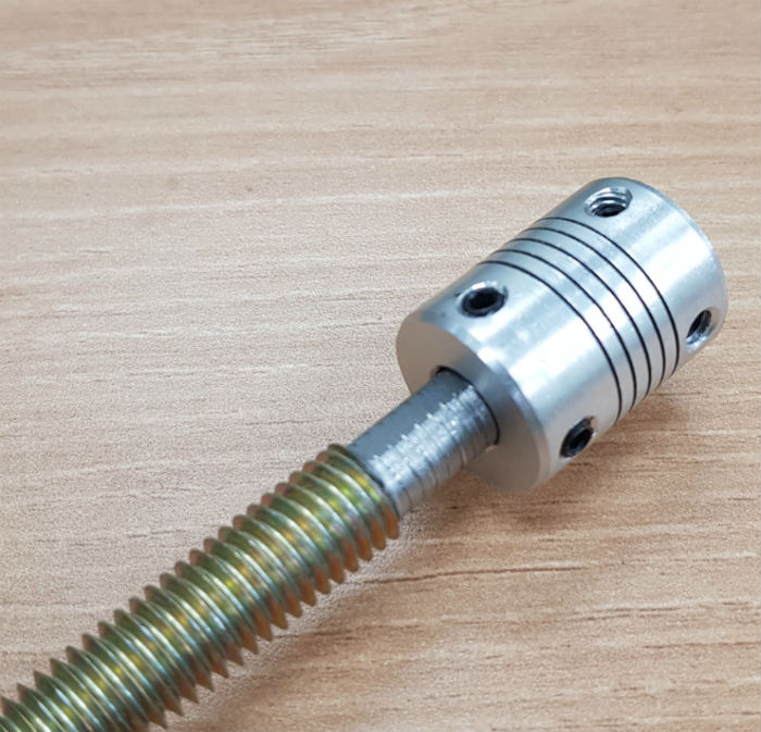
Then filed one side to make flat surface to fasten with the bolt.
It was okay.
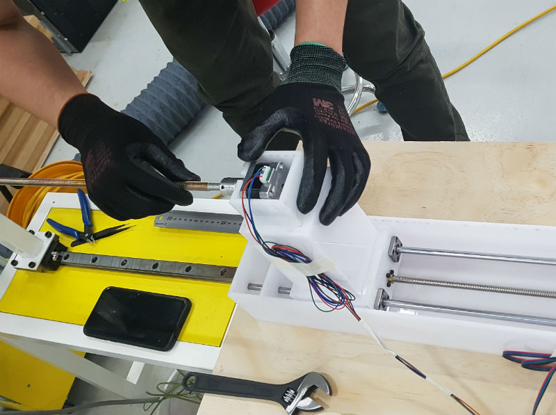
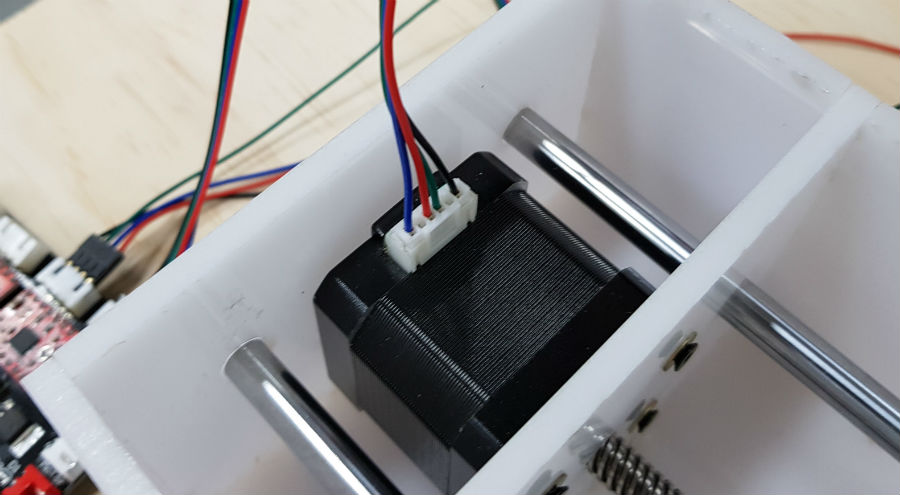
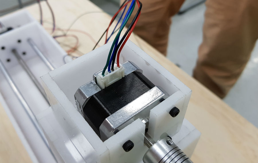
Aligning machine and linear guide.
GRBL
We studied grbl first which is most common software to run machines that use motor and G-code. Grbl is a free, open source, high performance software for controlling the motion of machines that move, that make things, or that make things move, and will run on a straight Arduino. A lot of makers and companies are using this program to run machines.
Here's link of GRBL's github.
Here are the G-code to run machines.
G38.3, G38.4, G38.5: Probing
G40: Cutter Radius Compensation Modes
G61: Path Control Modes
G91.1: Arc IJK Distance Modes
Supported G-Codes in v0.9h
G38.2: Probing
G43.1, G49: Dynamic Tool Length Offsets
Supported G-Codes in v0.8 (and v0.9)
G0, G1: Linear Motions
G2, G3: Arc and Helical Motions
G4: Dwell
G10 L2, G10 L20: Set Work Coordinate Offsets
G17, G18, G19: Plane Selection
G20, G21: Units
G28, G30: Go to Pre-Defined Position
G28.1, G30.1: Set Pre-Defined Position
G53: Move in Absolute Coordinates
G54, G55, G56, G57, G58, G59: Work Coordinate Systems
G80: Motion Mode Cancel
G90, G91: Distance Modes
G92: Coordinate Offset
G92.1: Clear Coordinate System Offsets
G93, G94: Feedrate Modes
M0, M2, M30: Program Pause and End
M3, M4, M5: Spindle Control
M8, M9: Coolant Control
UNIVERSAL G-CODE SENDER
We should check motors were fine. We used Universal G-code sender because we don’t need complicated code we needed to control motor speed only.
You can download program at github here.
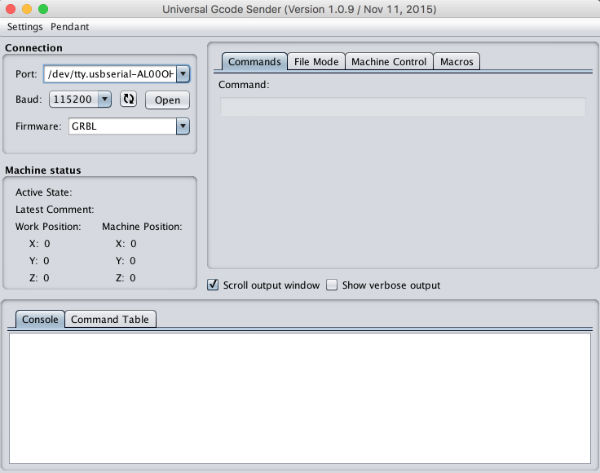
It can send code to motor driver directly.
Connecting computer, motor driver and motors.
I put cable to motors and motor driver there were 4 pins each. I was not sure of connecting right pins. Then, connecting computer and motor driver with 5pin cable. If you connect computer and motor driver, you could see the port on the g-code sender window. and to activate motors you need 12V power separately. We used 12V 5A power adapter.
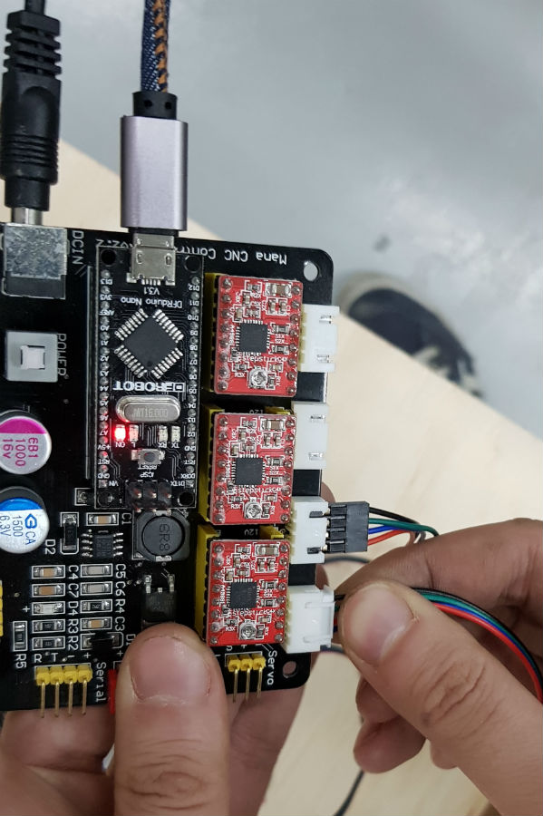 This is motor driver we use. We used only X, Y axis.
Then I opened the port on program and put location X first and it was rotating. It means pin connection was right.
And when I tried to turn Y motor, it vibrated. So I fixed it and motor rotated well. And you should check if there were any heat on the motor. If it was not, it means connection is fine.
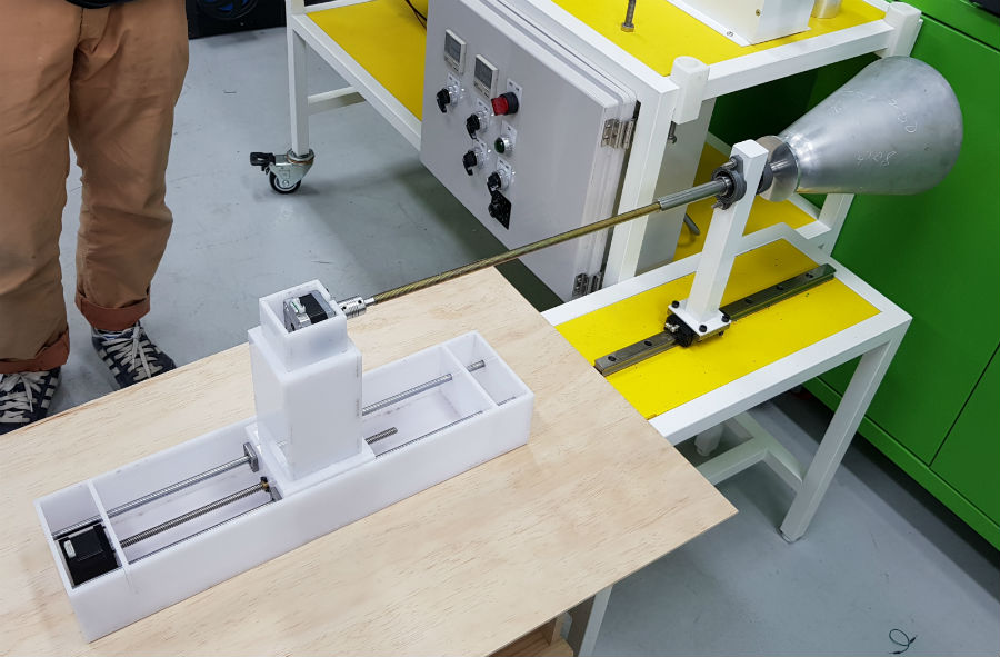
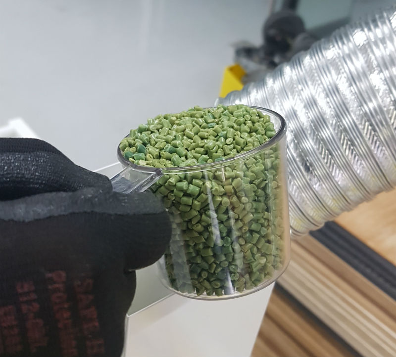
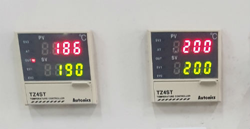
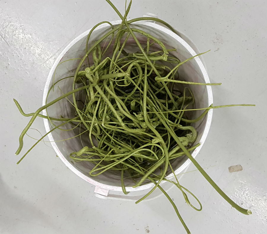
EXTRUSION TEST
We used green recycled plastic pellet. It's PP. And radiator's temperature is 190 and 200 each.
For rolling the plastic string both X and Y motor speed should be fixed. When Y motor that is upper part rotating shaft and aluminum template turns once, X axis should move about 4mm that is thickness of plastic string.
But template has corn shape that has round tip. It was too difficult to control speed on each part because the diameter of layer gets larger. So we decided to control extruding speed.
So on the program we modified $100, $101, $110, $111, $120, $121, $130, $131 setting.
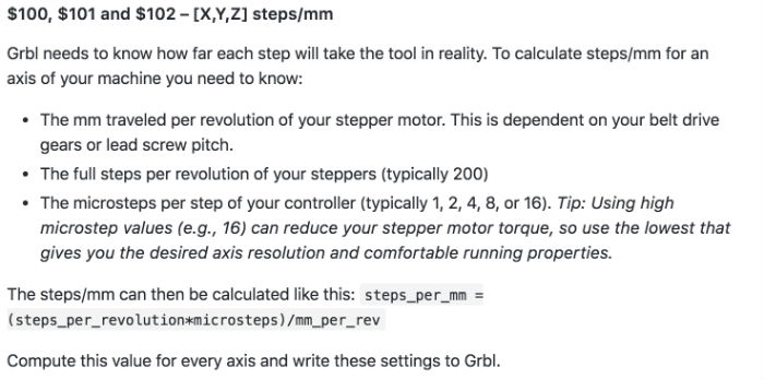
$100 and $101 are step/mm of X, Y
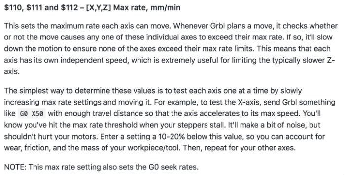
$110 and $111 are max rate of X, Y
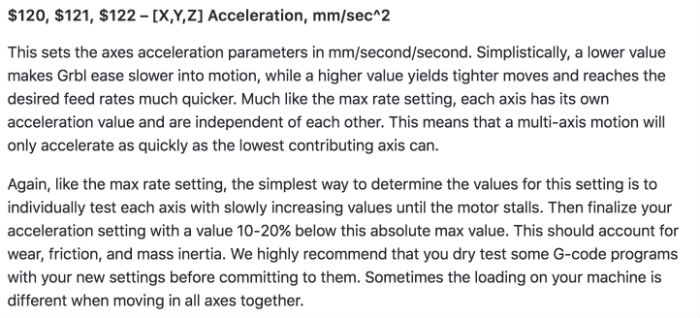
$120 and $121 are accel, mm/sec^2 of X, Y
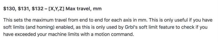
$130 and $131 are max travel, mm of X, Y
more informations are here
The height of template was about 230mm so we put 230 on $130 that is X’s max travel. And put ample distance like 1000mm on $131 because Y is rotating and we could not calculate the distance of template.
And we tried to find the approximate speed of each axis. We set X’s max rate 20mm/min and 700mm/min for Y. It turned right speed as we intended to. But when we moved both motor speed were changed. We couldn’t find the reason. So we modified max rate of both axis a lot of time. But we couldn’t find the golden ratio. These were videos of our failure.
Both X and Y were fast.
X was fine while Y was too fast.
Y was fine while X was little bit fast.
So we tried to measure speed by using stopwatch. X’s adequate speed was 20mm/min regardless of max rate. And Y’s adequate speed was 1turn/7sec.
PROBLEM SOLVING
After hundreds of trial, I found the reason why speed changes. We put X230 Y-400 for the distance because we thought it turns following max rate and distance wasn’t important. But when we put X230 Y-400, X’s max rate is 20mm/min and X couldn’t go over this rate and while X moves 230mm with 20mm/min fast, Y should move -400mm at the same period and it automatically slower the speed under max rate.
So we started from beginning again. First, we modified X step/mm. Default $100 was 250step/mm but when we moved 20mm it went 12mm.
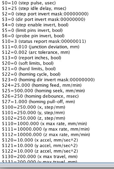
This is default setting.
After calculating steps to move 1mm was 416 steps to move 20mm. Then we tried again but it moved more than 20mm so we lower the step. Finally 397step was almost exact steps to move 1mm.

And we put 230 for X’s max travel that is height of templete. So we could control X’s speed, we put 20mm/min for max rate.
And we put 10000mm/min for Y’s max rate because we can control Y’s speed by distance. First we tried X230 Y-1500 but Y was still slow. Second was 2000 and it was still littlest slow. Finally X230 Y-2200 was right speed.
Video of Success
Here are my works.
Download