WEEK 3 - COMPUTER-CONTROLLED CUTTING
Assignment - group assignment:characterize your lasercutter, making test part(s) that vary cutting settings and dimensions
Here is the link to Group assignment.
individual assignment:cut something on the vinylcutter design, make, and document a parametric press-fit construction kit, accounting for the lasercutter kerf, which can be assembled in multiple ways
Vinyl Cutting
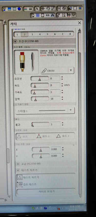
This is vinyl cutter in Seoul innovation fablab. Graphic cutting pro fc2250-60. And its software is graphic studio.
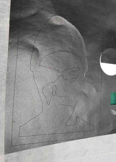
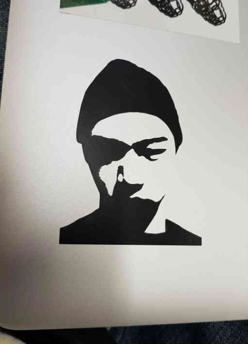
I tried to make a sticker of my face.
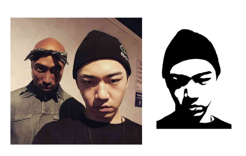
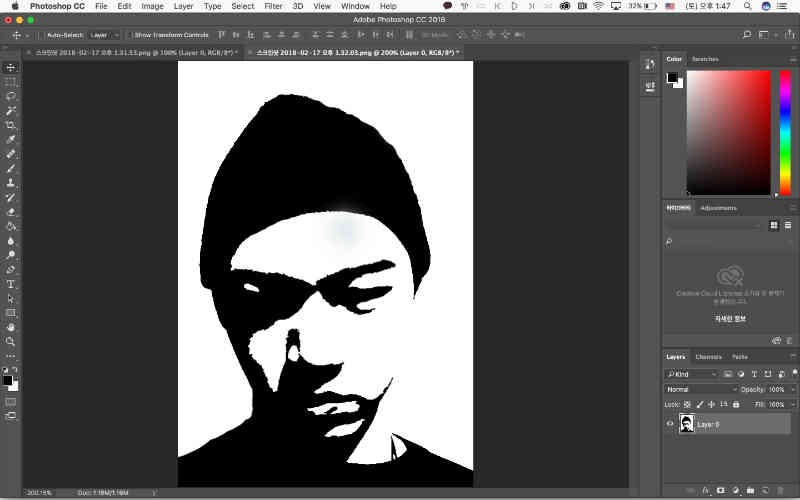
First, open the file at Photoshop. I adjusted level and curve to make stronger image contrast. Then made it grayscale to make it just white and black. I saved it jpg extension.
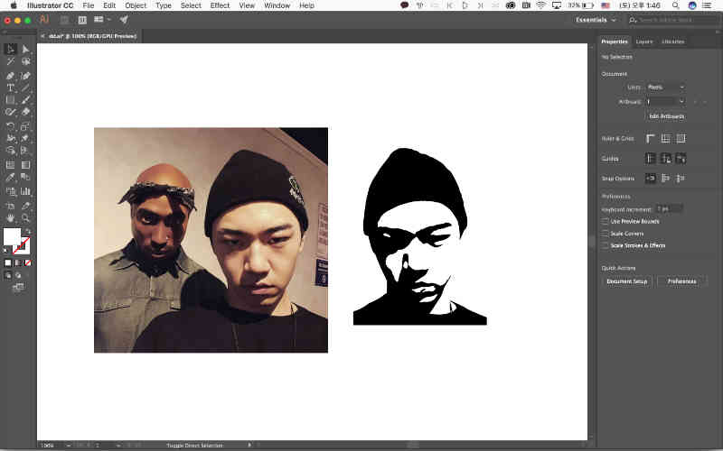
Second, I opened this file at Illustrator and did the image-trace to convert in vector path. Then I exported in dxf extension.
Ready for the vinyl cut. I opened this dxf file. Place and adjust the size on the working board. It creates its outer border itself.
I can set the speed and pressure of the cutting knife. After few tries. I found appropriate pressure and speed. It was 8cm/s for the speed and 18 for the pressure.
I tried on black label sheet.
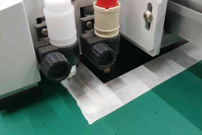
I placed the sheet on the machine and put some masking tape on every edges to hold tight and flat. Then I checked cutter is right and set the origin point manually. So that It will not get off the material.
Then push the start button, after working done, the knife goes edge of the table automatically.
I detached both of label sheet and masking tape together. And I detached whole sticker together to the border.
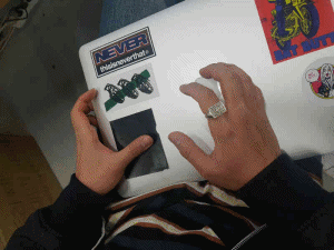
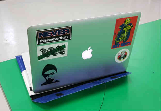
And attached them on the laptop together. Then I removed extra sticker to make it proper.
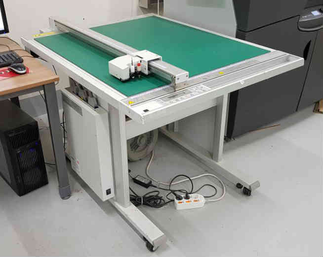
Laser Cutting
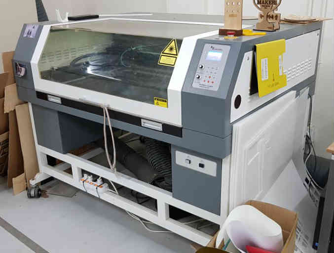
Laser machine
This is laser cutter in Seoul innovation fabled. K2C-X. And its software is golden laser cut&scan control application.
Characterizing group assignment
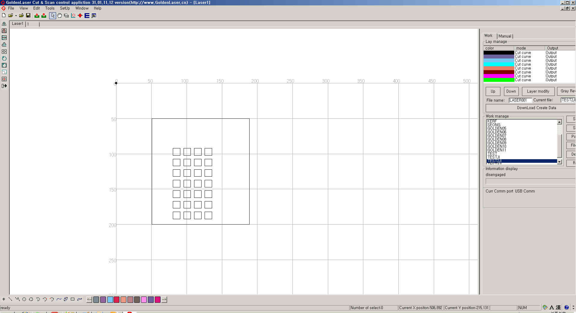
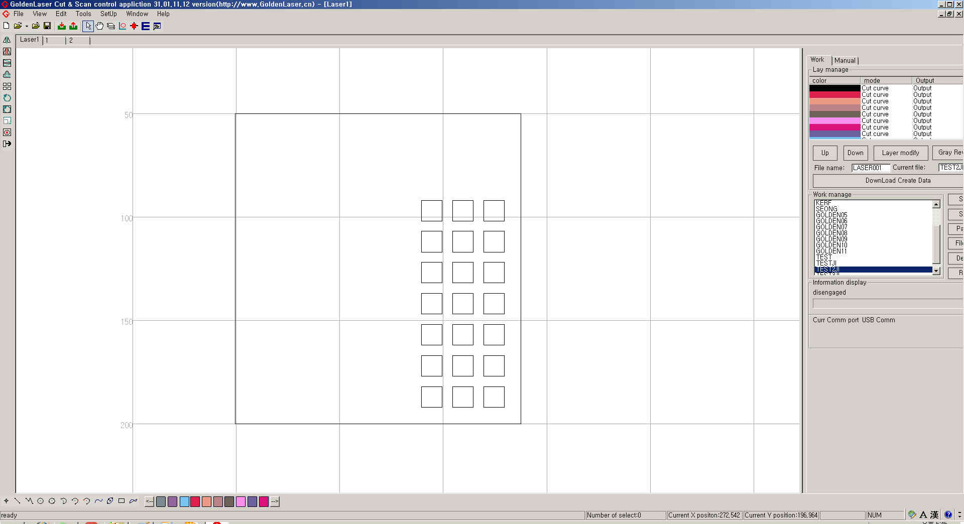
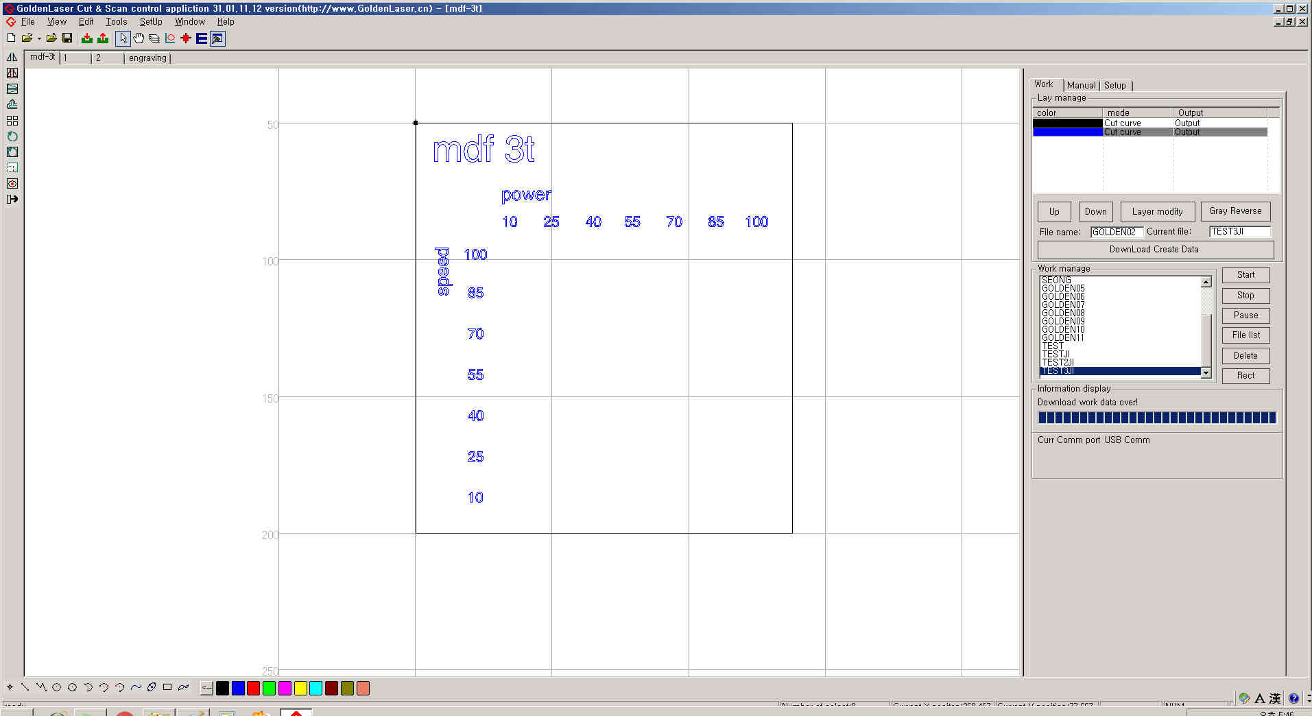
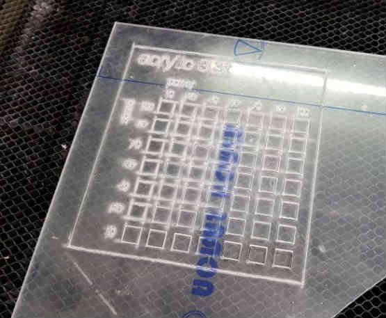
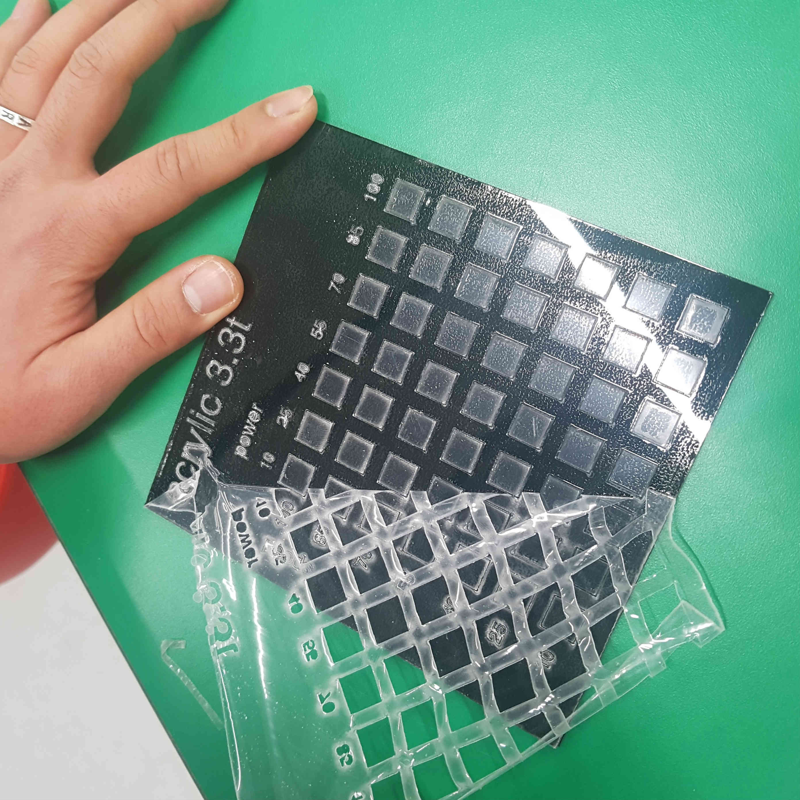
First, I drew some squares to do some experiment with various speed and power of laser. I tried power and speed value from 10 to 100 in units of 15. (10, 25, 40, 55, 70, 85, 100) Then here are 49 squares. I can get the results like a graph.
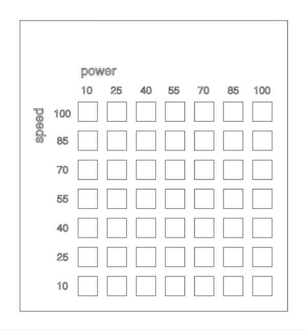
And I put some text about material and its thickness.
I saved this drawings in dxf extension.
(The software of laser cutter supports only 30 layers to make variables. So I separate the file two.)
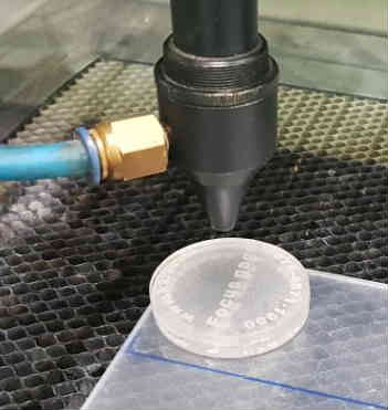
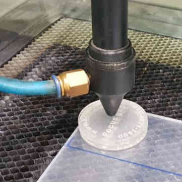
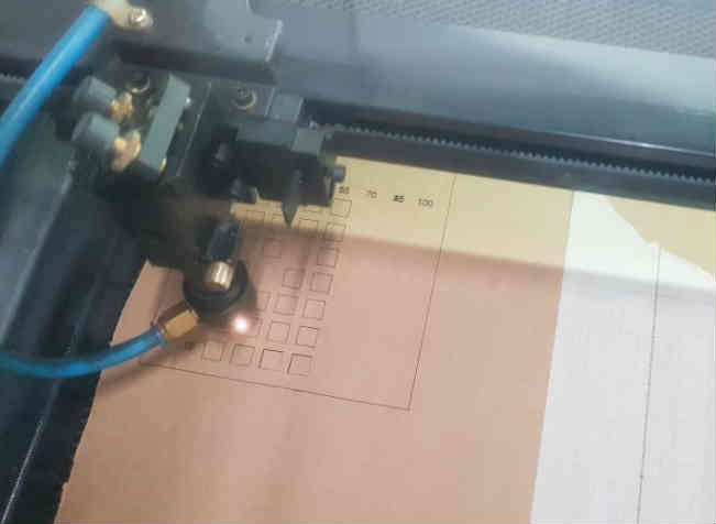
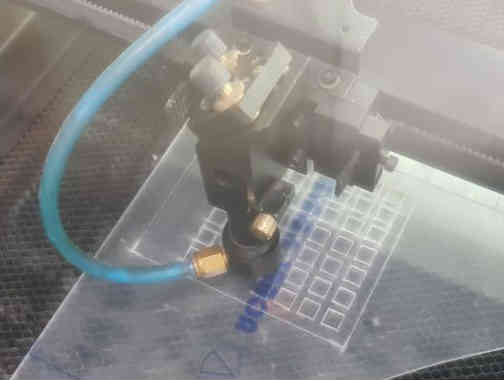
I opened file on laser cutter program and set material and origin point. For the set the height of laser, I put plastic like a coin on the material and unroll the bolt. Then output part of laser machine settled on the plastic. It’s proper height of the laser.
Then I can check the work area by pushing test button. If the area is fine, press the start button.
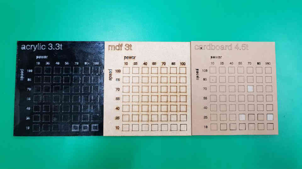
MDF 3t
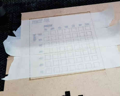
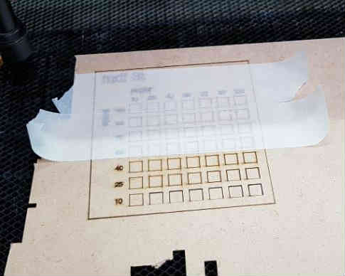
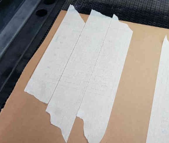
After cutting done, I should put it on the machine closed about 5 minutes for the ventilation machine gathering dust and gas. After, open the cover and put some masking tape to hold every parts.
i put masking tape on the backside and remove the tapes on the top.
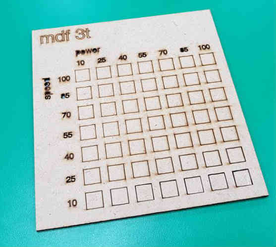
It shows MDF is being cut under speed 25 irrelevant to power. But I can notice the soot and burnt mark at speed 10 and power over 70.
It also has unnecessary thick kerf.
So I think ideal value for cutting MDF 3t is speed about 25, power about 70. And it’s enough for just marking at speed 100 and power 10. For engraving, up to speed 70 and power 40.
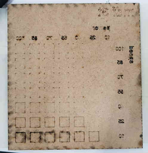
Cardboard 4.5t
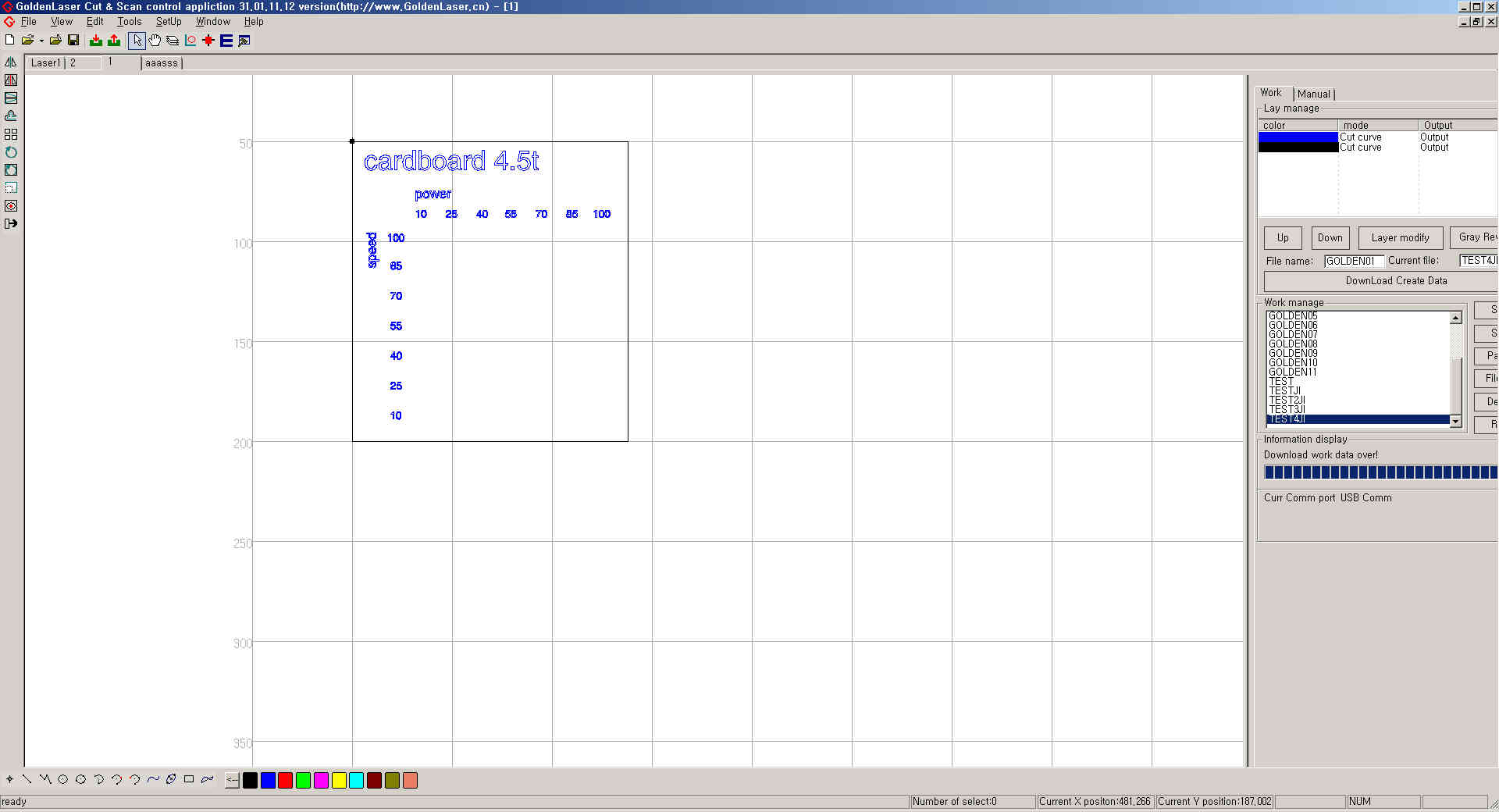
Same process with MDF (but, I did some mistake that I applied same file twice. So I tried again.)
It shows cutting was fine at speed 10~25 regardless of power. And at speed 40, power must be over 40 to cut surely. But, same as MDF, speed about 10 and power over 70 makes burn.
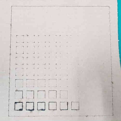
Also speed less than 25, power over 55 makes excessive thick kerf. I think ideal value for cutting cardboard 4.5t is speed about 40 and power about 55. It makes neat surface on both sides and appropriate kerf.
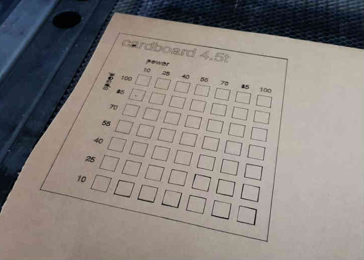
Acrylic 3.3t
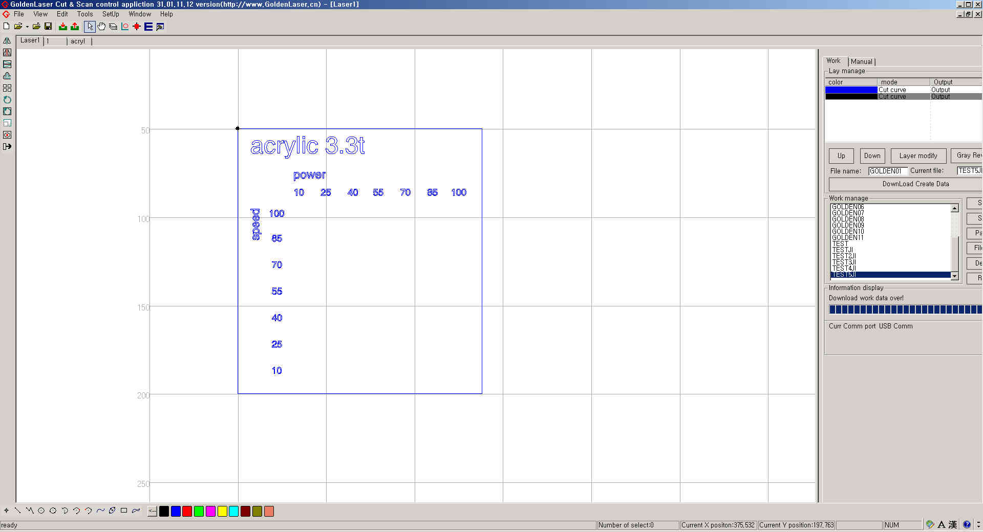
Same process with MDF and cardboard.
It shows cut will be fine when speed under 10. It makes burning mark on the backside masking film power over 70.
On acrylic, kerf was thicker and messer than mdd or cardboard regardless of speed and power.
I removed the masking film on surface.
I think speed 10, power 40 is ideal value for cutting acrylic 3.3t.
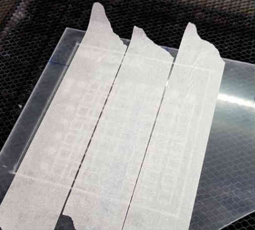
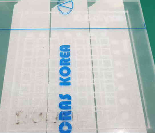
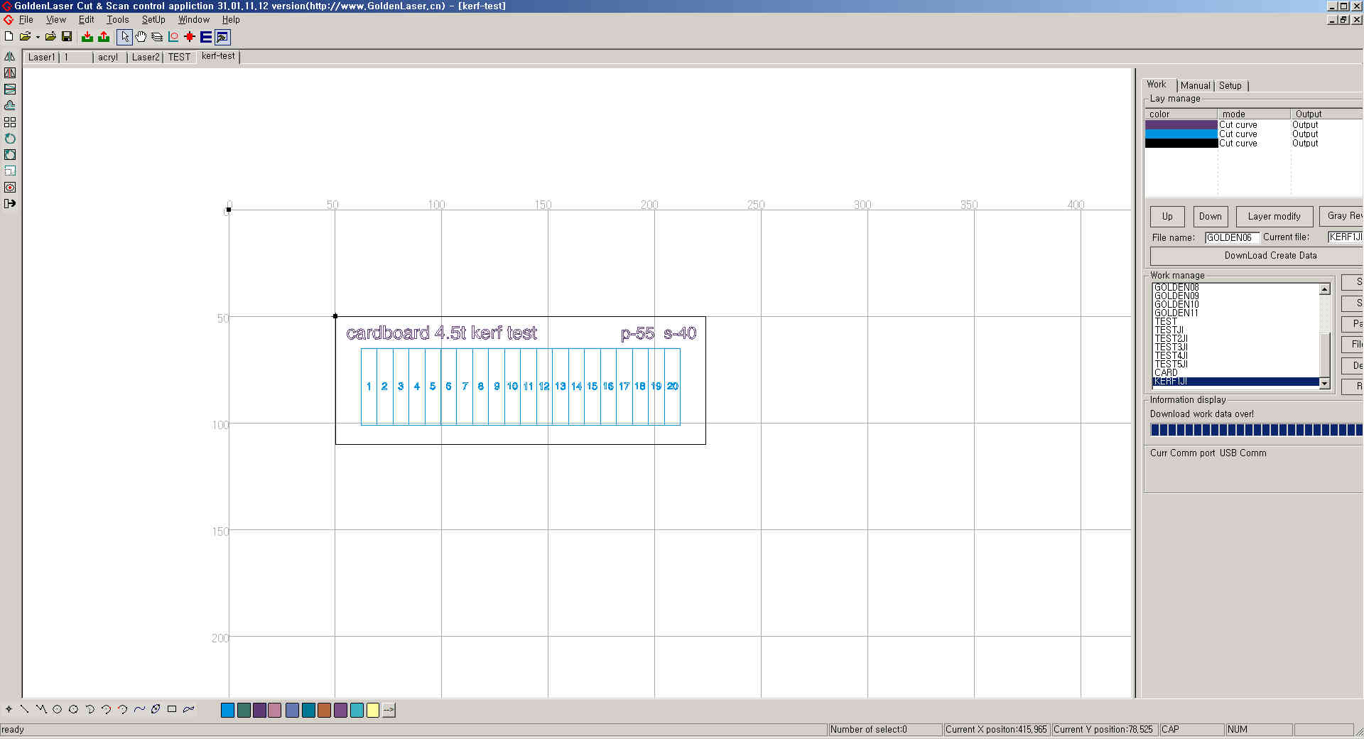
Finding kerf on card board 4.5t
I made one rectangular and 19 lines in the rectangular. So it looks like this 20 vertical rectangular. And I put some texts about material and values of speed and power.
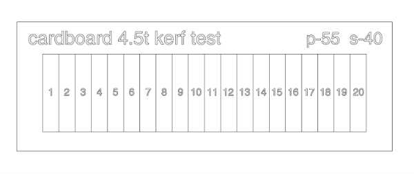
I saved this file in dxf extension. And proceed with former cutting works.
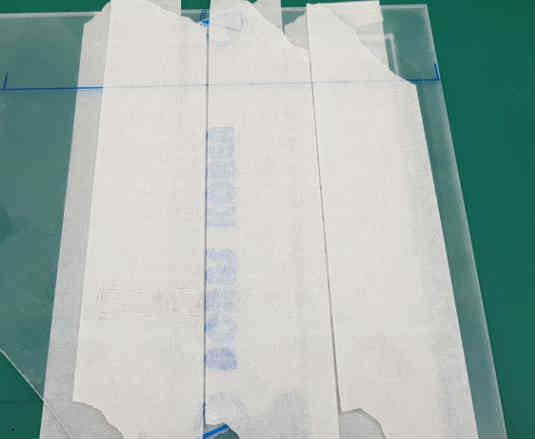
After cutting finished,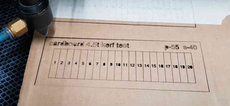
I put some masking tapes on it to hold those parts.
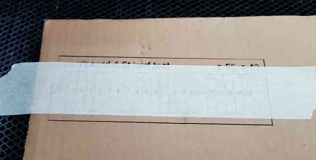
On the table, I removed tapes and push those parts close to the left.
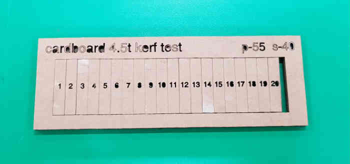
There is an aperture that 21 kerfs made. It was 4.3mm.
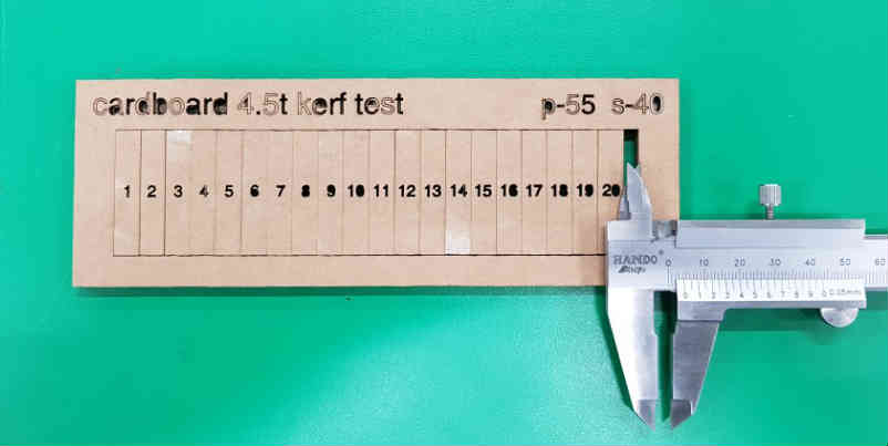
So, one kerf is 4.3/21mm that is 0.2mm approximately at speed 40, power 70.
Additionally, I found that ideal value(speed 40, power55 ) I think has error in various condition. It didn’t cut perfectly and I tried again at s-40,p-70. I need to do more experiment.
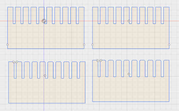
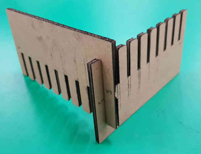
I tried to make combs that has simple slot and chamfer. Kerf was 0.2mm. So slot should be 4.1mm because material thickness is 4.5t. I made various slot thickness from 4.15mm to 4.5 units of 0.05.
With simple slot, it fits tight with thickness 4.05mm. and it has little gap with thickness 4.1mm. Over 4.1mm , those are too loose.
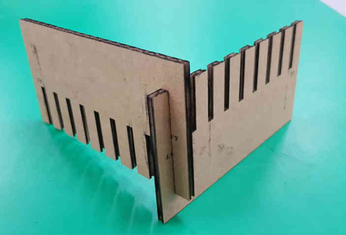
With chamfer, it fits tight with both thickness 4.05 and 4.1mm. And those are never fell apart even shaking hard.
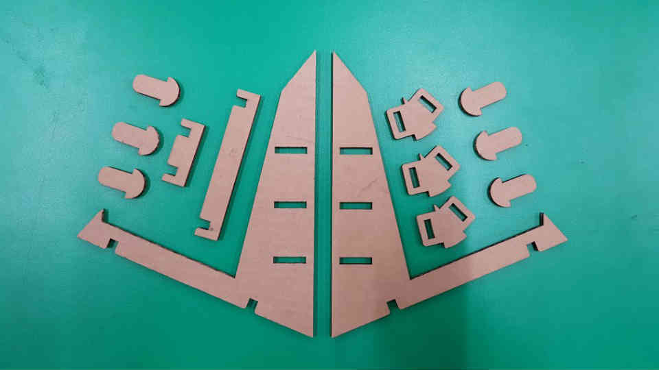
Parametric Design - Press fit kit
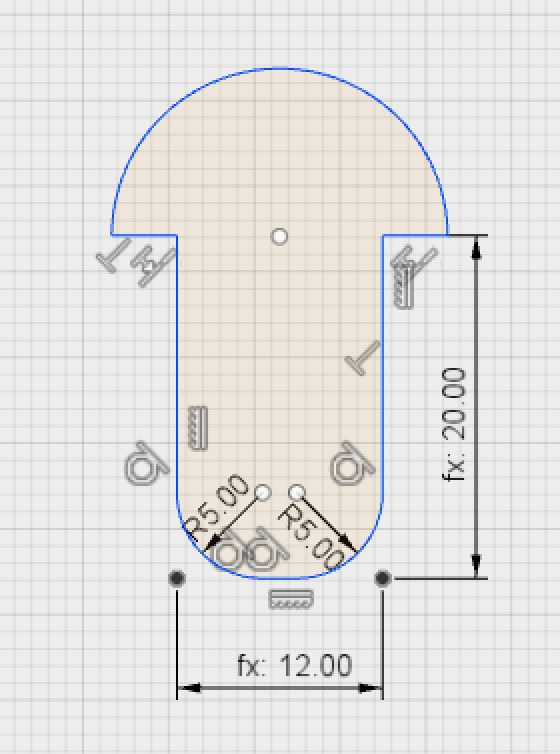
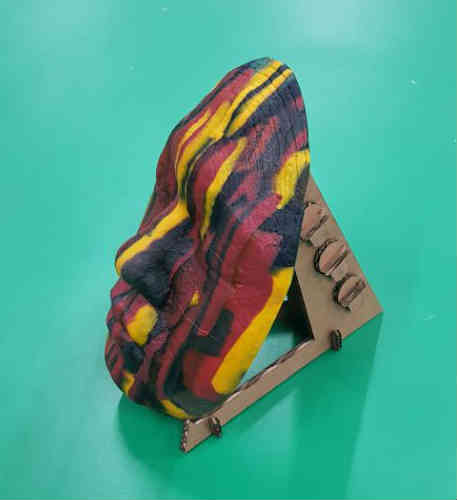
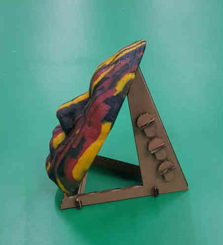
I decided to make holder for my former glass work.
First, I used familiar program Rhino to figure out the approximate form of the holder I would make. I seized the height and the angle of the holder.
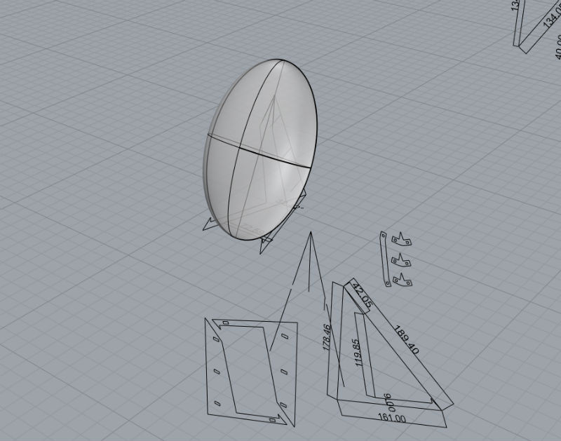
Based on these form, I decided to apply in Fusion 360.
I drew curves based Rhino.
There is ‘change to parameter’ in modify menu in fusion360.
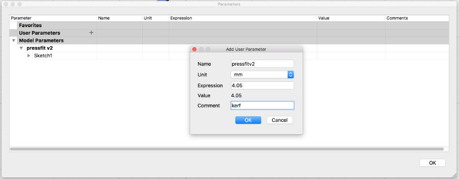
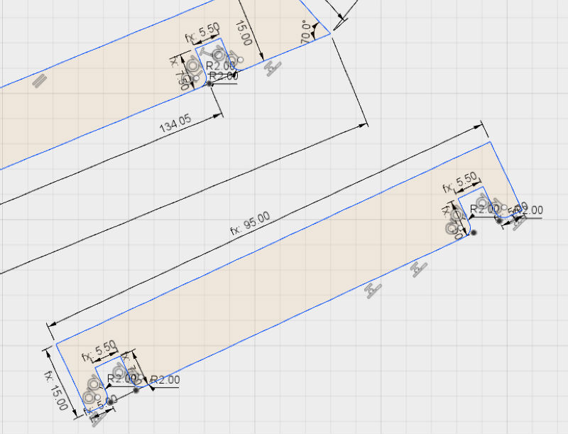
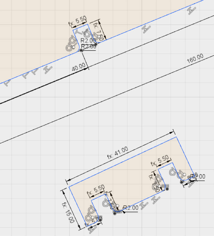
And I put every fixed value like kerf thickness I got 4.05mm, and kerf length, kerf depth, holder depth, length, thickness etc.
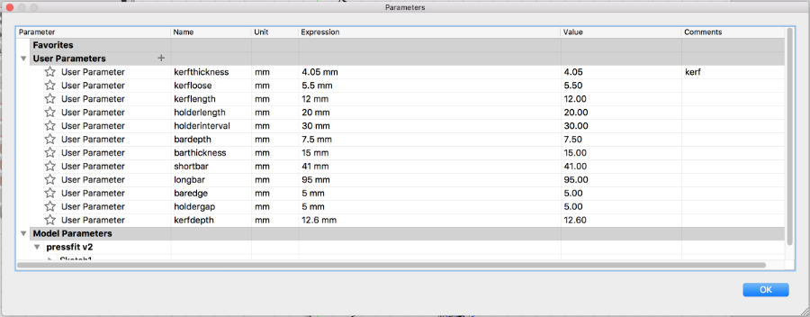
And I applied those parameter to my drawing as dimension. Then, it changed to fx: parameter value.
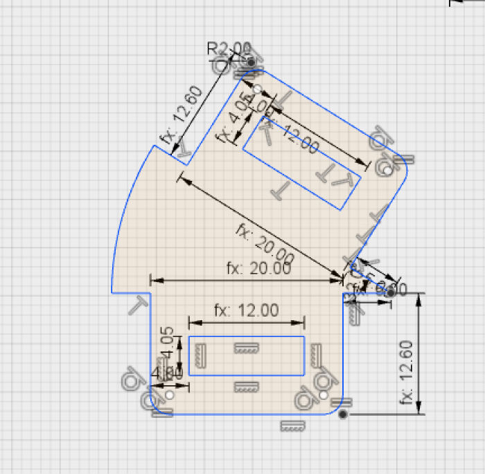
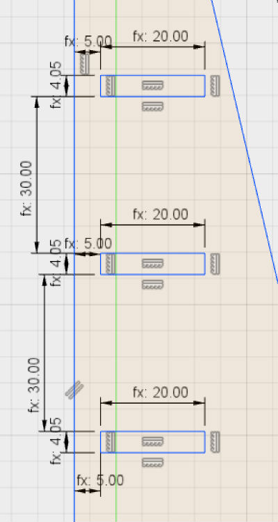
These are the image I applied parameters.
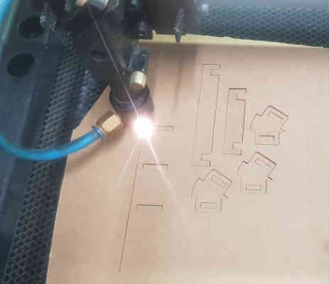
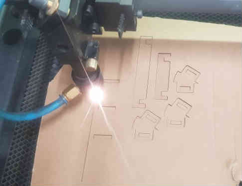
I exported this file to dxf extension file for laser cutting. This is the image in lasercutter program.
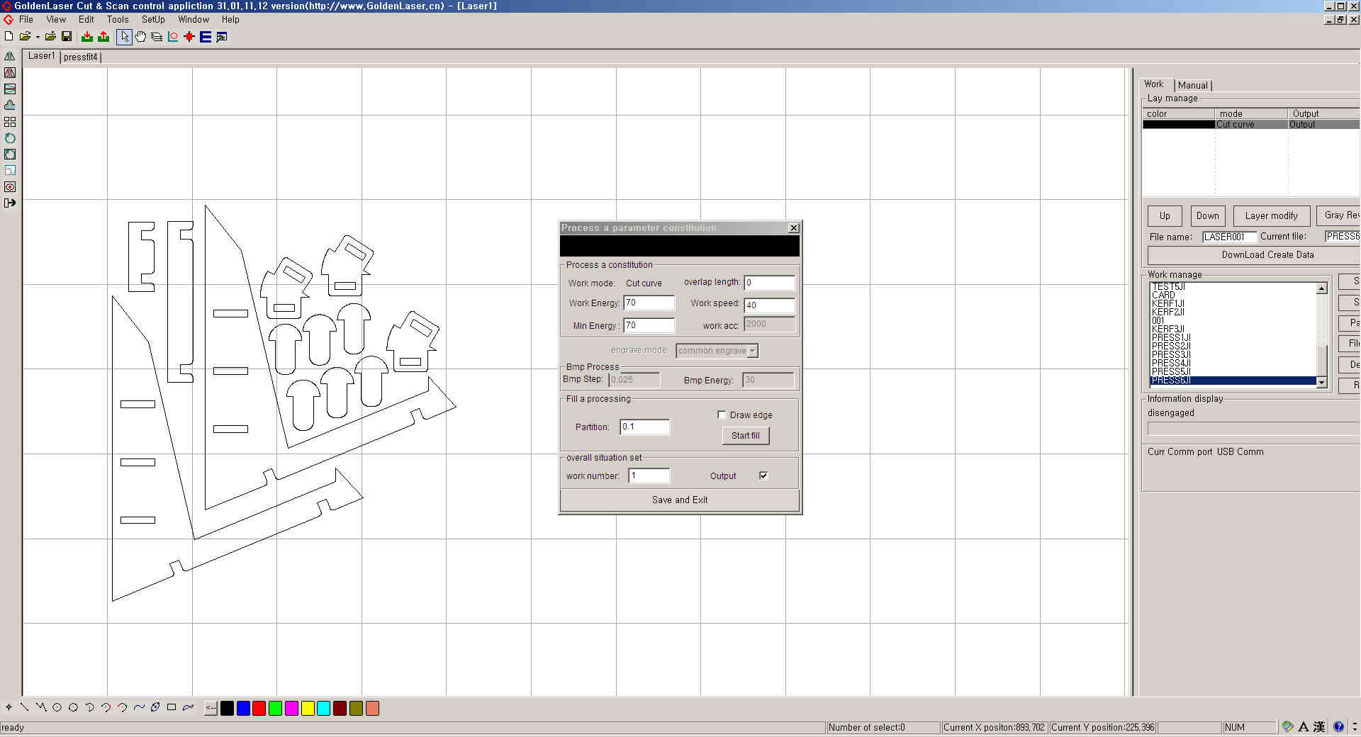
I put laser cutting speed and power value. and start cutting.
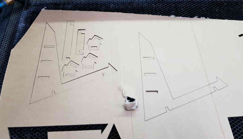
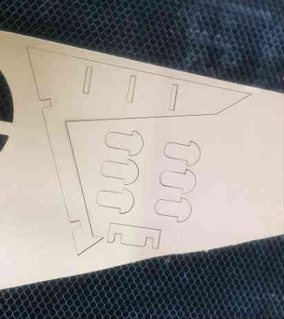
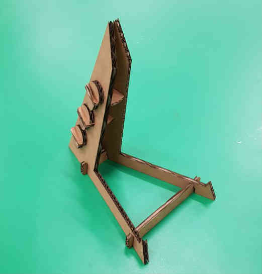
Here's pieces i cut.
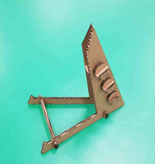
And, I assembled those pieces.
Here's picture holder with glass work.
Here are my works.
Download