WEEK 8 - EMBEDDED PROGRAMMING
Assignment
individual assignment :
read a microcontroller data sheet
program your board to do something,
with as many different programming languages
and programming environments as possible
group assignment :
compare the performance and development workflows
for other architectures
Here is the link to Group assignment.
DATA SHEET
It contain features of the MCU, the pinout diagram, pin configuration and description, architecture overview, register summary, assembly instruction set and many others information. There should be important information about the ATTiny board. I looked over the whole sheet. But only few pages, diagrams and images were understandable.
These are most important things I think.
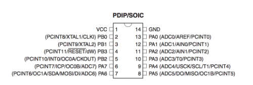
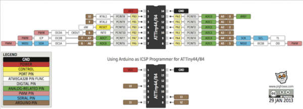
First, this is pin configuration that explains what is this pin does. Pin 1 and 14 are VCC and GND each. And, 4 is reset, and 7 is MOSI, 8 is MISO, and 9 is USCK.
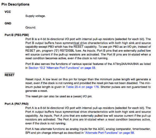
This is pin description that explain the rule of each pin. I was wondering about those terms at week6. I searched each terms that moment but I couldn’t understand exactly. But now I understand more than that days.
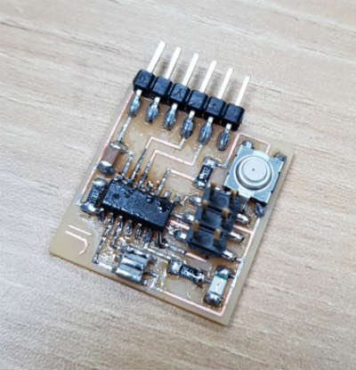
PROGRAMMING FAILS
At week6, I tried to program my hello board. I downloaded
Hello.ftdi.44.echo.c.make
Hello.ftdi.44.echo.c
Hello.ftdi.44.echo.asm.
Hello.ftdi.44.echo.asm.make
Hello.ftdi.44.echo.c.hex
Hello.ftdi.44.echo.interrupt.c
Hello.ftdi.44.echo.interrupt.c.make
Hello.ftdi.44.echo.out
These files which is Neil provided on class page. And I created folder named Hello and put those files. I followed tutorial so opened terminal and command
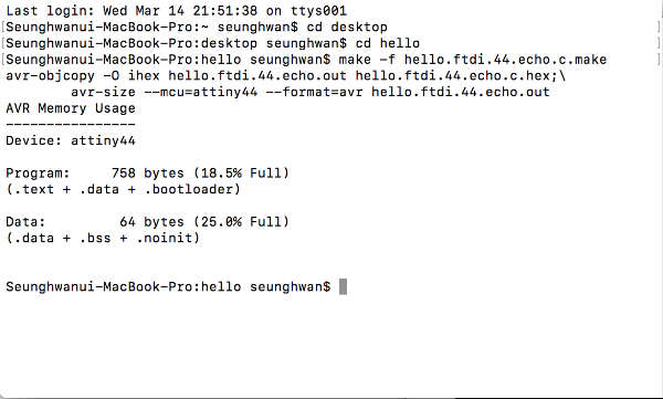
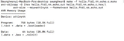
Make -f hello.ftdi.44.echo.c.make
it worked well like this image
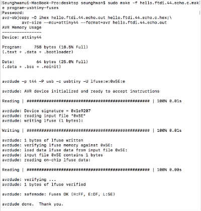
And I commanded
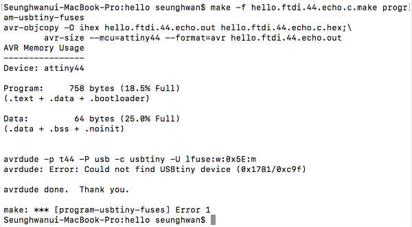
Sudo make -f hello.ftdi.44.echo.c.make program-usbtiny-fuses
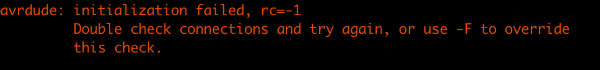
But it said ‘initialization failed’ and ‘check connection’. As the process I checked ISP board, I checked every components with multimeter. But there was no problem. I tried again but same message came up. I didn’t know the reason.
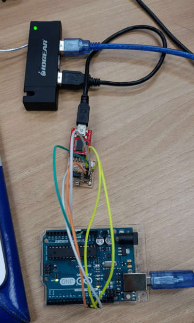
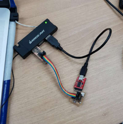
This is how I connected my hello board and ISP to computer. I didn’t know ftdi board and cable offer power to hello board.
I realized FTDI is essential to program the board after this week’s class. So I tried again with same files and process. But in the same point, it couldn’t read the usbtiny. So I checked the MacBook system report hardware. And it had connection problem. So I put the ISPboard again, then it read my usbtiny. I tried same command again. Buuuuuuut!!! It came up with the same error messages about connection. I was depressed to make hello board again.
ARDUINO
to understand programming I learned basic things of Arduino.
First I installed Arduino IDE which is open-source programming program. And I searched tutorial with LED and pushbutton. This is the linkof tutorial
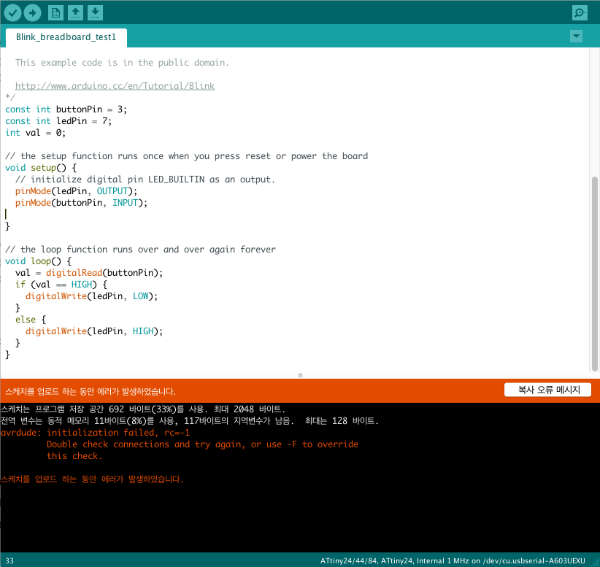
I opened example code on Arduino file/examples/Basic/Blink.
And modified the code following the tutorial. There are explain sentences next to the code that make easier to understand.
const int buttonPin = 2;
const int ledPin = 13;
int val = 0;
This codes defined which pin does the rule of some components. Then I can use the text rather than PIN number.
Const is code for something it never changes.
void setup() {
// initialize digital pin LED_BUILTIN as an output.
pinMode(ledPin, OUTPUT);
pinMode(buttonPin, INPUT);
}
these are for declare which pin is input and output.
void loop() {
val = digitalRead(buttonPin);
if (val == HIGH) {
digitalWrite(ledPin, LOW);
}
else {
digitalWrite(ledPin, HIGH);
}
}
These are for declare specific condition to make program do something.
After modifying codes, I checked if there are grammar problems or mistakes. I debugged and there was error message and it told me what the problem is. It was brace problem so I put ‘}’on appropriate position.
And I placed some components on bread board to do some practices. I put pushbutton and LED also two resistors. On breadboard, there are power line on the both sides of the board. And between those lines, there are many holes which is connected each other only horizontal way.
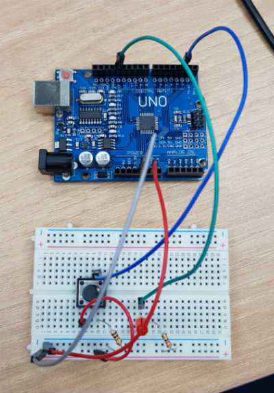
This is how I connected the breadboard and Arduino Uno.
VCC and GND to power line, and every components from power line and components to Arduino.
After I connected every parts, I push the upload button to program. If it worked well, the LED will be off when the button is not pushed. When press the button LED will shine.
In this process I understand more about program I think.
PROGRAMMING
Back to hello board.
I tried to program my hello board with Arduino as ISP. Because I did hundreds of time with FABISP. For programming ATTiny with Arduino IDE, I should download the informations and make IDE read ATTiny. I followed HighLowTech page. This is the
link
At Arduino preference I can get the information putting URL. I copied the address and bring information. And I could install ATTiny at board manager. Tool/Board/Board manager
I searched attend and install it. After install done, I could check the ATTiny on the board list.
One more thing to use Arduino as ISP is programming. There is example code on File/example/ISP/Arduino ISP. Open the code and upload to Arduino uno.
And i connected Arduino and hello board. Following this image.
It says which pin of ATTiny is connected to which pin of Arduino.
It’s like this. So I opened Eagle’s board file and connected Uno and 6pin header.
• Uno —>FabISP
• 10 --> Reset
• 11 --> MOSI
• 12 --> MISO
• 13 --> SCK
• 5V --> VCC
• GND --> GND
And I selected board, processor, clock, port and programmer. Like these
• Board: ATtiny 24/44/84
• Processor: ATtiny44
• Clock: 20 Mhz (External)
• Port:
• Programmer: Arduino as ISP
const int buttonPin = 2;
const int ledPin = 13;
int val = 0;
void setup() {
// initialize digital pin LED_BUILTIN as an output.
pinMode(ledPin, OUTPUT);
pinMode(buttonPin, INPUT);
}
void loop() {
val = digitalRead(buttonPin);
if (val == HIGH) {
digitalWrite(ledPin, LOW);
}
else {
digitalWrite(ledPin, HIGH);
}
}
I modified the code to right PIN number and uploaded. But it said double-check connection..
PROBLEM SOLVING
I was convinced with connection and soldering until this moment. I asked instructor with this problem.
He advised with several problem and struggled with me to solve the problem. After several trials, he found prior years student’s problem solving documentation. It was about shorts under the MCU on the board. So I checked my board but I couldn’t see under the MCU. So I checked again my board design at Eagle. It was fine and I checked path on fabmodule. Then I found.
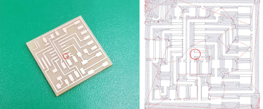
Pin8 was connected to USCK which is connected with pin9. Path wasn’t created and remained pin8 connected. To solve this problem I should desolder MCU.
This is how desolder MCU. Put lots of lead and make lead droplets and make it maintain heat. Make the leads melted and remove MCU. And using lead inhaler and solderwick to remove remain lead. It was connected.
I separated those part with cutting knife.
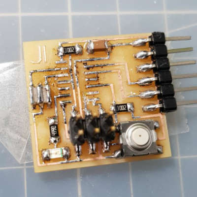
And resoldered MCU.
PROGRAMMING WITH C-CODE
I connected to my FabISP and FTDI cable to programmed with Neil's C-code.
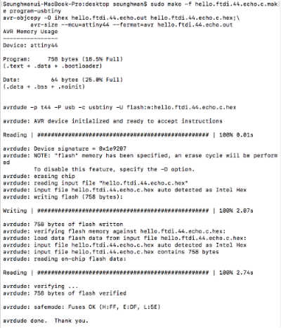
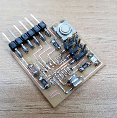
Programmed successfully!!
It BLINKKKKK!!!!!
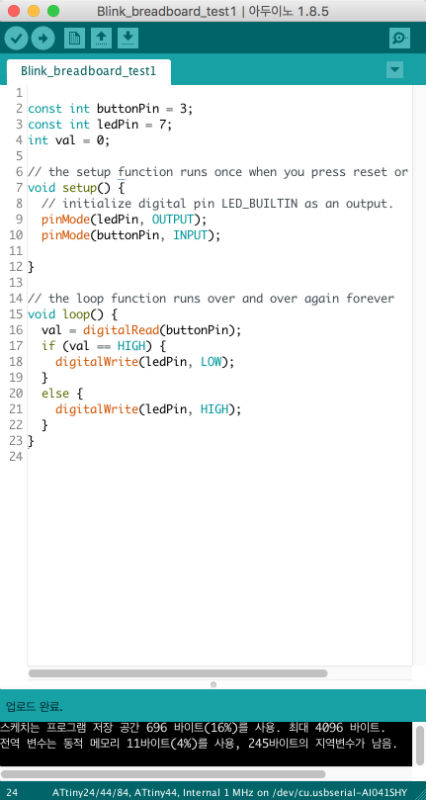
PROGRAMMING WITH ARDUINO IDE
Same as C-code, I connected to my FabISP and programmed with Arduino IDE. It worked well.
Here's the arduino code.
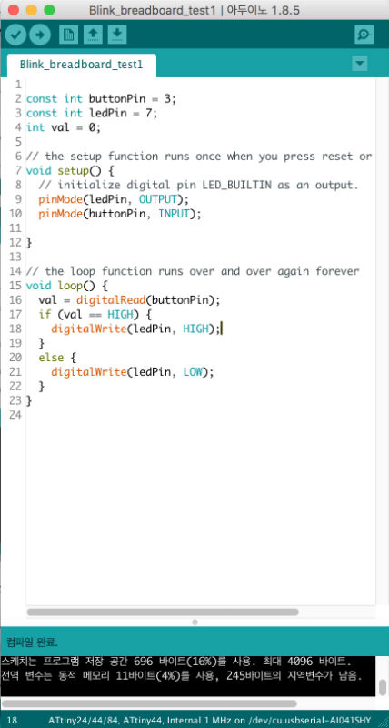
Also I tried another code.
I reversed reaction. When I pushed the button, LED off.
Here's the arduino code.
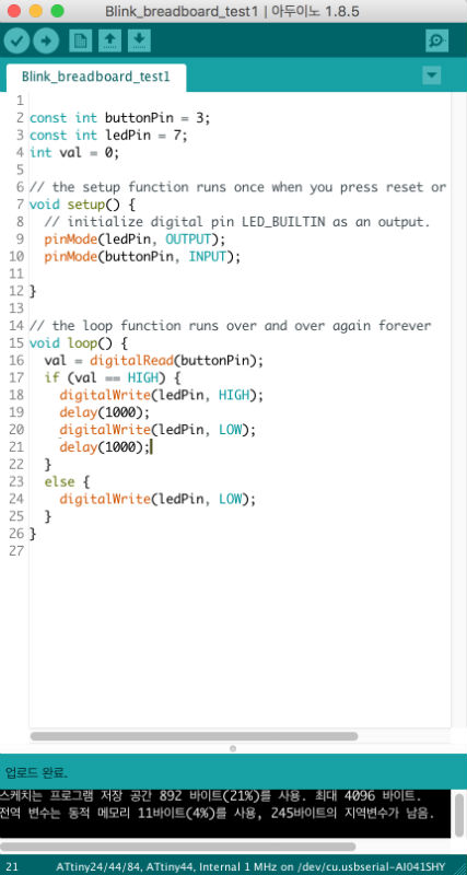
I wrote delay code to make LED blink in 1 second. and when I push the button LED will turned off.
Here's the arduino code.
Here are my works.
Download