
|
|---|
Assignment |
Final Project |
About Me |
|---|
Week 7
0. Assignment
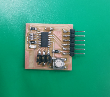
redraw the echo hello-world board, add (at least) a button and LED (with current-limiting resistor)
check the design rules, make it, and test it
extra credit: simulate its operation, render it
1. Redraw the echo hello-world board
Before redrawing the board, I had to install a program called EAGLE.
EAGLE is an abbreviation of 'Easily Application Graphical Layout Editor'
After installing EAGLE, you should load the library for a list of parts to use for your assignments.
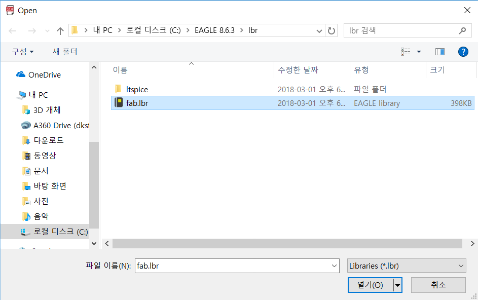
Download fab.lbr file.
(Right-click the lbr link and select Save As.)
Move the downloaded lbr file to C: Eagle folder(For version 8, Eagle 8.X.X) - lbr
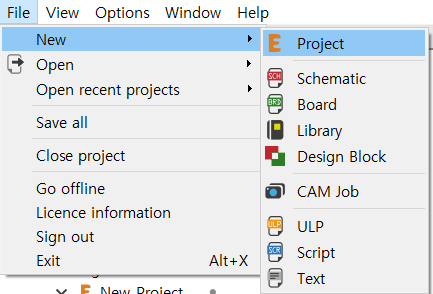
Open the EAGLE, File - New - Project
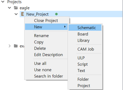
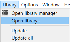
3. New - Schematic (On SCH(schematic page)) library - open library - fab.lbr
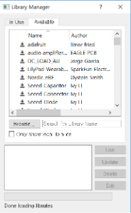
(On SCH(schematic page)) library - open library manager - Avaliable tab - fab - Use
Click add icon or type add on schematic page.
From fab library, choose proper components(with the same name, same functionality, they might be different), and display them.
Parts list to use
Attiny44 - Attiny44-SSU (vcc-circle)
AVRISP - AVRISPSMD(6pin ISP)
Cap-unpolarized - Cap-unpolarized C1206
FTDI-SMD-header
Res-US - Res-US1206
Resonator(crystal:middle should be connected to GND, The part used for soldering is 20MHz specification.)
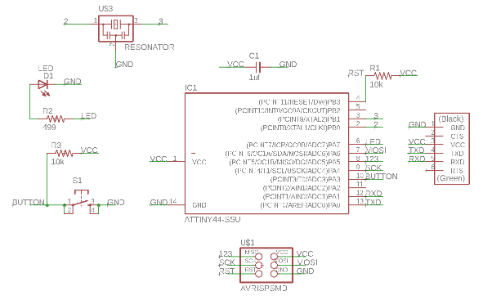
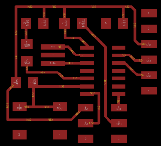
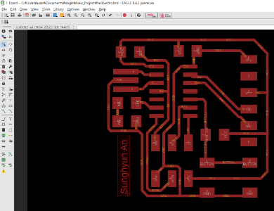
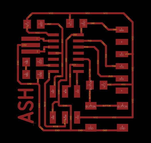
This is my schematic page.
You can use 'net'function to connect the line, or subtract the line shortly, and use the 'label'fuction to meet the desired line.
Also you can set the name to appear on the line using the 'name' function.
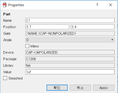
You can change the name and value of the part using the 'Info' function.
 |  |
|---|
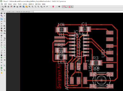
If you have connected the components in the schematic, you will see a yellow line on the board page.
In this page, you can not connect the unconnected parts in the schematic.
When you connect, you can connect using 'ROUTE' function and you can delete line with 'RIPUP' function.
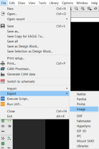
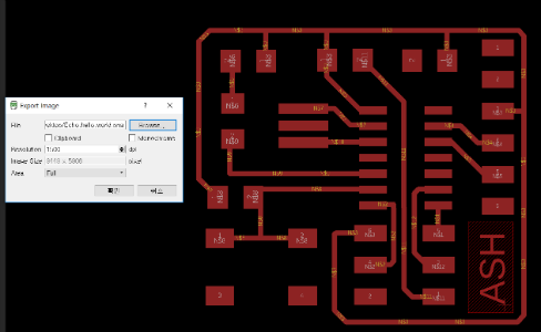
When the circuit is completed and exported to black and white png, File - Export - Image - export location, dpi and monocrome must be checked.
If the area is full, the entire copperboard is exported, and the window exports a portion of the copperboard that is currently visible and is convenient for you.
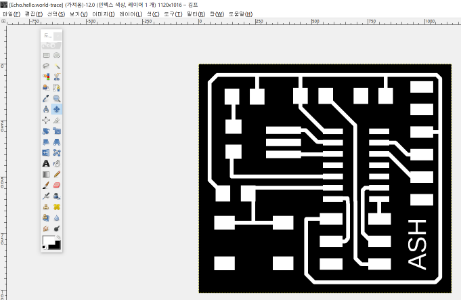
I used the GIMP when adjusting the circuit size, and I was unfamiliar with it, so I had difficulty in how to use the function. Also, I tried to use mspaint which is a windows basic program, but I did not use it because it was impossible to control the dpi and the result was hard to come out.
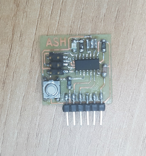
But I found a big mistake. After exporting, I checked to see if there was any mistake before milling. I found the unconnected parts in the schematic and rebuilt the circuit. What I felt in the part of reprocessing was that I only needed to have more than one circuit. But I think it was the most intensive work I've done this week.
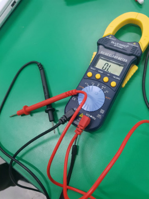
I checked with a multimeter, but there was a short, and I added a wrong circuit to make a new board.
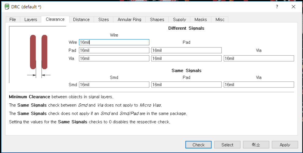
I did not check the DRC while creating a new board, so I tried this one.

I checked all the values by applying 16mill and proceeded because there was no problem.
You can download my work here
zip file download