WEEK 7 - Electronics Design
Dario Bernabini, Tommaso Lombardi, Giada Allocca, Eleonora Piccinelli, Giuseppe Allocca, Antonio GarosiIndex
While thinking about what to accomplish for this group assignment, we realized that actually we already put in action what was required several times in the weeks before, specifically every time we had to check how we did a soldering work.
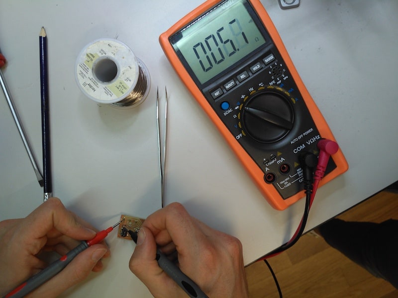
For example, for making the Hello Board we, since it was our first try at soldering, we often resorted to a multimeter in order to check things such as failed or unwanted connections, the functioning of a capacitor, the direction of an LED or, as in the example below, the real value of a resistance
Concerning the microcontroller, checking it with a multimeter set on "Continuity" mode is a very good practice to see if the pins are well soldered to the board of if there are any unvolotary shortcircuist among different pins or tracks. This is simply done by justaposing the multimeter probes on the desiderd pin and check the expected result. Applying this measure every time one has finished soldering a controller can reveal immediately eventual mistakes and save a lot of hassles.
A fun test we did was to power the board with a desktop voltage supply and variate the volt values to see if it worked properly or not.
After flashing on a Hello Board a simple led blinking code, we started varying the voltage from 0 to 5.
The clip belows shows a the controller in full activity as soon as we reached around 3.3 v, which is what we expected since it is exactly what declared on the ATtiny 45 datasheet.
Inibited by the fear of being yelled at by our instructors, we had not the courage to drive the current above 5 volts risking of irremediably waste the controller.