Week 13 - Networking and Communications
Assignment
Individual assignment
design and build a wired &/or wireless network connecting at least two processors
Group assignment
send a message between two projects
Process
After trying and understanding serial communication in my previous assignments, I wanted to go deeper in the world of serial protocols and test one that was best optimized for simple boards and circuits. The choice fell upon I2C exactly for this reason, since essentially it’s a communication protocol that requires only 2 wires and everything else is left to the software side.
Understanding I2C
The very first step I took in the world of I2C was to read a good technical tutorial by SparkFun which explains in great detail how this protocol works. Specifically, the following image resumes all that is needed to grasp I2C and start to put it at use.
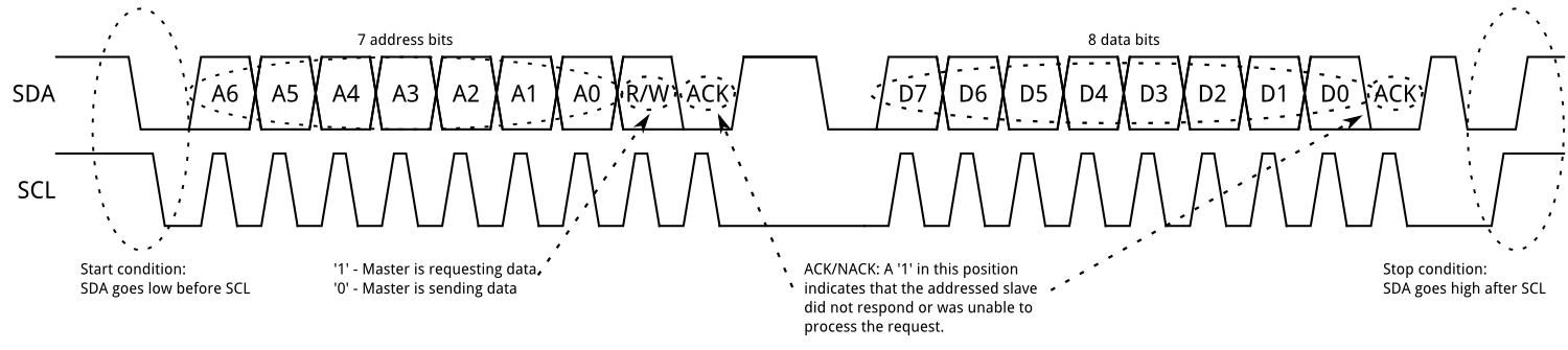
The above image depicts the framework of standard I2C communication, meaning the form data are organized in order to be readable by the network. In a world in which there’s a software library for (almost) anything, it might seem a bit of of an overkill to read certain techincal details, but actually ignoring them would be much, much more detrimental, especially in debug stages or while working with controllers that aren’t well documented yet. Furthermore, if you’re going to design your own network’s boards, it’s fundamental to understand the hardware layer which will make your communication possible.
In my case, I indeed ended up using a couple of useful library, but passing through this stage helped me understand clearfully what I was working on every level.
Testing I2C communication with an Arduino Uno and the Hello Board
To put the protocol at work at first I delved into the Arduino Wire library, which covers all that is needed to implement I2C and TWI communication between Arduino boards. This library emulates the functions and behaviours of Arduino Serial, and in fact most of the methods have the same name and return.
To get use of the slave/master mechanic of I2C, Wire also provides the following functions:
requestFrom(): for a master to request data bytes from a slave device;onReceive(handler): for a slave to register the functionhandlerto call when a master sends aintparameter;onRequest(handler): for a slave to register the functionhandlerto call when a master ask without parameters to perform;
This library was good enough to do the jobs inside an Arduino board, but I needed as well something to work on other boards with different microcontrollers. For this purpose, I found the versatile TinyWireM library by Adafruit which adapts the same commands of Wire to the SCK and SCA pin of every board in the Atmel ATtiny family. In this way I was able to use even other boards I previously fabricated to accomplish a full I2C communication.
Taking reference from the examples given by the libraries mentioned, I wrote two programs for two separate boards: an Arduino and the renowned Hello Board. The Hello Board would act as master in the communication and send a character increasing in value every second, the Arduino instead would read the communication and send it to the serial port.
This is the code for the slave Arduino:
#include <Wire.h>

void setup() {
Serial.begin(9600);
Wire.begin(1); //assigned slave address 1
Wire.onReceive(i2cRead);
}

void loop() {
}

void i2cRead(int bytes) {
  char c;
  while (Wire.available() > 0) {
    c = Wire.read();
    Serial.print(c);
  }
  Serial.print("\n"); //newline
}
This is the code for the master Hello Board
#include <TinyWireM.h>
#include <USI_TWI_Master.h> //library with many define used by TinyWireM

int led = 8;
byte x;

void setup() {
TinyWireM.begin(); //no address required for master
pinMode(2, OUTPUT);
}

void loop() {
TinyWireM.beginTransmission(1);
TinyWireM.write(x);
TinyWireM.endTransmission();
x++;

//fancy LED blinking according to byte just sent
for (short i = 0; i < 7; i++) {
digitalWrite(led, bitRead(x, i));
delay (100);
}
digitalWrite(led, LOW);
delay(200);
}
After flashing the boards, I connected them via the SDA and SCK pins, which also pass through 4.7 Kohm pull-up resistors and the 5V source as mandated by the I2C implementation (this is because the wires used to communicate have to be always high unless they’re driven low by the controllers - for example, to start the communication, send 0 bits or articulate clock’s ticks. To mention what previously stated, hardly I would have understood and remembered this feature if I hadn’t read the technical description of I2C).

Opening the serial monitor of the Arduino IDE showed me that the boards were communicating clearly and as expected.

Commanding boards through I2C
At first I thought that there was no big need of networking techniques in my final project, but as soon as I approached it I figured that they could have been of great, great help.
What I realized is that I wanted several different system running at the same time, but with different synchronizations. Instead of figuring out a complex core code managing it all, I thought it would have been much more efficient to have dedicated boards to separated systems and connect them via network. This would also allow me to work independetly on different features of my final project and easily extend it in case I wanted more features.
That’s I why, I designed the core board of my final project to be the master of an I2C network. In the image below, I highlighted the pins on the board that I have used to connect to the network.

An example of independent but connected feature of the system is what I devised for the speaker control. I designed a board a completely self-functioning board with an ATtiny45 controller but I also provided two pins for the I2C network, as it’s possible to see in the image below.

What I wanted to achieve was to have a the core board to communicate to the speaker board and give it orders. The latter would answer then back with a proper message. In this way, any board with an I2C connection could become a feature of my system.
So, I devised a couple of script - one for the core board and the other for the speaker board - to see if they were able to communicate. The LED I put on both would help me check the correct functioning.
The following is the code for the core board. In it, I send in loop an increasing number and gets one in response, then I flash the blink as many time as the given number is.
#include "Wire.h"
#define led 8

int i = 1;

void Blink(int n) {
	for (int k = 0; k < n; k++) {
    	digitalWrite(led, HIGH);
    	delay(400);
    	digitalWrite(led, LOW);
 		delay(400);
	}
}

void setup() {
	pinMode(led, OUTPUT);

	Wire.begin(); //master
}

void loop() {

//Set blink duration
	Wire.beginTransmission(1); //start communication with device addressed #1
  	Wire.write(i);
  	Wire.endTransmission();

//Ask for blink and blink in response
  	Wire.requestFrom(1,1); //1 byte from 1
  	while (Wire.available()) {
  		int c = Wire.read();
		if (c == 1) {
			Blink(i);
		}
  	}

  	if (i > 5) {
		i = 1;
  	} else {
  		i++;
  	}
}
The following is the code for the speaker board. Consider that in this case I used a Arduino-compatible library found on GitHub called TinyWireS.h by nadavmatalon, which isn’t official (actually, none is since none follows in full I2C requirements), but it was the most efficient I found and worked just fine for me (expect for something that has to do with the clock rescaling, making me refactor the times for blinking up to 12 times. Once understood, it was no more an inconvenient).
#include <TinyWireS.h>
#define led 4

int t;

void Blink(int n) {
  	for (int k = 0; k < n; k++) {
    	digitalWrite(led, HIGH);
    	delay(400);
    	digitalWrite(led, LOW);
    	delay(400);
  	}
}

void DoBlink() {
  	Blink(t);
  	TinyWireS.write(`1`); //sends a byte to master
}

void SetBlink(int x) {
  	while (1 < TinyWireS.available()) {
    	t = TinyWireS.read();
   }
}

void setup() {
  	pinMode(led, OUTPUT);

  	TinyWireS.begin(1); //slave address 1
  	TinyWireS.onRequest(Blink);
  	TinyWireS.onReceive(SetBink);
}

void loop() {
//empty
}
This codes makes it so that the the core board communicates to the speaker board a number, the speaker board flashes its led that number of time and send back a confirm message, then the core board flashes itself its led that times.
Result
Here’s a clip of both boards networked and working according the codes I wrote for them.

The design files of both boards can be found on the Final Project documentation.
Here the links for the codes of this assignment:
Gist & Further development
Making use of libraries is absolutely the easiest way to try different protocols quickly, even if you find not recently updated resources on which you have to hardcode something. But still you have to consider what hardware you have in your hands, how to use it and what result you want to obtain. In the end, it’s not really complicated to get things to communicate with each other, as long as you know what you want them to say and hear.
Making things communicate can be an essential part of a system, especially for purposes like testing and debugging, but also for extending functionalities and implement complex structures. Saving room in your project for network requirements can also make you save both time and migraines.
Tools and softwares used
- Arduino IDE
- Arduino Uno
- Previously made custom boards