WEEK 7: COMPUTER-CONTROLLED MACHINING
Objectives
Group assignment:Have I...?
MY OBJECT
When I thought about creating something big, I started looking for something useful and my attention was caught by this scene:
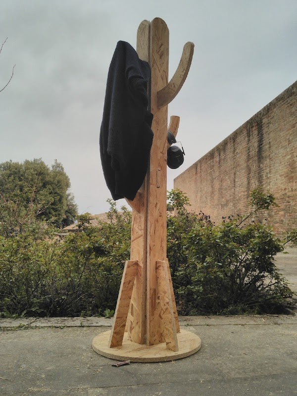
We definitely need an hallstand at home!
So, I decided to create a new one with a cartoon cactus inspired design.

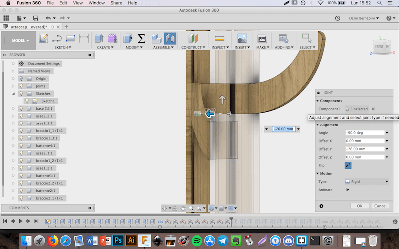
So, I opened Fusion 360 and I started modeling it using principles I learned during Week 4 and Week 6. I projected my firts strucure as:
During my test, I also produced a small prototype with the laser cutter machine (see Week 3). In this way, I would have seen possible problems related to joins, dimensions and so on.
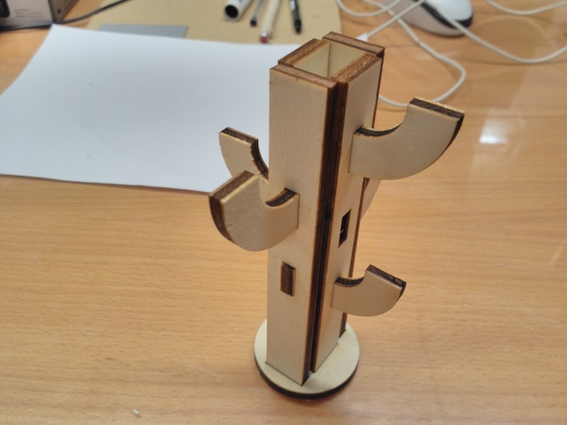
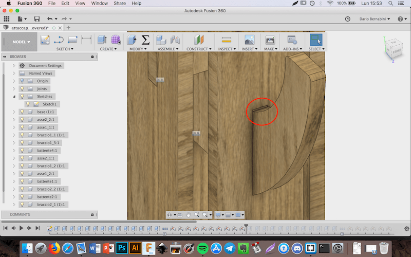
Basically, I've found two main issues:
And there the result:
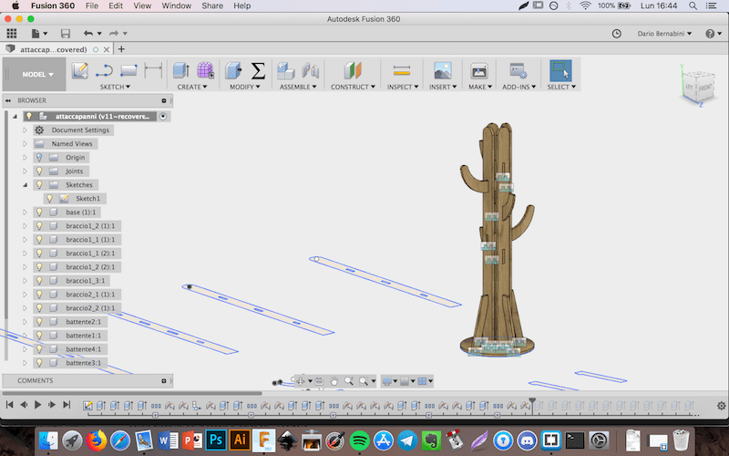
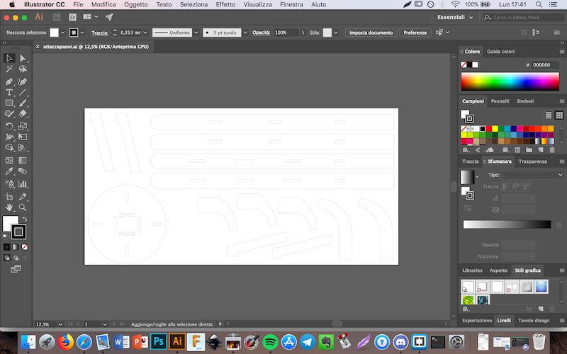
Once I noticed that every parts joint well, I exported my sketch as DXF and I opened Adobe Illustrator.
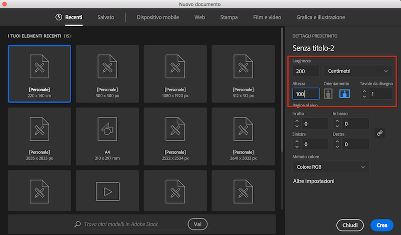
Here I make a new file with smaller dimensions than my OBS board (250 x 150 cm): I set 200 x 110 cm.
Than I clicked on
File - Open and I opened my DXF file in a new tab. I selected every piece in the DXF file just opened, I copied them and I pasted them in my 200 x 100 cm clean document.
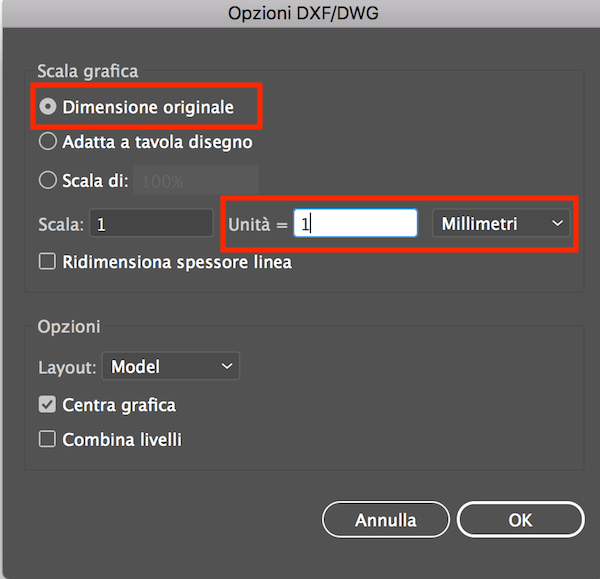
I had to take these simple steps to keep the measures of my project unchanged. Infact I opened my DXF with settingsAnd after some movements:Original dimensionsandScale: 1:1 millimeters
In this case I'm pretty sure not only that the area of my pieces is smaller than the OBS table area, but also that I can leave a good amount of space to securely fix the OBS table to the plate.
PREPARING FILE FOR SHOPBOT MACHINE
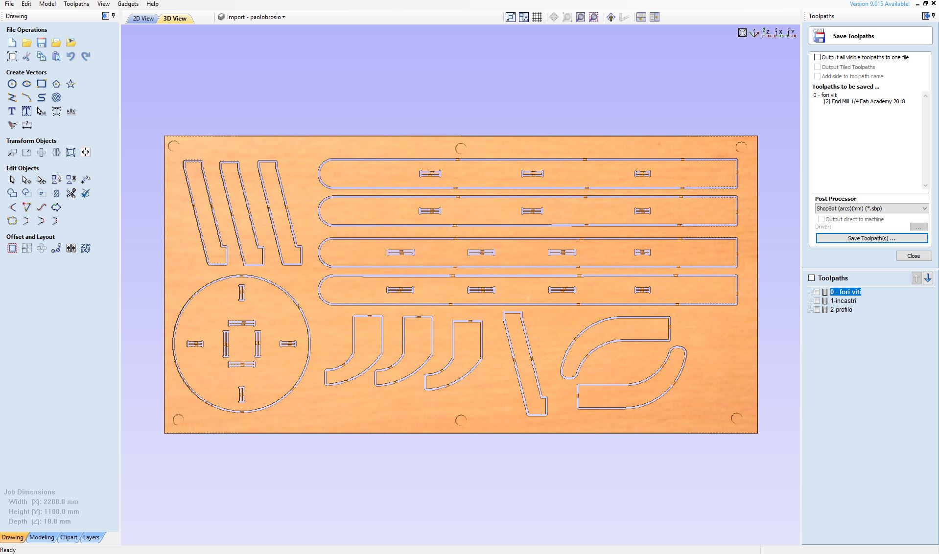
Once I finished my AI vector file, I opened it in Vectric Aspire, in a new document with dimensions 2000 x 1100 x 180 mm. I decided to create 3 files: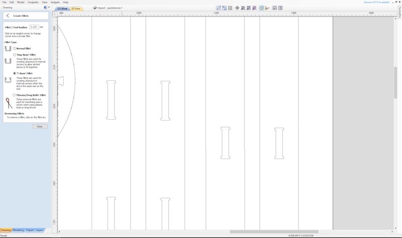
Here I set also parameter for the tip.
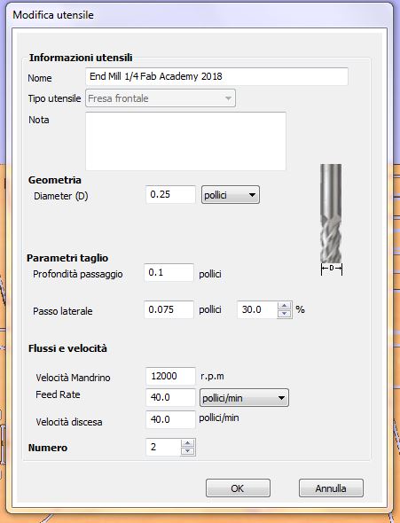
About Feedrate I choosed 40 inch/min using the formula:
Feedrate = RPM * n° of cutting edges * chiploadI also set 7 passes, so every passes will cut around 2.5 mm of material.
where:
- RPM = 12000 (choosed looking previous years documentations)
- n° of cutting edges = 2 (choosed looking my tip)
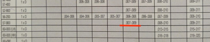
- chipload = 0.007 (choosed looking tip's manufacturer documentation about soft wood cutting and relative to my 1/4'' 57/900 tip)
The result is Feedrate = 12000 * 2 * 0.007 --> 168 inch/min. I choosed 40 because is my first cut and I want to go slow in order to prevent any kind of problem.
SHOPBOT SETUP
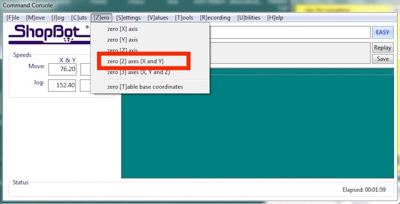
The ShopBot is a sort of large version of the Roland milling machine that I used in these weeks: it's simple much more dangerous! But basically it needs same procedures to works, first of all setting X, Y and Z axis. X and Y could be set in[Z]ero - zero [2] axes (X and Y)
and Z in
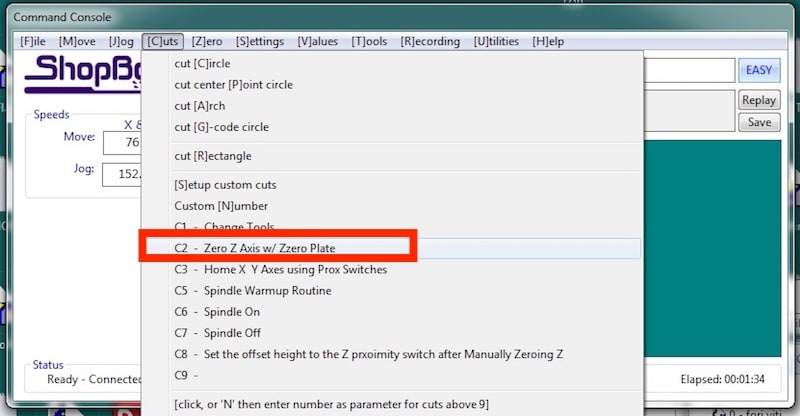
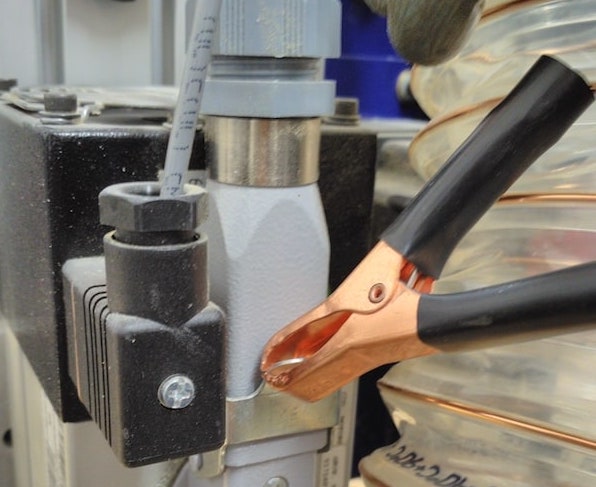
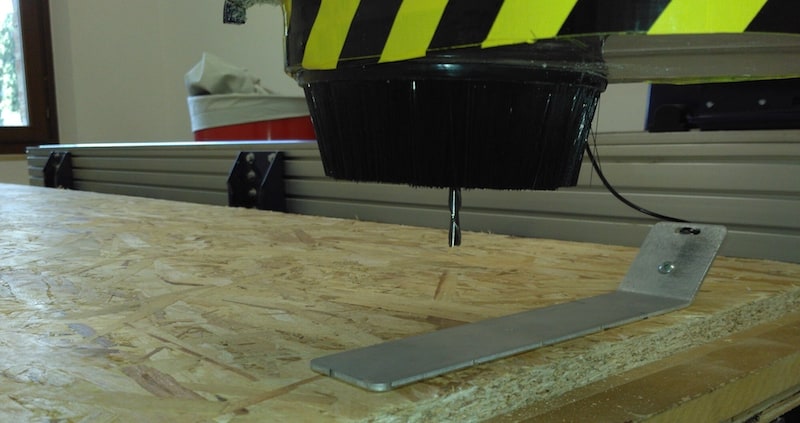
[C]uts - C2 Zero Z axis w/Zzero Plate using the metal plate that helps to calibrate automatically the Z axis of the ShopBot.
My workflow included cleaning the sacrificial table and paying attention to every minimum passage, always having me supervised by Simone and by one of my classmates (this time, Antonio).
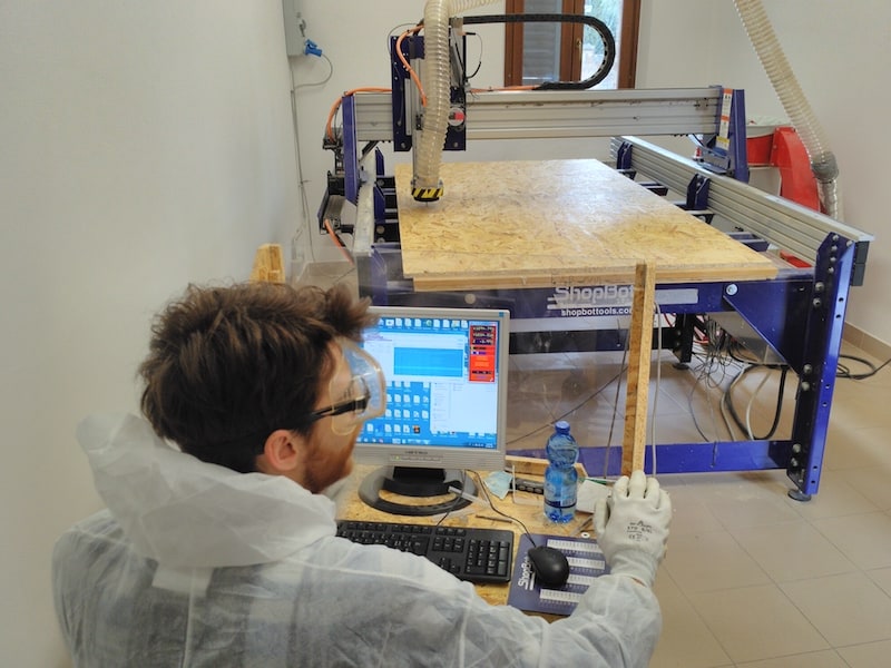
THE CUT
And finally the cut. I spent around 5 hours and half in front of ShopBot machine looking at every movements, always with the STOP button near my hand.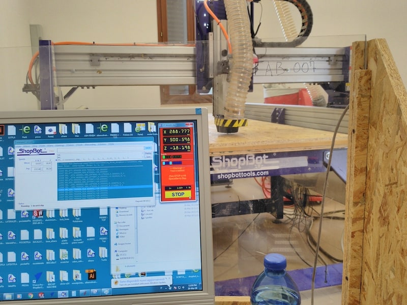
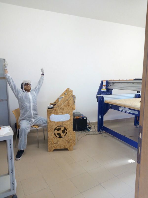
Here my reaction after this long day.
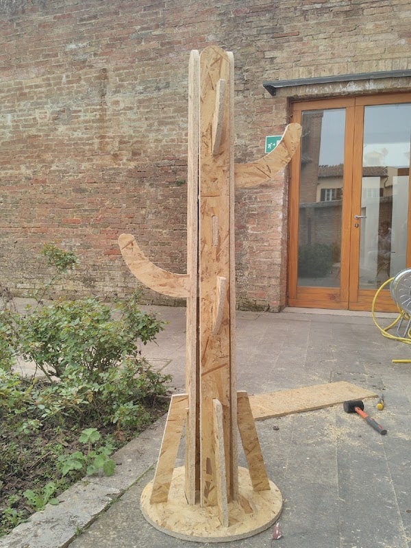
And finally my work finished:
--> Download week7.zip (ZIP Archive, 2.4 MB)