WEEK 10: INPUT DEVICES
Objectives
Group assignment:Have I...?
DESIGN MY BOARD
For this weekly assignment I decided to create something that could be useful for my Final Project, a kind of starting point: a board with an input sensor to read water flow. Infact the sensor I decided to use is the G1/2'' Water Flow Sensor Enclosure, model YF-S201C. It has an internal fan that rotates when liquid passes inside. It has also 3 wires: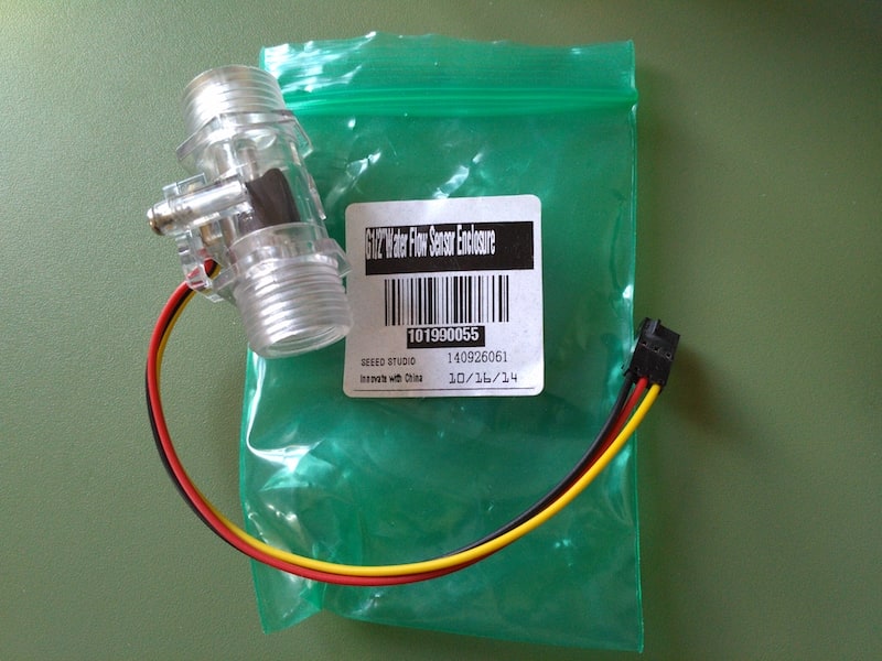
So my idea was to start creating a simple board that could only read this kind on input data and nothing else.
Looking also to Neil's sample boards (Link), I decided to use an ATtiny45 as microcontroller. So, first of all I opened one of Neil's board (in particular, the motion board) and the ATtiny45 datasheet in order to comprehend why and how insert components on my board.
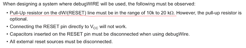
So I looked for the 10kΩ resistor and the 1uF capacitor. Inside the datasheet I found that:
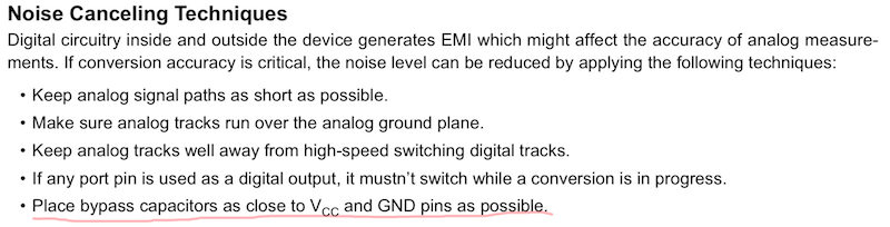
So I Googled "decoupling capacitor" and I've found This Sparkfun webpage: it says that:
To follow good engineering practice, always add at least one decoupling capacitor to every IC. Usually 0.1µF is a good choice, or even add some 1µF or 10µF capsSearching for bypass capacitor calculator on Google I found a good Calculator and put values for frequency clock and resistor, I could find the minimum values for the capacitor for my circuit. But now I understood why Neil used 1uF capacitor in his board.

So I understood that I optionally can use a 10kΩ pull-up resistor in my board.
As last thing of my little research, I searched about Rx and Tx for serial communication. In Neil's board, he connect Rx of the FTDI to SCK pin of the microcontroller. The SCK pin (for ATtiny45 is the PB2) is dedicated to serial clock input, but why Rx? The answer is:
A serial bus consists of just two wires - one for sending data and another for receiving. As such, serial devices should have two serial pins: the receiver, RX, and the transmitter, TX. (source)

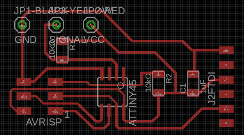

In this schematic there are two 10k pull-up resistors. In a second time I desoldered the R2 pull-up (from sensor input to VCC) because it may have been one of the reasons why I could not program correctly. I have corrected this also in the Eagle project (the images and the download of the correct file are at the end of the page).
TEST COMPONENTS
Before write the program to read data from my board I decided to test the water flow sensor, first of all to be sure that it works. Think I used for this test was: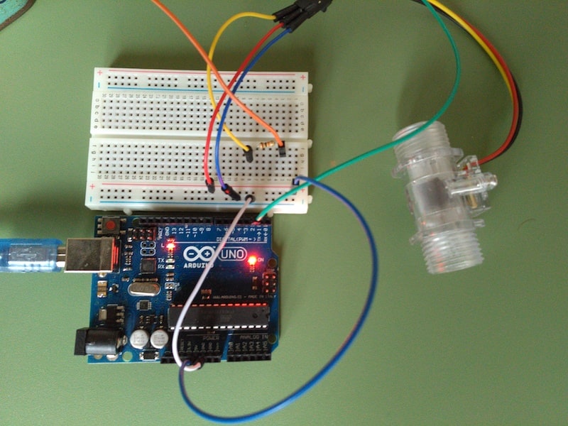
// reading liquid flow rate using Seeeduino and Water Flow Sensor from Seeedstudio.com
// Code adapted by Charles Gantt from PC Fan RPM code written by Crenn @thebestcasescenario.com
// http:/themakersworkbench.com http://thebestcasescenario.com http://seeedstudio.com

volatile int NbTopsFan; //measuring the rising edges of the signal
int Calc;
int hallsensor = 2;    //The pin location of the sensor

void rpm()     //This is the function that the interupt calls
{
  NbTopsFan++;  //This function measures the rising and falling edge of the hall effect sensors signal
}

void setup() //
{
  pinMode(hallsensor, INPUT); //initializes digital pin 2 as an input
  Serial.begin(9600); //This is the setup function where the serial port is initialised,
  attachInterrupt(0, rpm, RISING); //and the interrupt is attached
}

void loop()
{
  NbTopsFan = 0;   //Set NbTops to 0 ready for calculations
  sei();      //Enables interrupts
  delay(1000);   //Wait 1 second
  cli();      //Disable interrupts
  Calc = (NbTopsFan * 60 / 7.5); //(Pulse frequency x 60) / 7.5Q, = flow rate in L/hour
  Serial.print(Calc, DEC); //Prints the number calculated above
  Serial.print(" L/hour\r\n"); //Prints "L/hour" and returns a new line
}
As you can see the sensor works properly, so I was ready to proceed with my own components.
PROGRAM MY BOARD
I am not a technical computer language specialist, so probably I'll say some nonsense or imprecision in my explaination
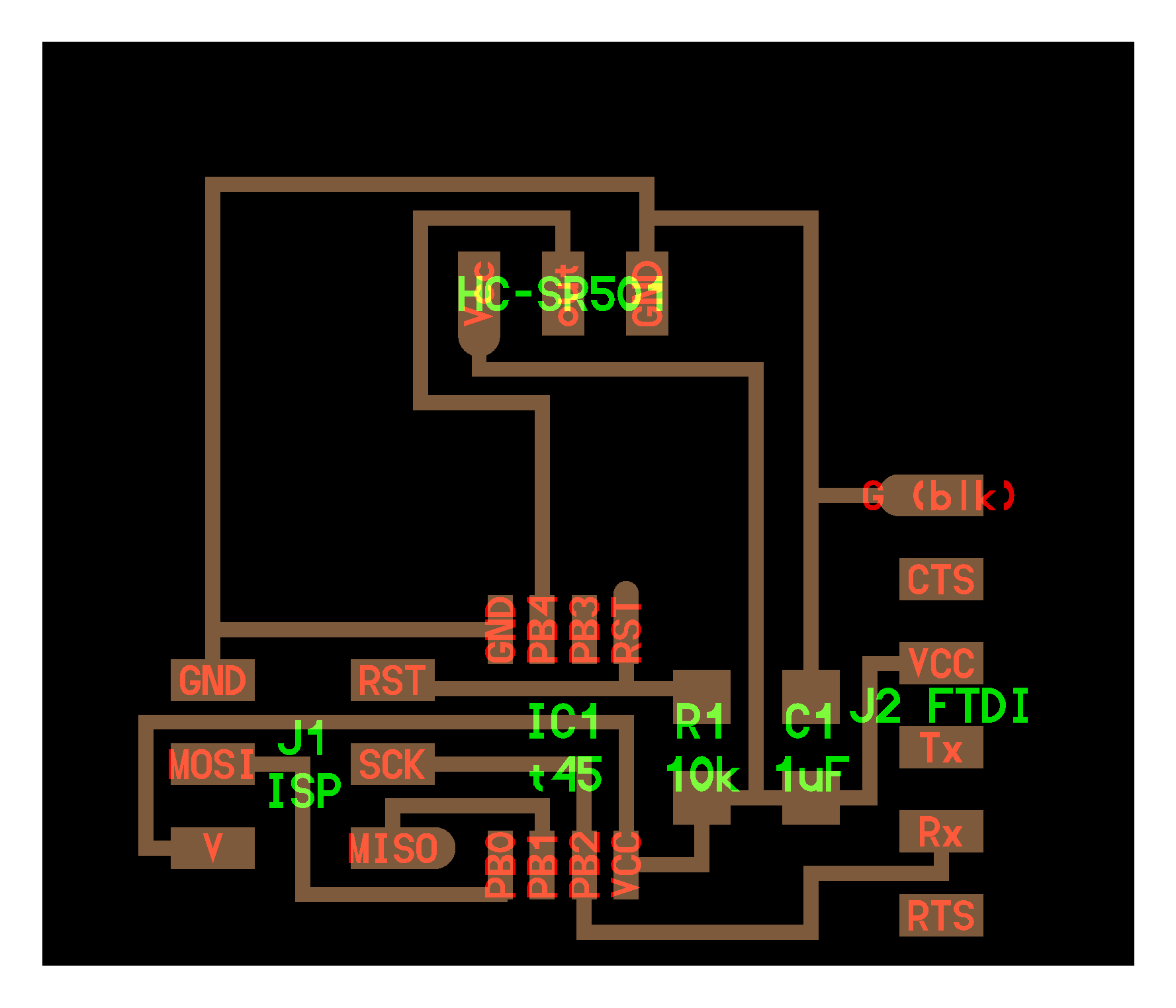
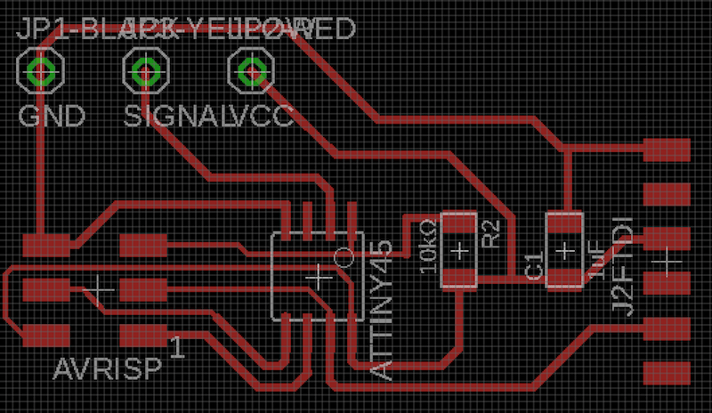
As you can see in the screenshot of my schematic in Eagle, I design my board for recive signal from my water flow sensor to pin PB3, that is the Arduino pin n° 3.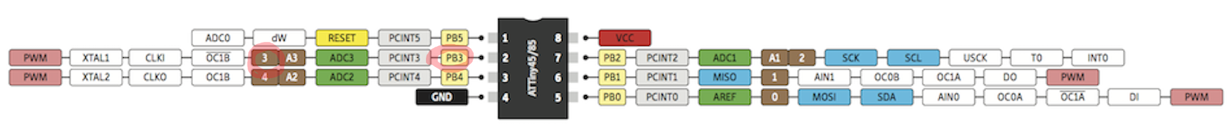
Before starting, I include the library
SoftwareSerial.h in order to allow serial communication in the ATtiny 45, so I uploaded this simple code:
#include <SoftwareSerial.h>
#define rxPin 2
SoftwareSerial serial(10, rxPin);
int analogPin = 3;

int val = 0;

void setup()
{
  serial.begin(9600);              //  setup serial
}

void loop()
{
  val = analogRead(analogPin);     // read the input pin
  serial.println(val);             // debug value
}
and actually my board could read values (something) from the water flow sensor.

Than i tried to modify both codes I've found online so that they could work on my board.
#include <SoftwareSerial.h>
#define rxPin 2
#define flowPin 3

SoftwareSerial serial(10, rxPin); //the first pin (10) it's fake
volatile int NbTopsFan;
int Calc;
int hallsensor = flowPin;

void flow()
{
  NbTopsFan++;
}

void setup() //
{
  pinMode(hallsensor, INPUT);
  serial.begin(9600);
  attachInterrupt(0, flow, RISING);
}

void loop()
{
  NbTopsFan = 0;
  sei();
  delay(1000);
  cli();
  Calc = (NbTopsFan * 60 / 7); //Flow rate (L/h) = Pulse frequency * 60 / 7Q, where 7Q comes from datasheet
  serial.print(" L/hour\r\n");
}
But also after some try my PC didn't read properly the code. It printed a list of stationary values (1 or 8 L/hours) in my serial monitor. Than starts the "debug period", been helped by my mate Simone, in order to understand why my board didn't trigger correctly the interrupt function.
First of all, why use the function interrupt? And second, what is an interrupt?.
An interrupt (that could be external, internal or software), is a signal to the processor that says to it "look, stops any function you're doing and execute that signal." (Interrupt - Wikipedia). In my case, I understood that codes found online use an interrupt to avoid time problems, since the input signal was a flow. In Arduino, the function used to trigger an interrupt is
attachInterrupt. In examples I found, the lexicon use is something similar to this: attachInterrupt(0, ISR, RISING);. It does it means that it will trigger an interrupt to pin INT0, for a varialble (must defined as volatile) with the RISING mode (that trigger the interrupr when the pin goes from low to high) (source).
So I understood that the interrupt function is probably necessary to have data I want to read.
But why I see a stationay value and my function
NbTopsFan++ doesn't grow?
There could be two hypothesis:
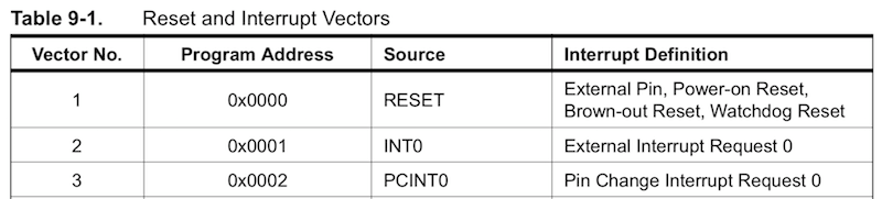
Than the solution is to use PCINT instead of INT?
Maybe, but also Googling I didn't found any Arduino lexicon to make it. But I found something useful, a tutorial that explained me how to manage PCINT on ATtiny85 (Link). In a couple lines it explain how to focus attention for PCINT instead of INT using C code, deleting the need of the attachInterrupt function. Referring to Paragraph 9.3.2, p.50 and Paragraph 9.3.4, p.51 of the datasheet, using GIMSK – General Interrupt Mask Register and PCMSK – Pin Change Mask Register (the register control which pins contribute to the pin change interrupts, datasheet Paragraph 9.2, p.48), it managed to enable pin change interrupt and turn on pin interrupt to a specific PORTB pin (in my case I wanted to set it to PB3, the port connected to the sensor). Than I modified the code deleting attachInterrupt and inserting these C code, but unfortunately Arduino didn't compile it giving an error with this new code and SoftwareSerial.
Why?
Googling the error, I found this page of the Arduino forum. Here I found my same problem and I understood that there would be some conflicts between SerialSoftware library and the new code I wrote. The user nickgammon suggest an alternative library (modified by his own called SendOnlySoftwareSerial, Link GitHub; instruction to install it are inside the GitHub page) that only allows to sending data and not receiving it. And it's bsaically what I need. Infact, as my board is designed, the PB2 is shared in INT0 (for interrupt) and RX (for serial). This double functionality I set in my previous code using attachInterrupt caused a sort of wrong lecture, which translated into showing a static value (my NbTopsFan++; didn't grow) whether I was blowing inside the sensor or not.
So finally, here's the correct final code.
#include <SendOnlySoftwareSerial.h>
#define rxPin 2
#define flowPin 3

SendOnlySoftwareSerial daS(rxPin); //"daS" means darioSerial
volatile int NbTopsFan;
int calc;
int sensor = 3;    //the pin connected to the sensor

void setup() //
{
  pinMode(sensor, INPUT); //initializes digital pin 2 as an input
  GIMSK = 0b00100000;    // turns on pin change interrupts
  PCMSK = 0b00001000;    // turn on interrupts on pins PB3
  daS.begin(9600);
}

void loop()
{
  NbTopsFan = 0;   //Set NbTops to 0 ready for calculations
  sei();      //Enables interrupts
  delay(1000);   //Wait 1 second
  cli();      //Disable interrupts
  calc = (NbTopsFan * 60 / 7.5); //(Pulse frequency x 60) / 7.5Q, = flow rate in L/hour
  daS.print(calc, DEC); //Prints the number calculated above
  daS.print(" L/hour\r\n"); //Prints "L/hour" and returns a new line
}

ISR(PCINT0_vect)
{
  NbTopsFan++;  // Increment volatile variable
}
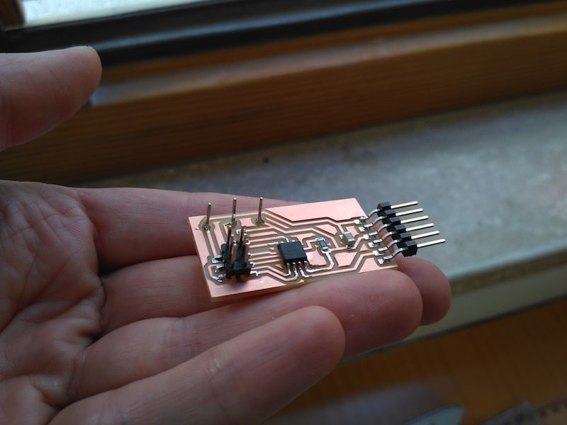
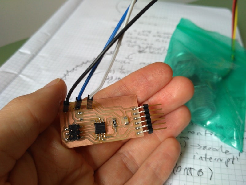
In this case Arduino IDE compile it properly and I could flash it in my board using the programmar I made during Week 4.
TEST MY BOARD
The test...well...this week makes me completely mad...expecially last two days. I have had to deal with a lot of information and problems at the same time that I have probably only partially understood and that will need further investigation. But finally and fortunately everything seems to work properly.| Component | Value | Description | Eagle library |
| JP1/JP2/JP3 | - | pin header | pinhead |
| R1 | 10kΩ | resistor | fab library |
| C1 | 1uF | capacitor | fab library |
| ATtiny45 | - | microcontroller | fab library |
| AVRISP | - | ISP | fab library |
| J2 FTDI | - | FTDI | fab library |
--> Download week10_water_board.zip (ZIP Archive, 111 KB)