WEEK 13: NETWORKING AND COMMUNICATIONS
Objectives
Group assignment:Have I...?
I2C Communication
As first weekly work I decided to try the I2C Communication.The Inter-integrated Circuit (I2C) Protocol is a protocol intended to allow multiple “slave” digital integrated circuits (“chips”) to communicate with one or more “master” chips. Like the Serial Peripheral Interface (SPI), it is only intended for short distance communications within a single device. Like Asynchronous Serial Interfaces (such as RS-232 or UARTs), it only requires two signal wires to exchange information. Via
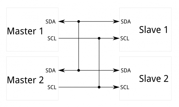
In I2C communication it's possible to create a communication between at least two components, a master and a slave. As requested by the assignment, I used two of mine board: the board I made for Input Devices (with an ATtiny45) and the board I made for Electronics Design (with an ATtiny44). I decided to make the ATtiny44 one the master reader board and the ATtiny45 one the slave sender one. It needs basically two communication channels:
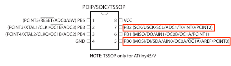
ATtiny45 - DATASHEET
ATtiny44 - DATASHEET
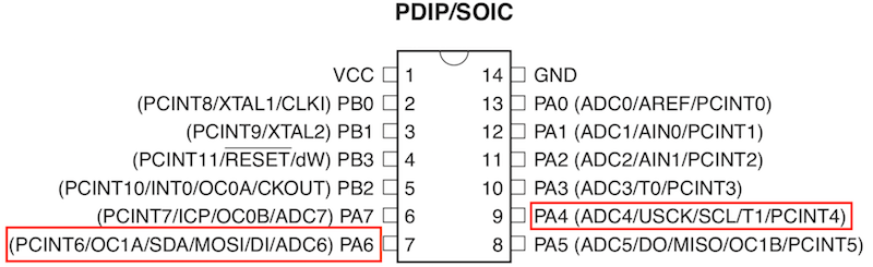
So I had to connect, using ISP pins:
MASTER CODE
My Master has ATtiny 44 with an external 20MHz clock. Here I used TinyWireM library, modified for working with "Tiny" microcontrollers and included in Arduino IDE. Here is its official GitHub page.
/* --MASTER CODE -- */

#include <SoftwareSerial.h>
#include <TinyWireM.h>
#include <USI_TWI_Master.h>

SoftwareSerial darioSerial(0,1);

void setup(){
  darioSerial.begin(9600);
  TinyWireM.begin();
  delay (300);
}

void loop(){
  darioSerial.println("Hey I want to communicate");
  TinyWireM.requestFrom(8,1);
  while (TinyWireM.available()) {
    int m = TinyWireM.receive(); //m is for "message"
    darioSerial.println(m);
}
  delay (600);
  }
SLAVE CODE
My slave has an ATtiny45 with internal 8MHz clock. For slave code I used TinyWireS, as suggested by This tutorial. This library isn't included in Arduino IDE by default, so I had to add it downloading by its GitHub Page.
/* --SLAVE CODE-- */

#include <TinyWireS.h>

void setup(){
  TinyWireS.begin(8); // join I2C bus with address #8
  TinyWireS.onRequest(test);
}

void loop(){
  TinyWireS_stop_check();
}

void test(){
  TinyWireS.send(0);
}
Results
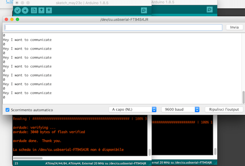
I flashed codes to my boards, I connected 4 pins as I explained before and I connected the master to my PC using an FTDI cable. I expected that my master send "Hey I want to communicate" and the slave "0". And infact this is the result: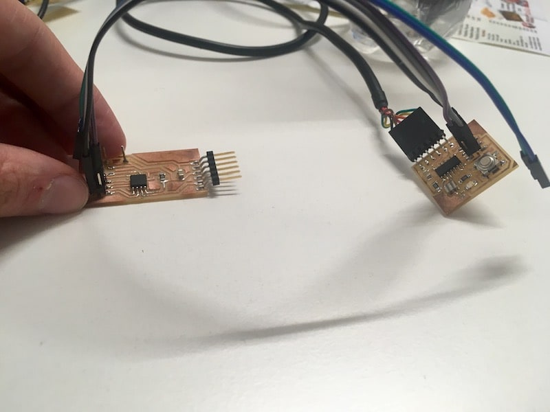
Bluetooth Communication
I also tried to use a Bluetooth module to send wireless data to my laptop. That could be useful for my Final Project. As first thing, I tried to configure my HC-05 Bluetooth module for being seen by my laptop or smartphone, in order to understand better the right process to set it as well. I followed This useful tutorial, that helped me to enter in AT Command Mode and send command and settings via serial port using an Arduino Uno board.According with the tutorial linked before, I upload the following sketch in a Arduino Uno board:
#include <SoftwareSerial.h>

SoftwareSerial BTSerial(10, 11); // CONNECT BT RX PIN TO ARDUINO 11 PIN | CONNECT BT TX PIN TO ARDUINO 10 PIN

void setup()
{
  pinMode(9, OUTPUT);  // this pin will pull the HC-05 pin 34 (key pin) HIGH to switch module to AT mode
  digitalWrite(9, HIGH);
  Serial.begin(9600);
  Serial.println("Enter AT commands:");
  BTSerial.begin(38400);  // HC-05 default speed in AT command
}

void loop()
{

  // Keep reading from HC-05 and send to Arduino Serial Monitor
  if (BTSerial.available())
    Serial.write(BTSerial.read());

  // Keep reading from Arduino Serial Monitor and send to HC-05
  if (Serial.available())
    BTSerial.write(Serial.read());
}
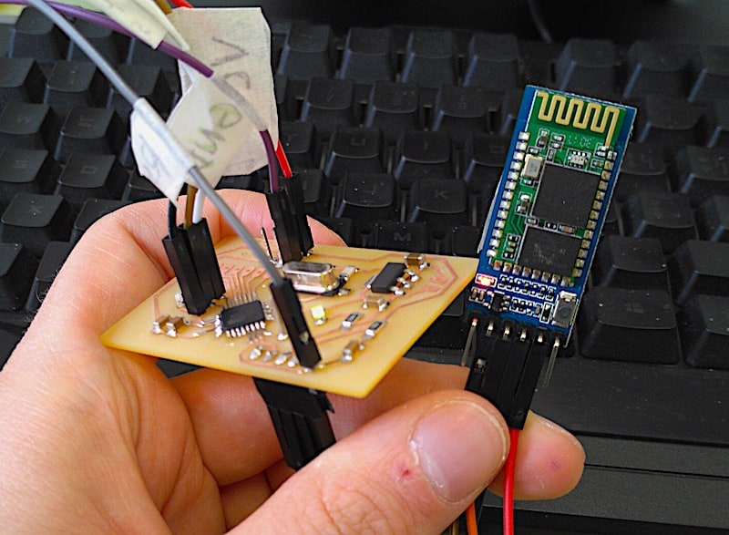
And connected the BT module to the board using this wiring layout:
The complete list of AT commands is available HEREAfter seeing again the tutorial, I understood that for entering in AT Command Mode, I had to press the little button on the bluetooth module and than connect the Arduino to my laptop. The feedback I had to receive was a 2-second delay of the red LED on the module. You can see the different delay between normal communication mode and AT command mode.
Than I opened again the serial monitor and, after verifying the right connection typing
AT and receiving OK as answer, I setted the module with these parameters:
AT+NAME=Water0AT+PSWD=1234AT+UART=38400,1,2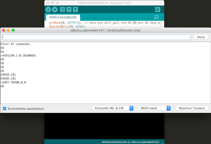
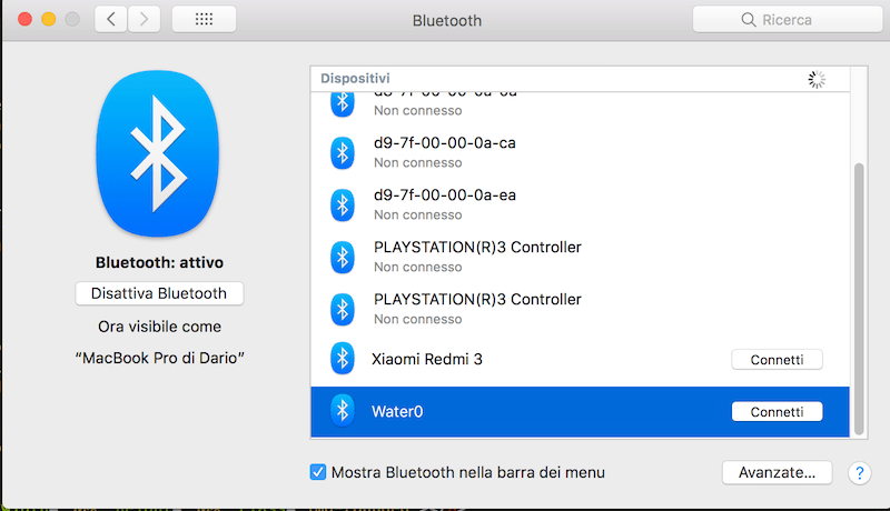
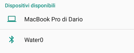
So I disconnected e re-connected the Arduino for switching to normal communication mode in order to verify if the module would be properly recognized by my laptop and my smartphone. And this is the result:
So I tried to change the code. I made one that could read data coming the water flow connected to pin 2 and print in serial monitor via bluetooth. As you can see, in this passage I used my own board instead of Arduino Uno. I have described the board used in the following paragraph. The code I used is:
volatile int NbTopsFan;
int calc;
int sensor = 2; // pin connected to the sensor
void rpm()
{
NbTopsFan++;
}
void setup() {
pinMode(sensor, INPUT);
Serial.begin(38400);
attachInterrupt(0, rpm, RISING);
}
void loop() {
NbTopsFan = 0; //Set NbTops to 0 ready for calculations
sei(); //Enables interrupts
delay(1000);
cli(); //disable interrupts
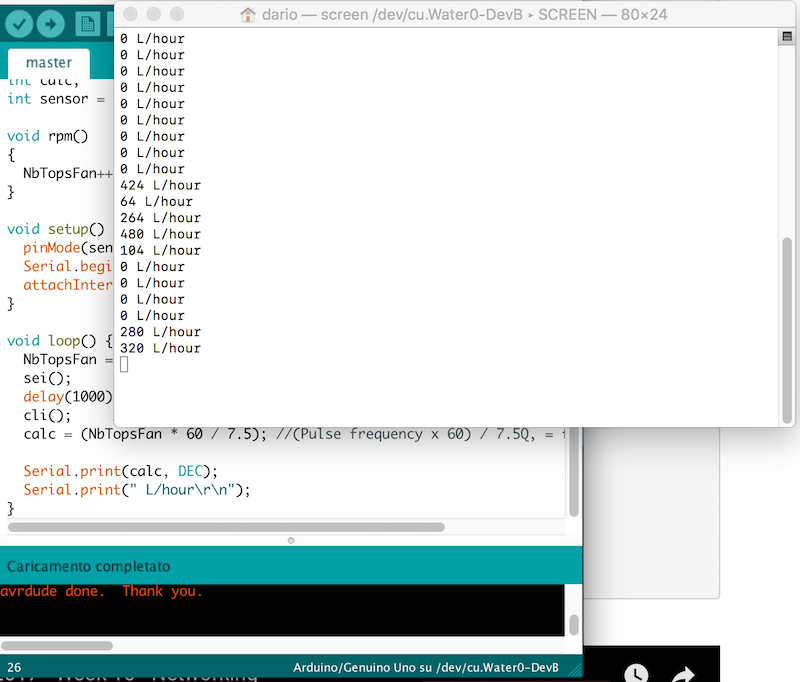
calc = (NbTopsFan * 60 / 7.5); //(Pulse frequency x 60) / 7.5Q, = flow rate in L/hour
Serial.print(calc, DEC);
Serial.print(" L/hour\r\n");
}
I obviusly connected Bluetooth's RX to Arduino's TX and vice versa. I also connected water flow sensor to GND, VCC and pin 2. So I connected my laptop to bluetooth module Water0 with 1234 as password, I launched the Terminal app and I wrote
screen /dev/cu.Water0-DevB to open a serial communication via this serial port (the bluetooth one) and this is the result:
And here a video to show the good result I obtained:
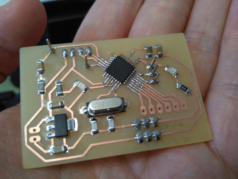
Board
As I said before, I designed a new board to be used also for Previous Week. I have also thought of it to be used for my Final Project, inserting a voltage regulator to reduce the current from 12 to 5V, a predisposition for external power supply and, of course, 4 pins for bluetooth communication (TX, RX, VCC and GND).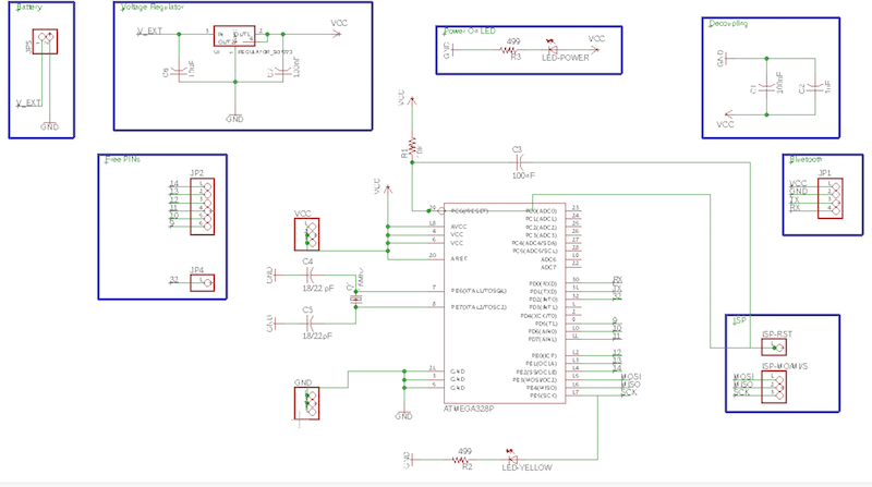
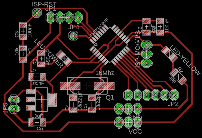
BOM
| Component | Value | Description | Eagle library |
| R1 | 10kΩ | resistor | fab library |
| R2/R3 | 499Ω | resistor | fab library |
| R3 | 499kΩ | resistor | fab library |
| C1/C3/C7 | 100nF | capacitor | fab library |
| C2 | 1uF | capacitor | fab library |
| C4/C5 | 18/22 pF | capacitor | fab library |
| C6 | 10uF | capacitor | fab library |
| ATmega328P | microcontroller | fab library(ATMEGA88-THIN package) | |
| Crystal | 16 Mhz | CSM-7X-DU | crystal |
| Regulator | - | SOT223 | fab library |
| LED | - | led | fab library |
| headers | - | pinhead |
--> Download week13_board.zip (ZIP Archive, 107 KB)