Final Project
Project Development schedule is available here!
General description
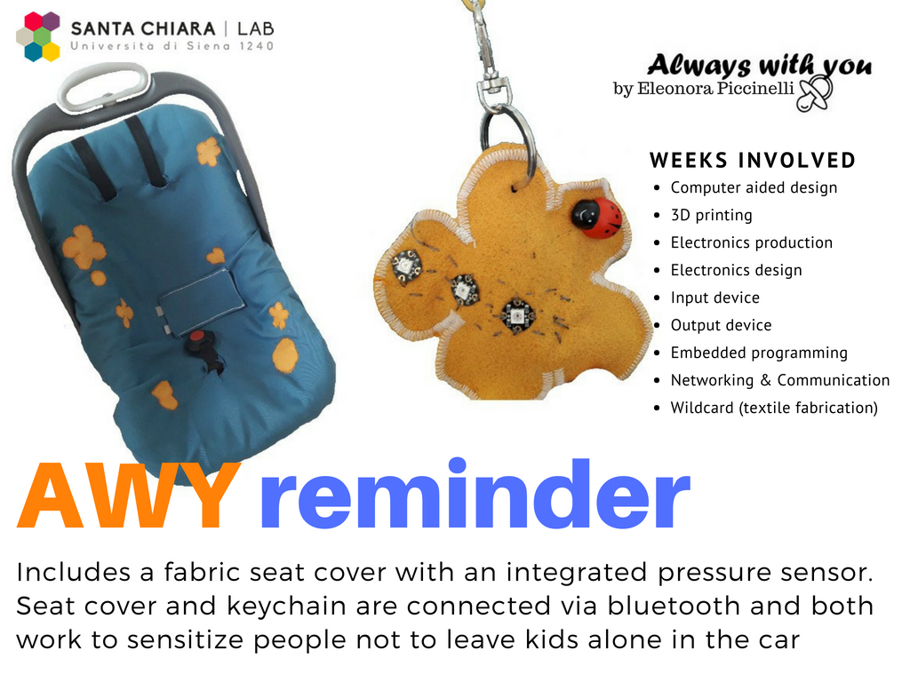
I will collaborate with Assist Digital and as agreement I'm going to deal with the Automotive sector. I'm really focused on the topic of the road safety. Particularly, I'm really interested in avoiding child abandon inside cars. Thanks to integrated Bluetooth options I would like to connect two devices. The first one will be represented by a sensor that measures the baby presence on the child seat. The other device will be a keychain for your car's key. In this way, the electronics parts would be able to connect the devices I've in mind and send a warning signal. To be more exact, if the first device notices your baby is still on the child seat but your keys are too far from him, the keychain will represent an output with a sound signal and it will work as a reminder.
After having had this "idea" for my final project, I obviously googled some information on the Internet. I read about some similar project done during the previous years and I found them very interesting. In most cases people has used cables physically connected from the cigar lighter socket to the child seat. In addition, there are more technological cases based on a webapp available on you car screen, but until now, parents are obliged to set the lenght of travel in order to receive a sound signal at the end of it. I found it a bit intricate. Most people don't want to "waste time" in setting too many information on GPS navigation device and or placing pyhisical cables in order to connect the car and the child seat. I think the current lifestyle is related to be always in a rush and...it could be useful having a reminder to recall the importance of some things to your mind...especially when it comes to your child!
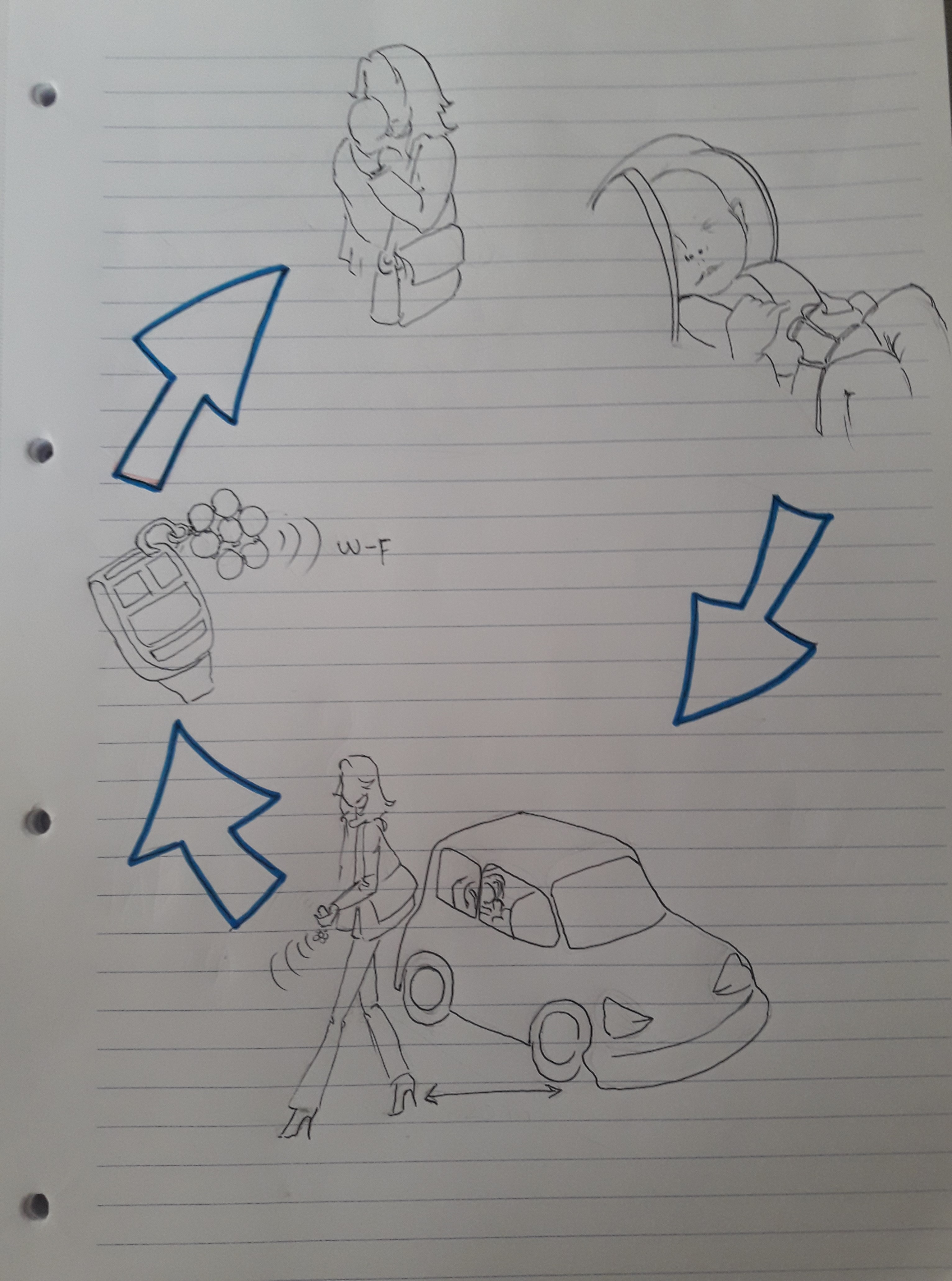
Here, there's a simple sketch I drew on paper.
Weeks involved
In order to sew a seat cover for the child seat, I'm going to use some fabric pieces and the velostat. Obviously, the master board (writer) linked to the Bluetooth connection, will be integrated within it. Then, I'd like print a keychain with a pacifier shape and I'll put the slave (reader) board on it. It will be parents' reminder (thanks to a sound signal). Considering these main information, you can find an useful list below (related to the Fab Academy's weeks).
What I need to create my final prototype?
Computer-aided design: useful to create a logo using 2D design and modeling the keychain on 3D software
Vynil cutter: in order to print the final logo
3D printing: useful to recreate a part of the keychain in a real shape
Electronics production, Electronic design, input/output device, networking & communication: weeks that allows me to develop my devices
Wildcard: useful to learn sewing and working with the textile's world and its wearable technologies
Useful links:
Velostat - Wearable technologiesConductive material
Come to a decision! - Child safety film
Child safety bracelet
Remmy - Car baby alert (Italian webpage)
How to get what you want! (Wearable Technology Documentation)
Guidelines to fabric sensors
How to make a pressure sensor - YouTube tutorial
Handcrafting textile sensor
Update 18th May 2018:
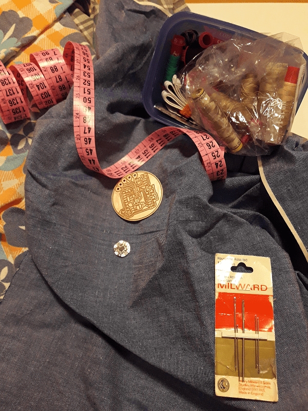
After the challenging two weeks related to the Machine building, I finally start to manage my time in order to work on my final project. The wilcard week has been extremely important to try the textile fabrication. Before starting, I looked for some information on the Internet and I also spoke with my instructor to have some suggestions. He gave me the Lilypad main board, an accelerometer and a power cable. Now it's time to be creative! :D After an energic cup of coffee, I googled many and many information on a great quantity of websites. I had an infinite number of open windows on my laptop (music included!) I tried looking for some fabrics pieces inside my lab and I found many pieces of them! Great, isn't it? In the next days, I'll finally use get a child seat on loan. In the meanwhile, during my work's lunch break on Saturday, I found a bit of time to find other fabric pieces inside my house too and I gave a great news to my mother: "Mum! You must teach me sewing!!" So, she explained me the basic tecniques in order to work correctly. (See more on the wildcard week)
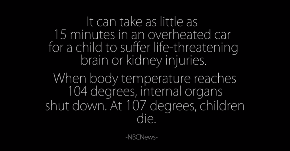
During the same afternoon and the following days, many Italian newspaper wrote about an event that shocked me so much and it was linked to my final project. There has been an other child's death inside a car. Considering this terrible event, I'm very motivated in order to create a final project in this field. I'm aware of its uncomplexity because the Bluetooth module has a limited radius of action, and even if I'll realize a small part for the Fab Academy experience, I'm really focused on its importance and I'd like to improve the project in the near future. Many similar project has been done in Italy but it doesn't exist a law related to that. I hope that my project, will be take into consideration to be implemented in the best way as possible. It has been a long work in order to create something complete and without any kind of lacks. Anyway, I'm really happy to prototype something that interested me so much and could be useful for the whole society. I've been breathing down my neck and I'm really focused on planning my schedule for the next two weeks (OMG!). So, after having sewed the final outline of my child seat, I would like to spend my time in trying Bluetooth connection module and connect the master and the slave to my main boards. Then, I'll work on the 3D software in order to create the car's keychain and I'll do some tests related to the proportioned dimensions. Most challenging part? Writing the master and the slave's codes! Anyway, I'm really motivating in order to work hard!
Update 24th May 2018:
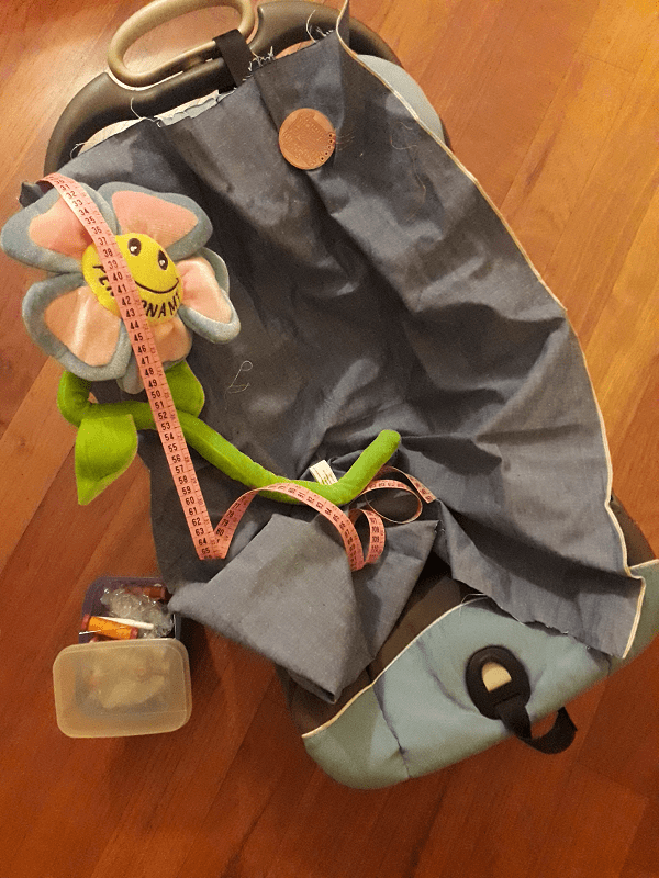
Today, a friend of mine borrowed me her baby's child seat. Even if I already had in mind the estimated dimensions, now I can define them in a more precise way. So, during the next days, I would like to complete the whole child seat cover. I really like the piece of fabric on which I did the quick sew test (see the wildcard week) and I'm going to continue working on it. In the meanwhile, I also thought about the shape I'd like to recreate for the sensor's upholstery.
Update 27th May 2018:
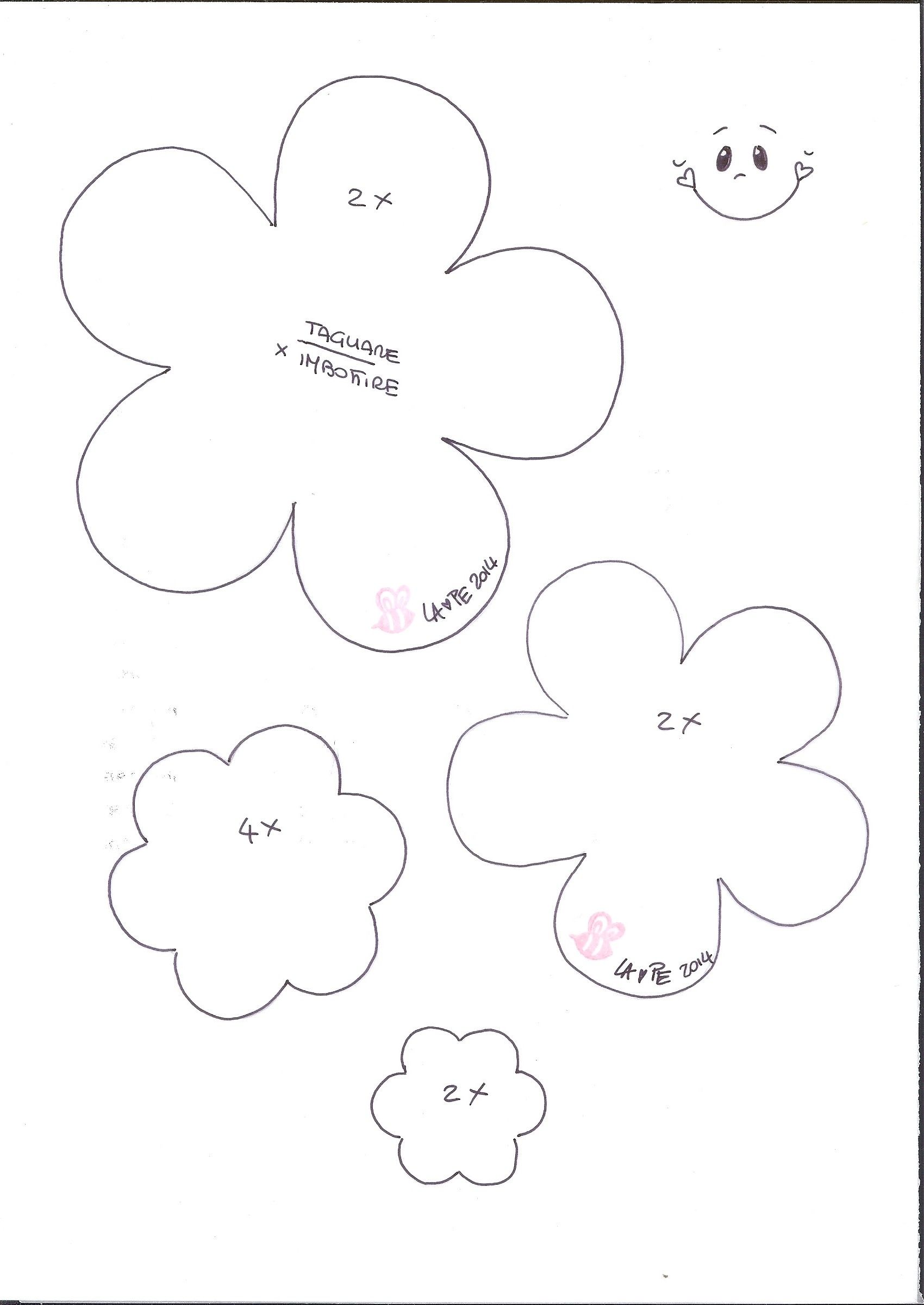
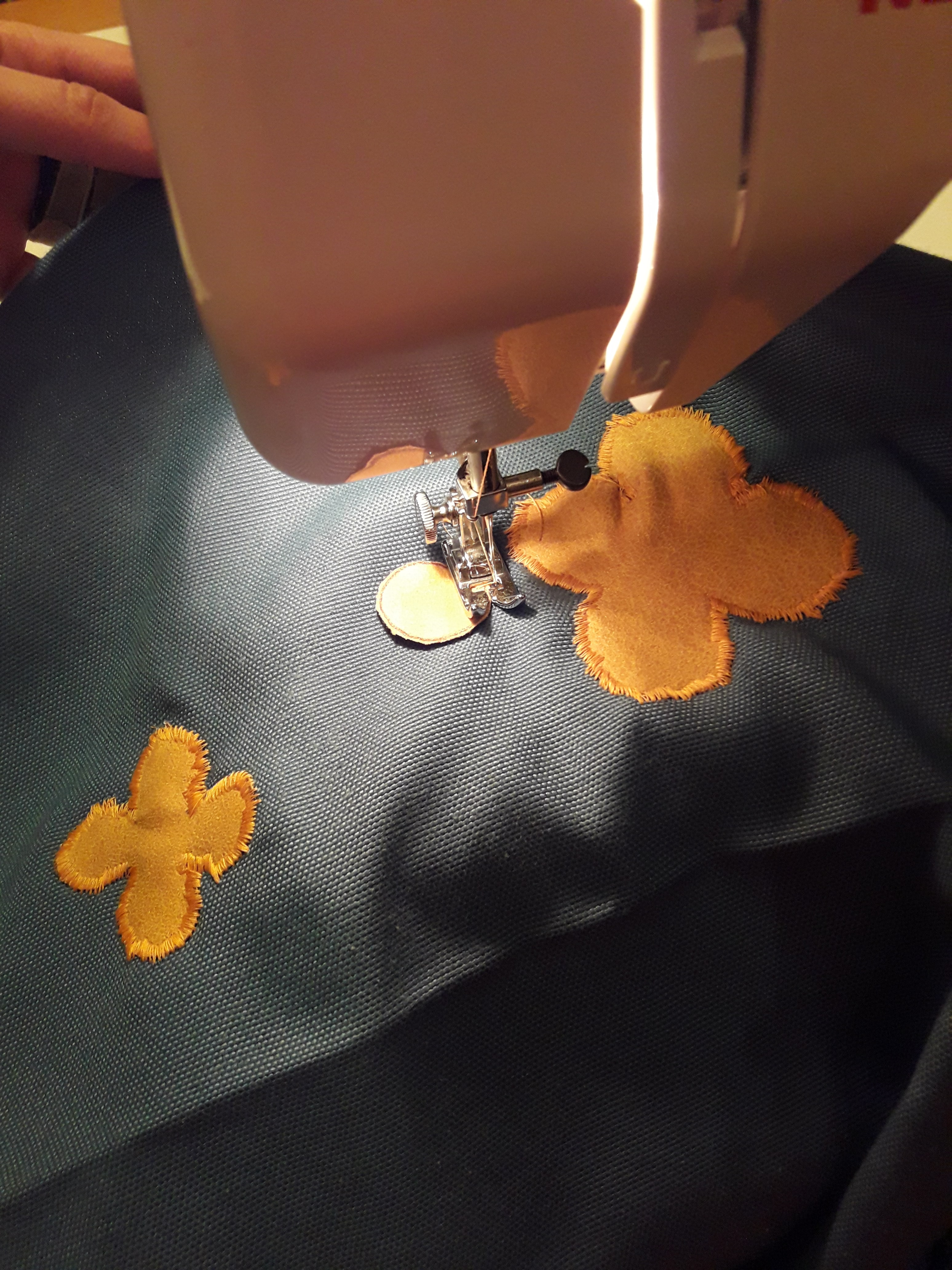
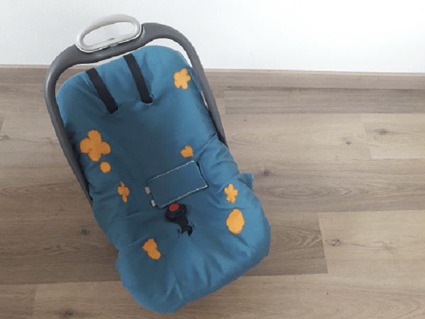
Today, Iìve finished the child seat cover. I sketched dimensions thanks to a real child seat shape and I worked in order to sew it properly and fix the yellow shapes on it. Here, I'm going to make a list of what I did:
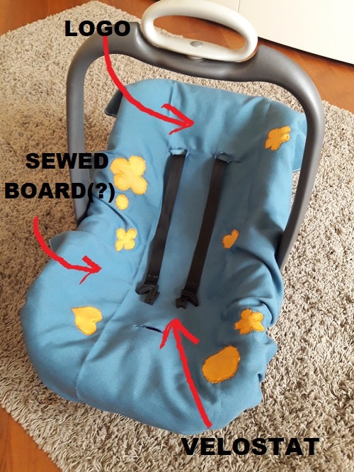
Until now, I've finished the child seat cover and I've just in mind where to put the missing elements! At the moment, I would like to do a quick test with a small piece of velostat. It will be helpful in order to understand the value of needed resistor. Doing so, when I'll mill and solder my board, I'll be sure of its value. Morover, thanks to a sample of velostat, I defined its dimension considering the child seat as the main object. In addition, I looked for the woven conductive fabric and thir properties can be sum up in the following lines:
Woven conductive fabric
Pros
Cons
More that this, I also drawn a pacifier shape on Fusion 360 and I did a final logo on InkScape. The latter one includes a simple black written with the name I've in mind for the project: "Always with you". Maybe it could be overly sentimental or sickly sweet (or whatever you want to call it), but I liked it because I immediately thought about a pacifier shape linked to the Y of "you" as a symbol of emotional bond. In other words, the name can have two language functionalities. It reminds to two unforgettable elements: your baby and the usefulness of a perfect match: cover seat and alert keychain! Yes, I know my semantic and phylosophical way came out and let me say sorry for that...you can understand I studied things like marketing and cognitive psychology. Enough chitchat, let's get straight to the point!
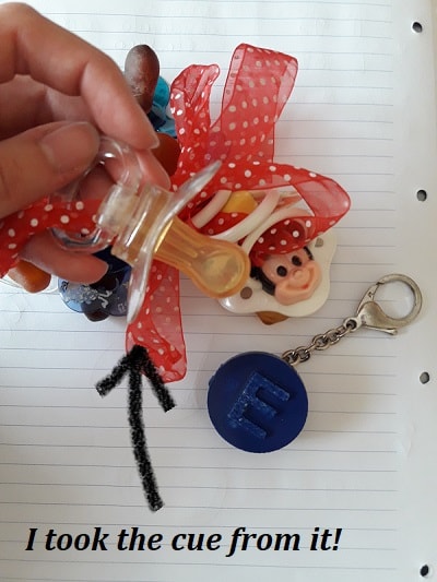
Here you can find the steps I followed to draw a pacifier shape on 3D CAD. Considering the fact I knew there were different shapes, I decided to better looking for them inside my house and I magically found my pacifiers! What more could you ask for? There were a perfect starting point to be taken into consideration.
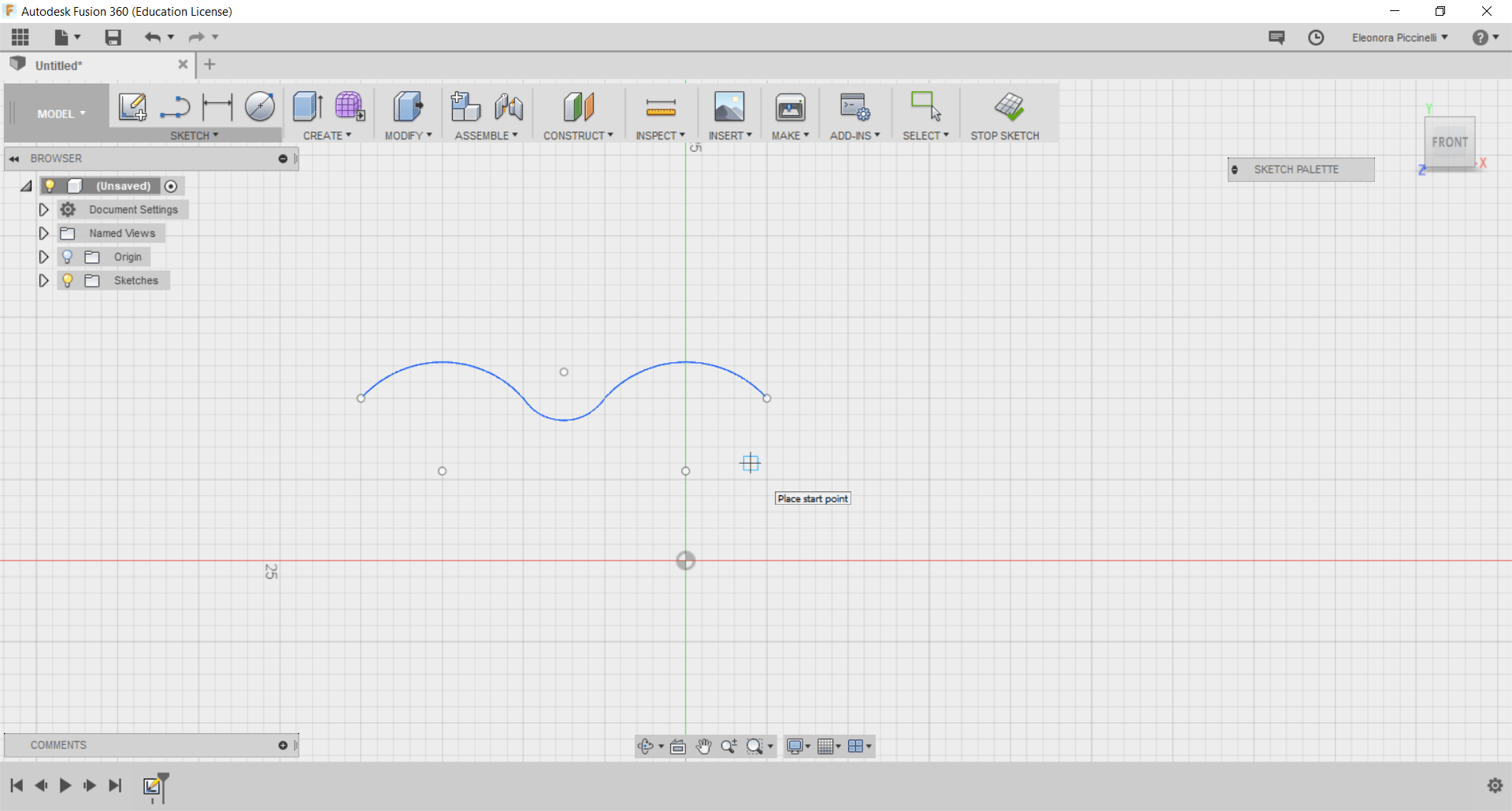
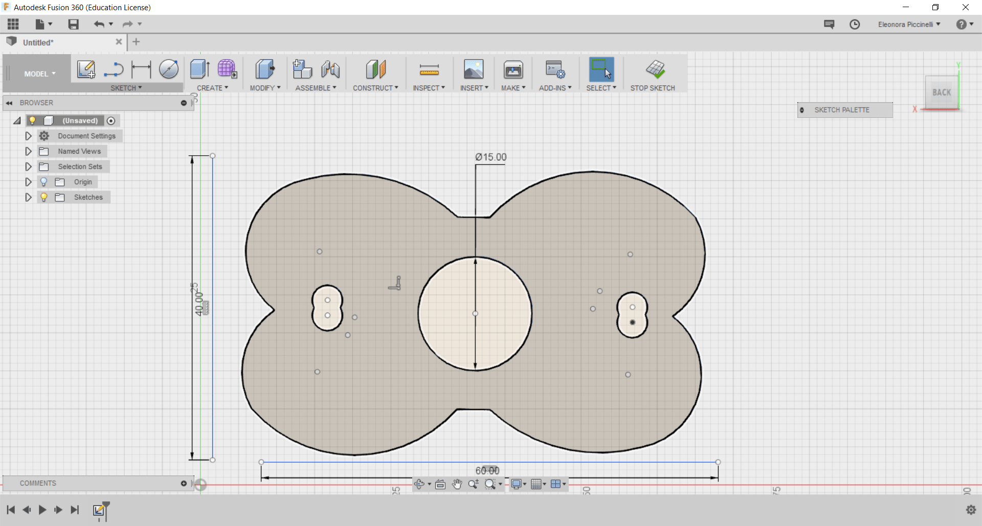
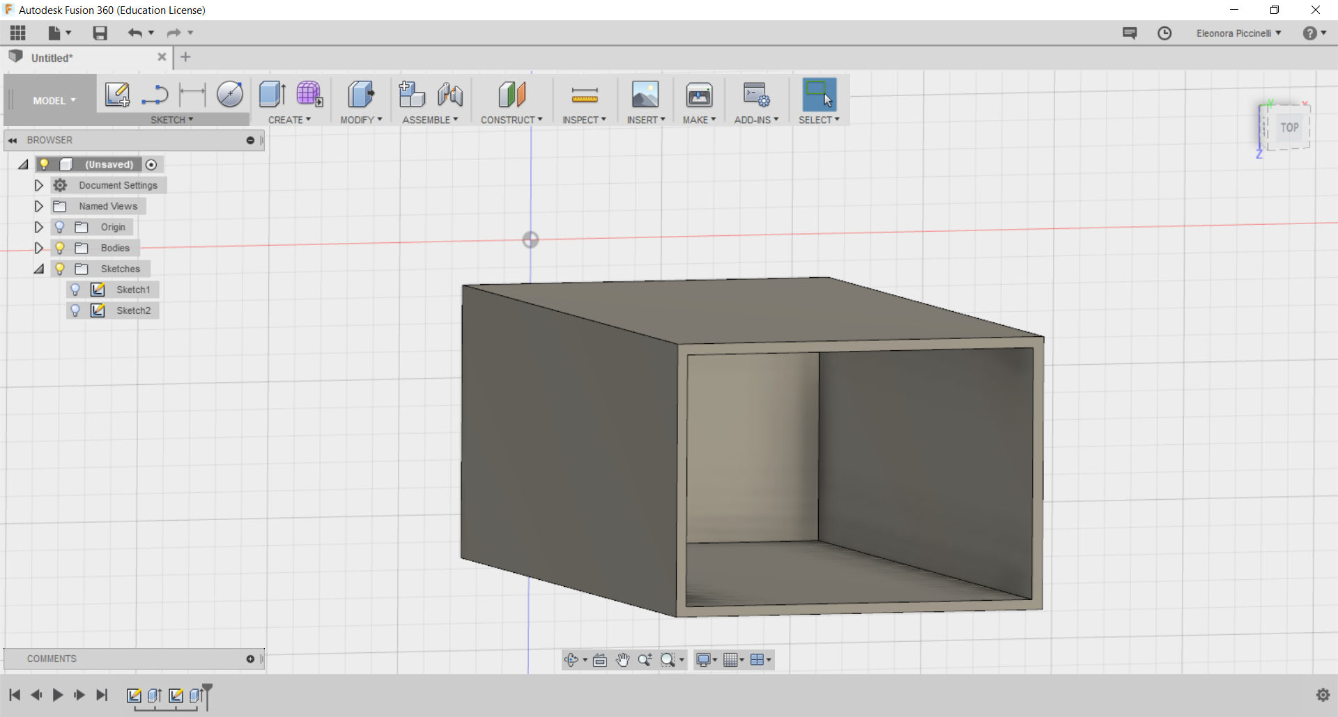
The following screenshots are going to explain step-by-step processes I did on Fusion360. As you can see, I started drawing a camber shape and I decided to focus my attention only on the half figure. Why? Well, I used the mirror function and I simply overturned my object.
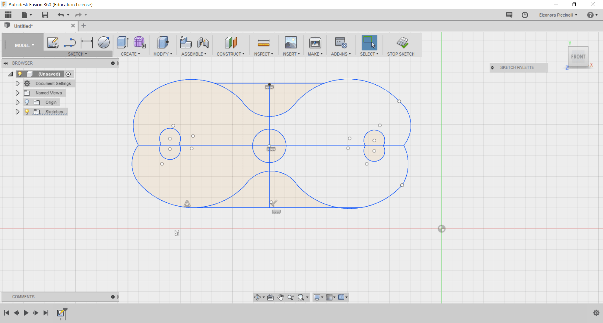
After having done the picture's outline, I set the values related to the extrusion and I tried drawing the soother in a real way.
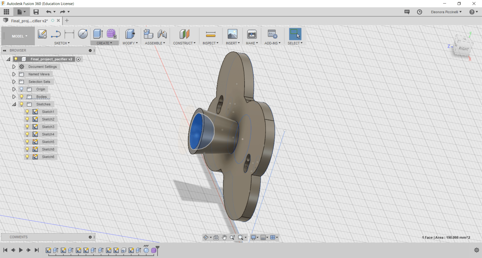
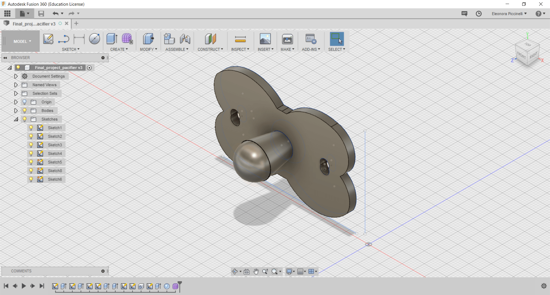
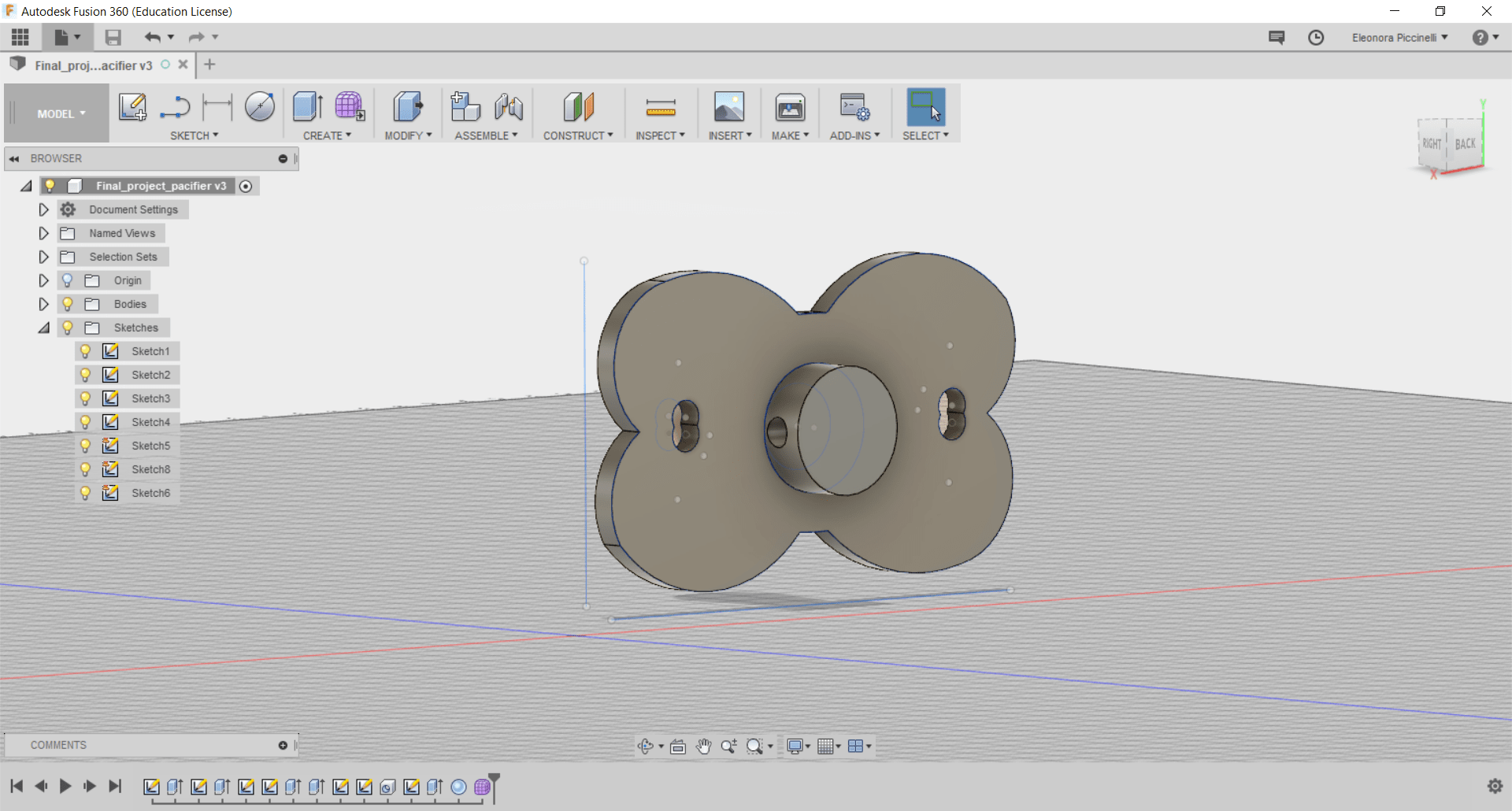
The final part will be bigger than the soother's starting point, so I set different dimensions to it. Then, I noticed that it wasn't regular, so I thought drawing a sphere would have been useful. The way of thinking was correct! I put the sphere shape at the top of my soother and I decided to pulled it half inside the pacifier's extension and the other half as a rounded final part of the whole figure. Finally, the last screen, shows the backside of my model. The classical ring is missed because I would like to add it after the 3D printing.
Update 4th June 2018:
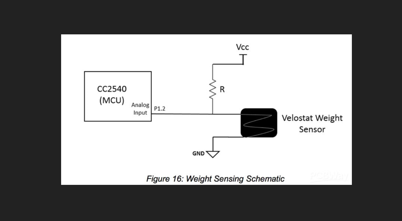
Today, I'm going to do a quick test with Velostat (as pressure sensor). To do that, I used the area of Velostat I wanted: it will work as a voltage distributor and the picture below will explain better what I what to say.
Considering which my intention was, I started working on it and I used:
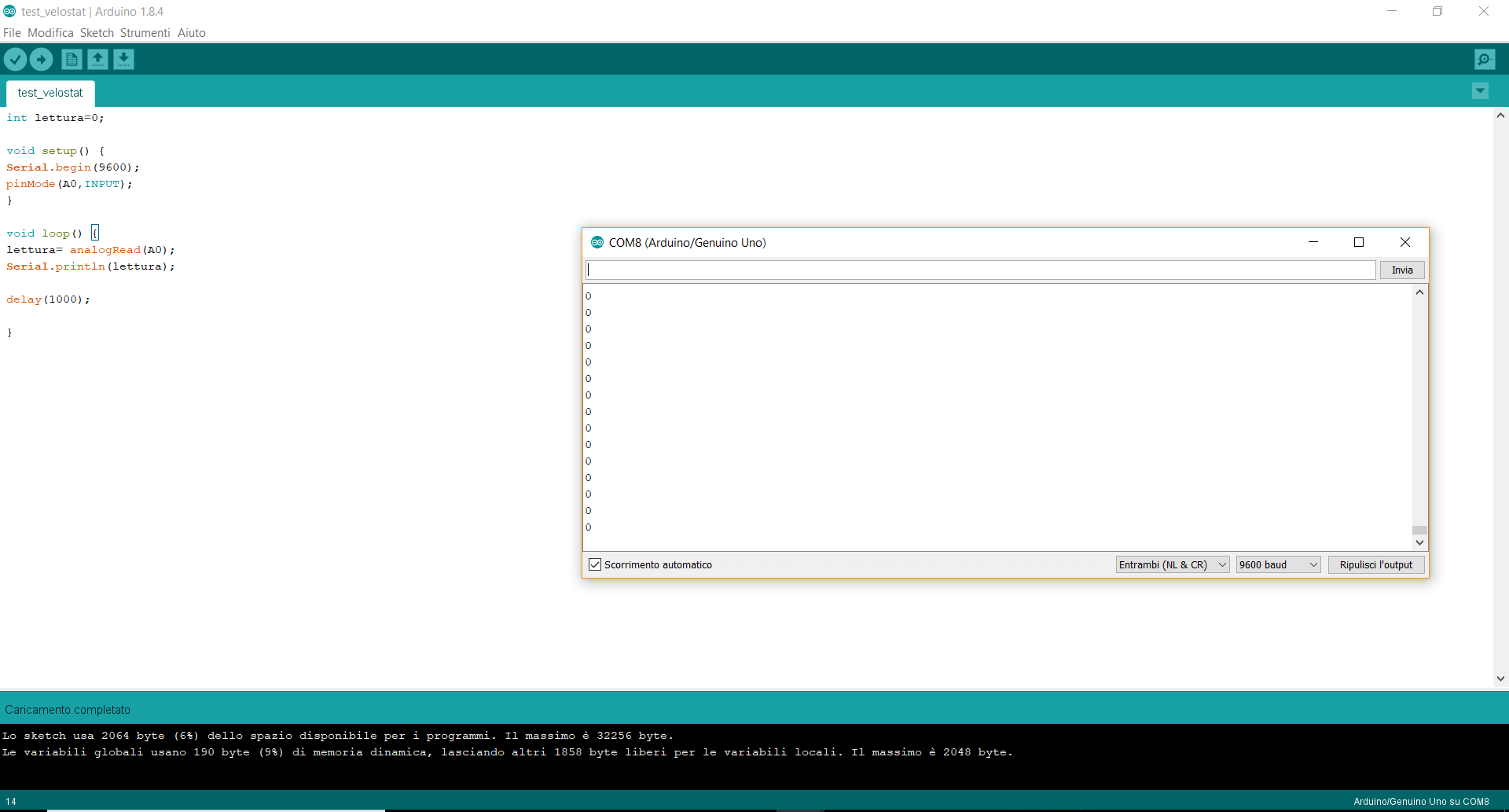
I started fixing the scotch on the velostat and I included the conductive thread under it surface. I thought it was enough and it would have been work. I bad fixed the thread because it would have been place between the velostat and the scotch with a wavy shape...and I completely did a mistake! I realized it only when I noticed my values on Arduino IDE didn't have changes according to the presence/absence of pressure.
The code I wrote for a quick test was the following one:
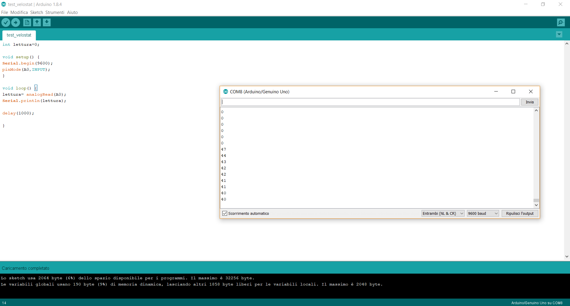
In the meanwhile I found an alternative solution and I thought using conductive fabric too would have been useful to see the pressure sensor almost complete. In fact I used two aligator clips to connect VCC and GND pins on the Arduino UNO board and I uploaded again my test skecth. I had to use the INT value because I would like to see appear numbers on my monitor. I connected the AO pins as an INPUT pin...it was linked to my sensor and it will print on my monitor the values (according to the resistor used and the velostat size = these two elements are dependent). More over, I saw the values appeared on my monitor was extremely constant. The day after, I repeated the same test and I noticed the velostat material is really delicate and it can be ruined easily. Anyway, on the Arduino IDE I finally saw different values. Consequently, the test code worked properly and the pressure sensor too. It gave me different values in terms of presence/absence of pressure.
Update 6th June 2018:
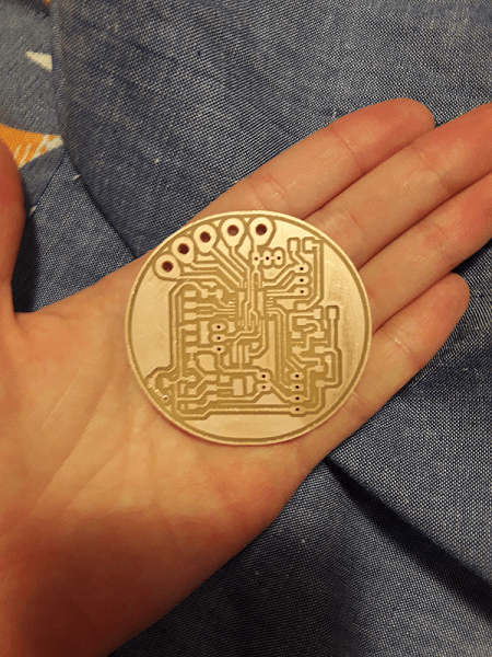
Up to now, I tested the pressure sensor I'm going to use, but I also used Eagle CAM to design my PCBs. Each one has Bluetooth pins and even if I used an ATmega 328p as MCU, I connected the TX and RX to two available pins. My choice is linked to the use of Software Serial and I'm going to program my boards as LilyPad. That's why I also used a 8MHz external resonator and I added the pads I needed. Last but not least, the project will work wirlessly, so I included two pins header for an external battery (9V) but I put a regulator on my boards because they will work at 5V. More than this, I added a 'POWER ON' led to test my board and give it a simple blink led before the final programming code. Here, there are both boards' screenshots:
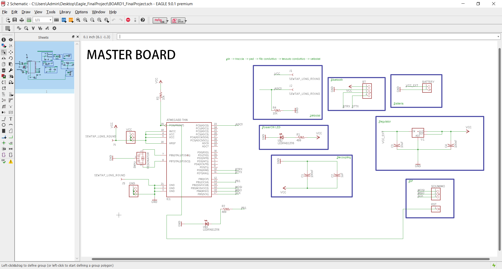
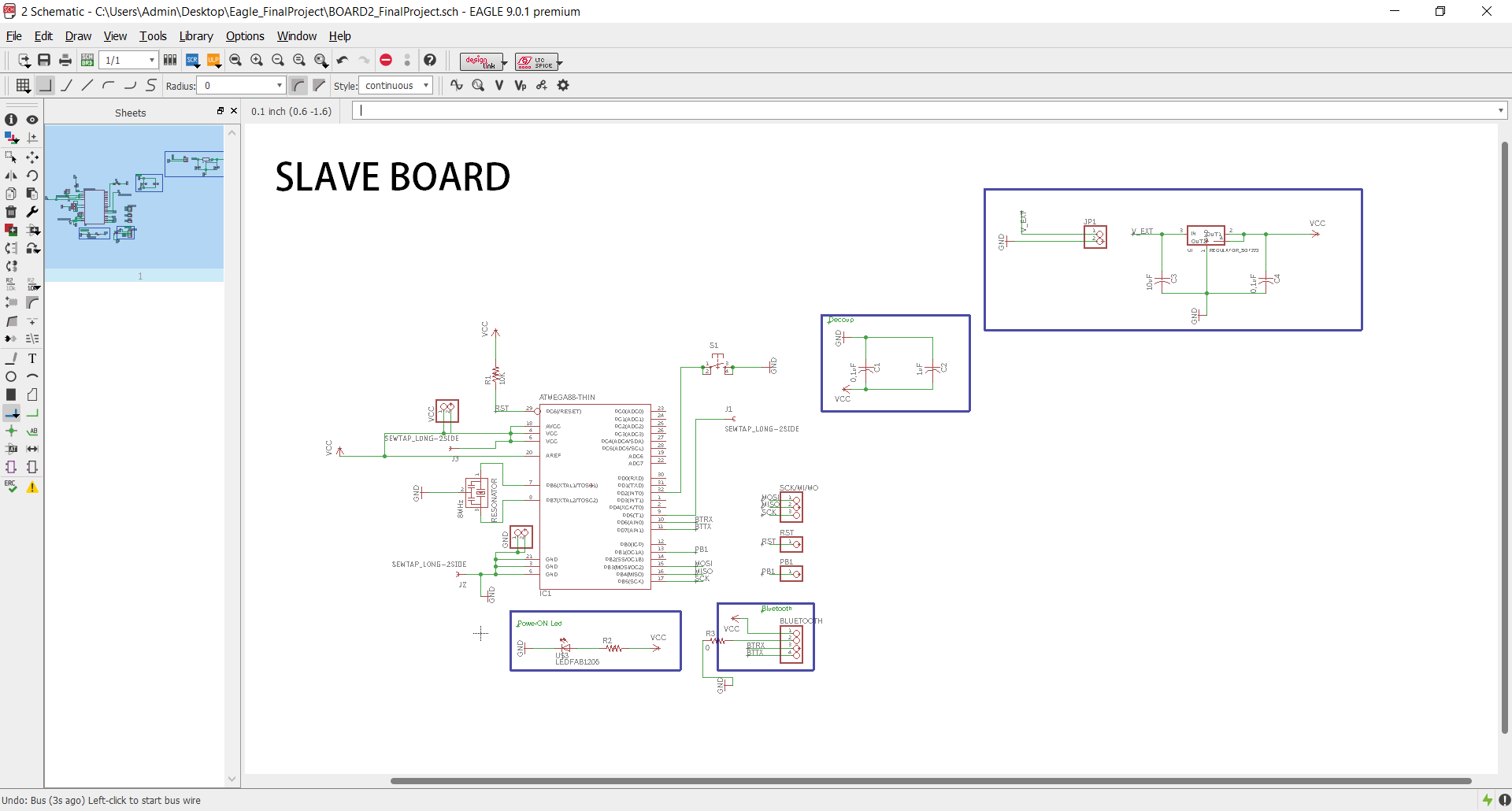
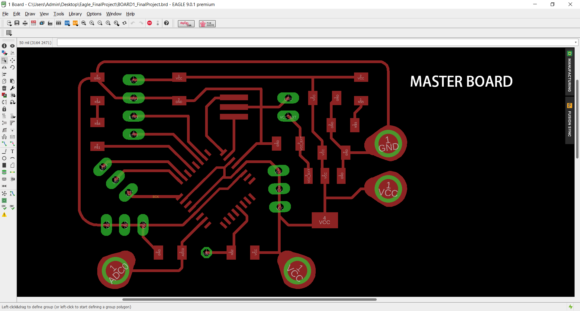
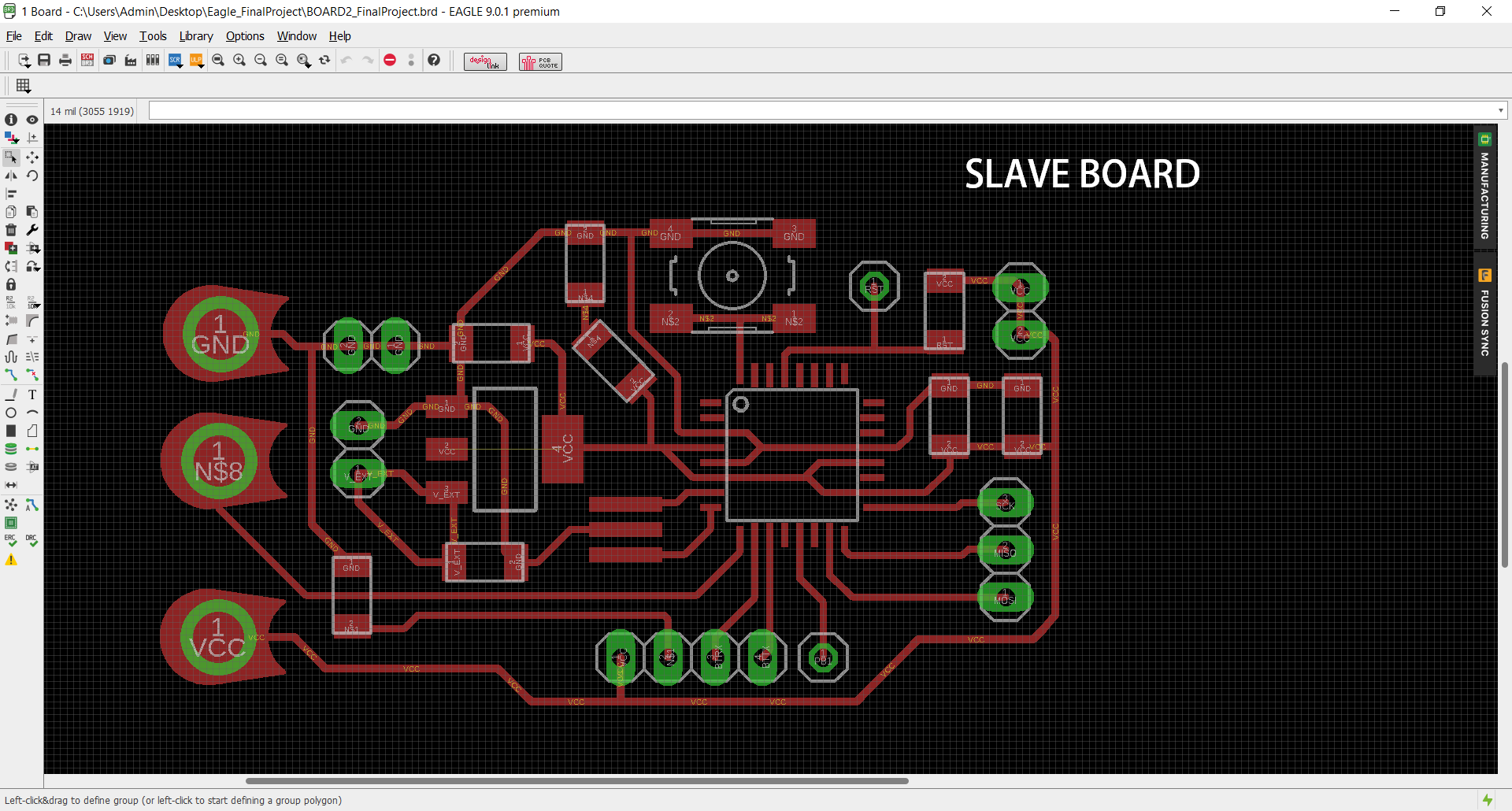
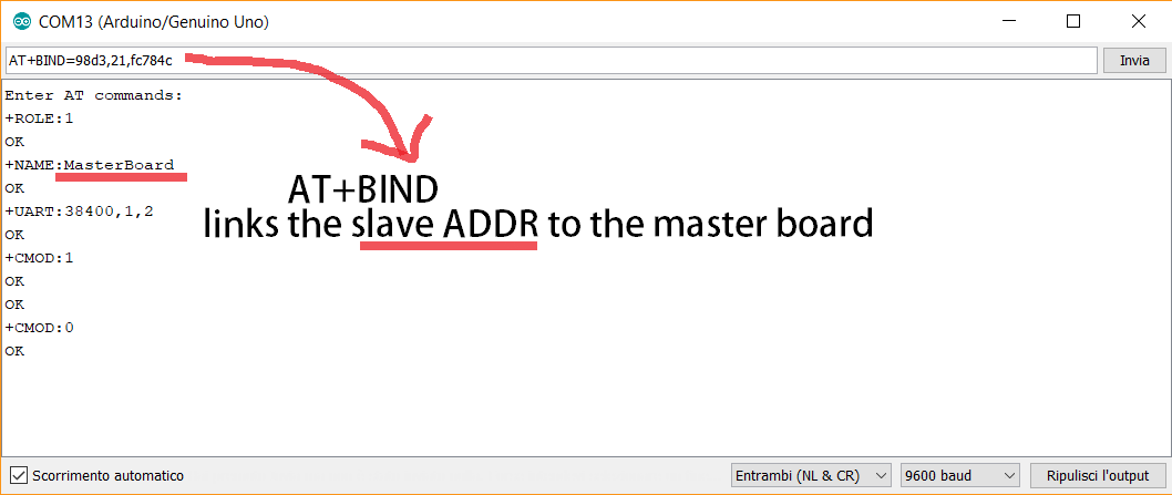
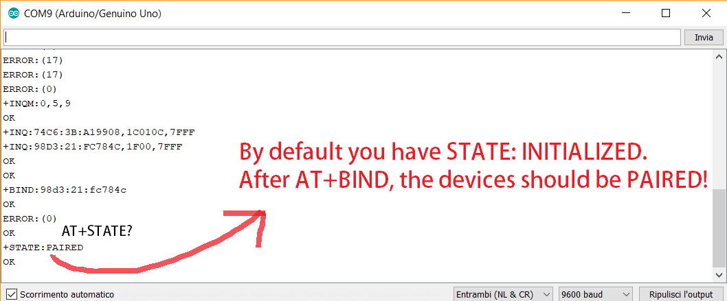
As can be seen by the second schematic file, I also added a button as interupt. To know more about its use, I went on Arduino documentation just typing Attach Interrupt. I looked for the digital pins usable for interrupt and I also noticed which was the recommended syntax to use on the programming code: attachInterrupt(digitalPinToInterrupt(pin), ISR, mode); (recommended). In my case the syntax code will be the following one: attachInterrupt(digitalPinToInterrupt(2), buttonpressed, FALLING);. Number 2 represents the pin I will use, 'button pressed' is the ISR and 'FALLING' is the mode. I chose it because it works when the pin goes from high to low and the button is used to allows people to decide: would you like to receive notification or not? Basically, I only thought about this kind of option because the project won't be a final prototype. In the meanwhile, I tested the HC-05 Bluetooth modules connection. To sum up the steps I followed, I watched this tutorial but it isn't complete at all because it doesn't explain you have to type AT+STATE? on the AT commands to see if your modules are paired or not.
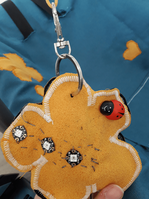
After that, I finally started writing my codes taking into consideration all the things I mentioned above. Then, I uploaded both codes on my PCBs and I tested them using an ARDUINO UNO as power supply. I noticed the elements were working correctly. I just had some problems with Flora Neopixel just because the conductive thread must be sewed very well. Sometimes they didn't worked properly, but I found a solution and I passed the threads inside their pads more than once. Doing so, the leds were well fixed on the fabric and they could work.
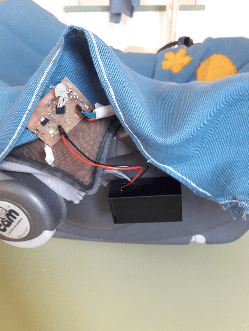
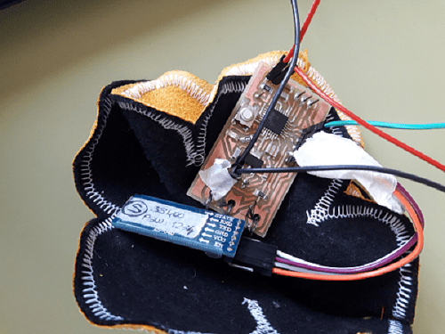
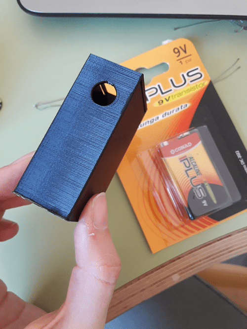
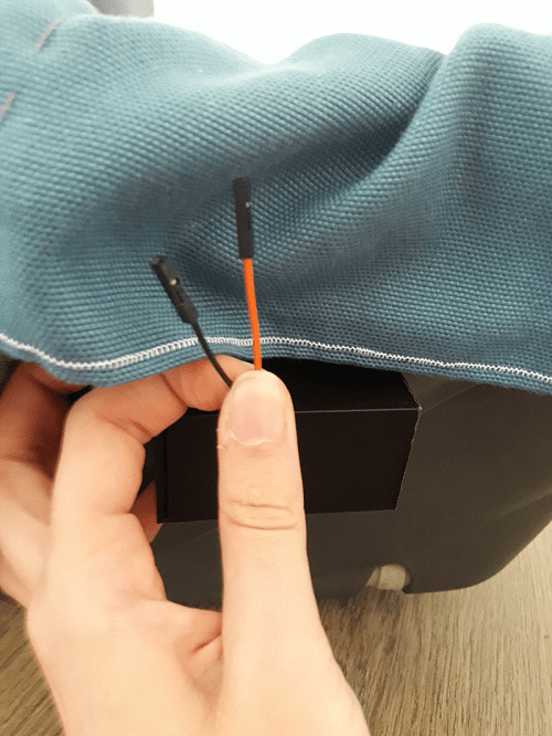
Finally, I just did a quick and simple external case for the 9V battery I'm going to use. I'll fix the little box on the child seat right side. In fact, the main board, will be sewed under the piece of fabric, the wires will be hidden and the final packaging will appear pretty organized.
The final codes are the following ones:
MASTER CODE:SLAVE CODE:
Sum up!
The final project development motivated me so much! Even if I have to move at my own pace, I can reach my small satisfactions and I like finding solutions to think about funcionalities first and aesthetical aspects then. The final shapes I created are the following ones.
Conclusion, improvements & redesign
How about final consideration? I'm happy about the result, because the elements I used all worked properly. It doesn't deny the fact, the pressure sensor would have been changed as something more resistant and reliable (in terms of values). So, thinking about a possible redesign I could improve the project doing the following things:
Download:

This work is licensed under a Creative Commons Attribution - ShareAlike 4.0 International License.