
Things to do :
- Design and build a wired and/or wireless network connecting at least two processors
- Include original code
Bluetooth
For this weekly assignment I decided to focus on the Serial comunication,espacially on the bluetooth module.As always the first step was to google for some tutorial even if,due to my background,I already known something about computer's comunication.Those links listed below are the ones I found more useful :
Bluetooth comunication is a wireless serial comunication,perfect for my final project: turbines the kids will build will have to talk to a central electronic board situated a few meters away from them.The first important limitation is that bluetooth modules can only be paired two by two and another important factor is the price of each module ( 8€).
However my goal for this week was to make two electronic boards talk via bluetooth,in particular I want them to send and read integer values.
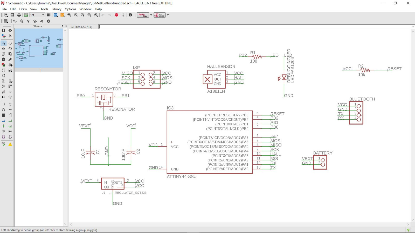
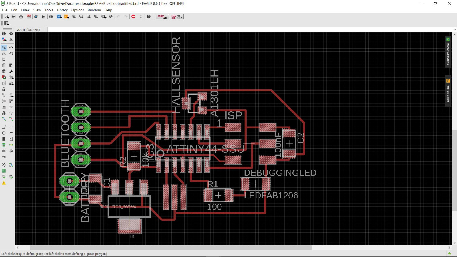
The electronic boards I used were the one I made for Week 11 : Output Device and another one very very similar to that one,so the information about the designing process are in this week's documentation:
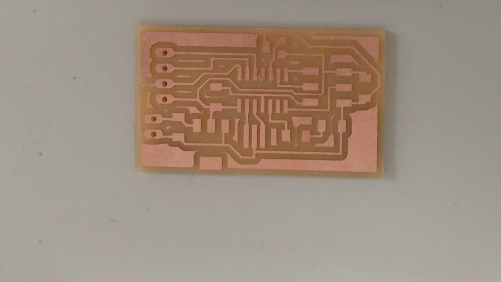
Milled :
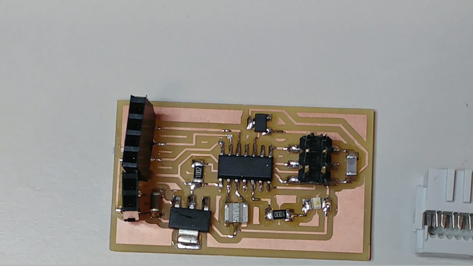
and soldered:
Pairing Bluetooth: AT Command
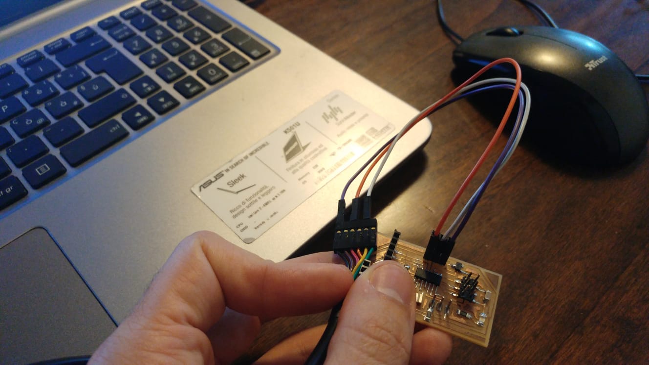
I started whit the pairing of the modules,so i hooked everything up in this way ,in order to enter the AT Mode: (source)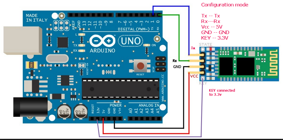
To make this process I followed this tutorial and next I setted the baud rate at 9600 whit AT+UART=9600,0,0 and then the modules started to blink like they were paired ( as the video shows).
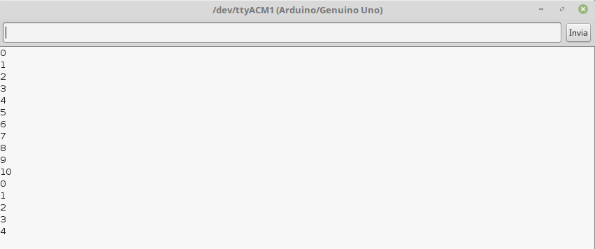
Next I tried to send some numbers from my board ( The Board 1 shown in the image above) to an arduino UNO.
I connected GND and VCC of the HC05 module to the GND and VCC of the Arduino and TX and Rx of the HC05 module to the pins 11 and 10 of the Arduino
The code for my board :
The code in the Arduino where I opened two serial ports (one SoftwareSerial) in order to see if the comunication worked well:
The result :
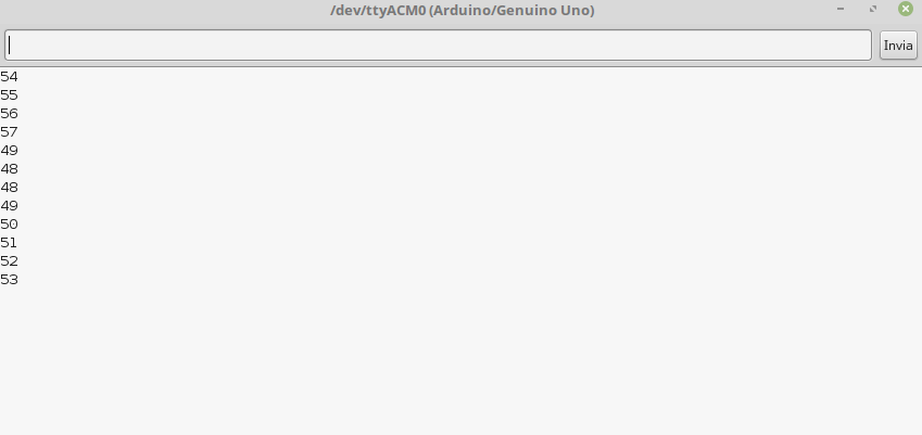
It wasn't what I expected.Why did it happen?
I searched on the documentation of Serial.print() for some useful information and I found something that could help me : Prints data to the serial port as human-readable ASCII text.
So I looked at the ASCII table :
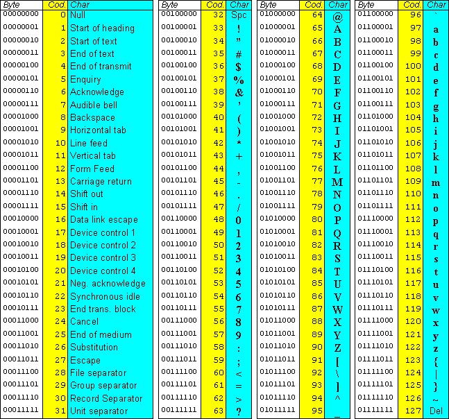
and when I looked back to the code and the output I get,I figured out how the int values are managed in the serial comunication.
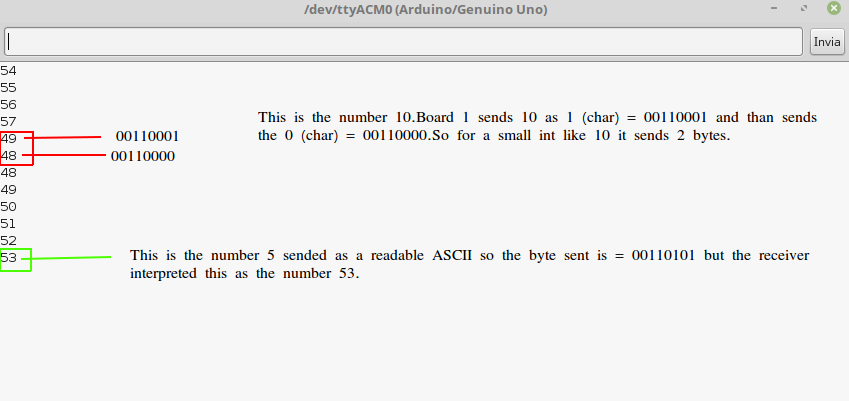
The improvement I had to make was to subtract the ASCII values of 0 (48) and manage the higher than 9 , 99 , 999 and so on ( because until the number 9 it sends 1 byte , next from 10 to 99 sends 2 bytes , next from 100 to 999 sends 3 bytes and so on).
That is the code I made to solve this problem and it worked :
At the end I changed the declaration of a in the code of the sender and b in the receiver in INT instead of UINT8_T,due to the fact that the maximum values storable in a uint8_t variables is (2^8)-1=255 and probably i'll need to manage higher numbers.
Board1 to Board2
Once my Board1 comunicated succesfully whit the Arduino UNO I flashed this code to the Board2 .I used the SendOnlySoftwareSerial to have a feedback of the comunication.I have PA2 exposed whit a male pin header in the middle of other 2 pin header (GND and VCC) so I made this bridge from my board to an FTDI cable :
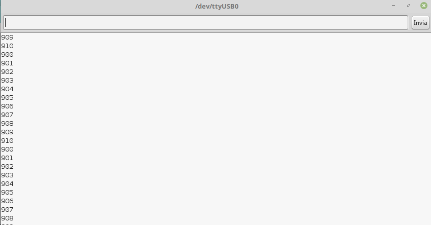
I changed the values that the Board1 sent,instead of 1 to 10 it sent 900 to 910 just to check if my code worked well even whit 3 bytes sent.
I powered Board1 whit a 9V battery and the Board2 whit the FTDI cable :
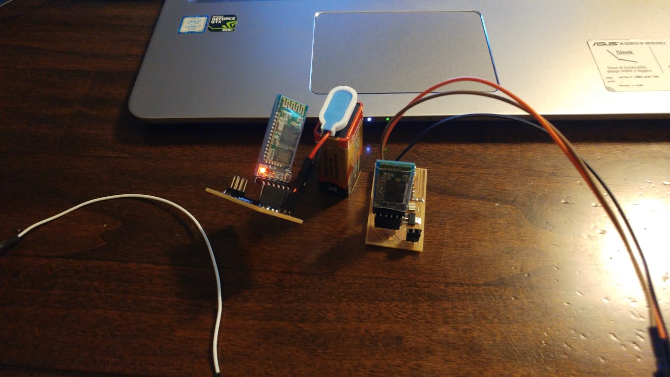
And it worked !
I2C
Last but not least I tried to figure out how the I2C protocol works.I started reading something about it(Wikipedia , Sparkfun).Once I had the basic information I linked my boards as descripted by the I2C protocol:
We need 3 wires between the two board:
The boards I used were the Hello board made for Electronic Design and the board made for Input Device. The two boards are based on ATtiny44 so I had to check the datasheet to know witch pins are dedicated for SDA and SCL
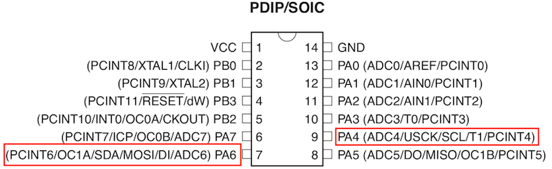
These two pins are used by the ISP (MOSI and MISO) so they were already exposed by the 2x3 pin header that every board I made has.
Coding
Since Arduino's Wire library can't be used on ATtiny44 I installed TinyWireS and TinyWireM libraries , the modified version of Arduino's Wire library that can work whit ATtiny44.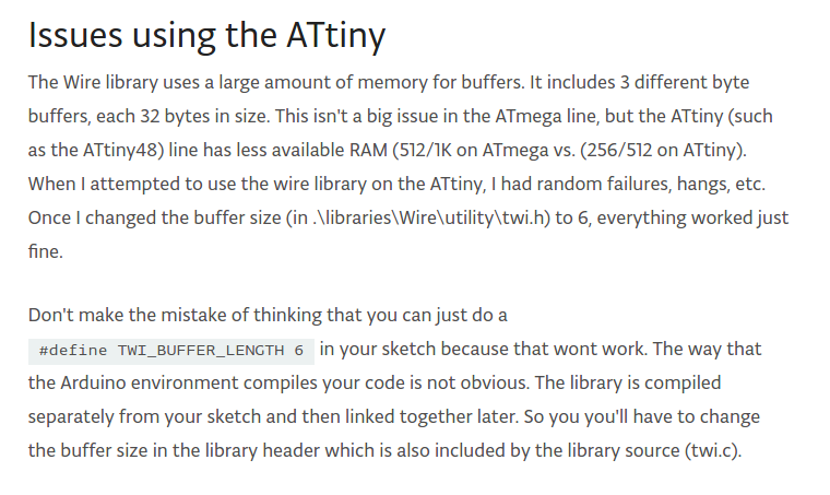
Installation of TinyWire
I opened the Arduino's folder called Libraries whit the Shell and I cloned the repository of the TinyWireS library (git clone SSHKEY):
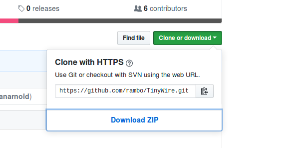
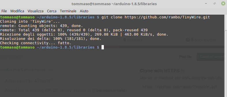
(Same procedure for TinyWireM)
Slave's Code
and Master's Code
It didn't work ,I hope to fix what is wrong as soon as possible.