Things to do :
- Group:characterize the specification of your PCB production process
- Individual make an in-circuit programmer by milling the PCB
- Individual optionally trying other processes
ISP programmer,milling the PCB
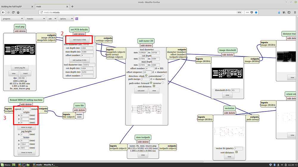
For this week assignment we had to make an in-circuit programmer by milling the PCB.We could chose from a list of ISP based on ATtiny45 or ATtiny44.Every single ISP of the list is well documented,I chose to make the FabTinyISP .First of all I downloaded the png files.One for the inner traces and one for the outline.Then I created the RML files whit mods.cba.mit.edu :
(Hold the left button on the img to zoom in)
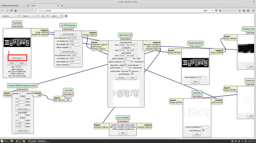
Since I first selected the png of the inner traces I selected the "mill traces(1/64)" button and then I setted the origint to 0 in order to setting it up later whit VPanel.
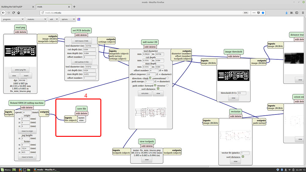
To save the RML file I added the module save file by clicking on add server module in the drop-down menu modules
Then I calculated the milling lines.
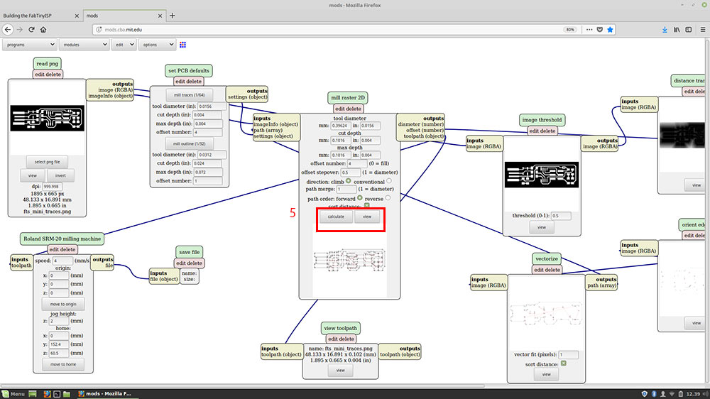
TIPS : I setted 4 in offset number,but if you want the machine to mill the board untill is clean you have to type in 0 or -1.
I followed the same steps to generate the file .rml for the outline, but instead of selecting mill traces(1/64) I selected mill traces(1/32)
VPanel
I took an image from Flavio Lampus in order to explain how VPanel works,and I do we use it.It's been very usefull to me: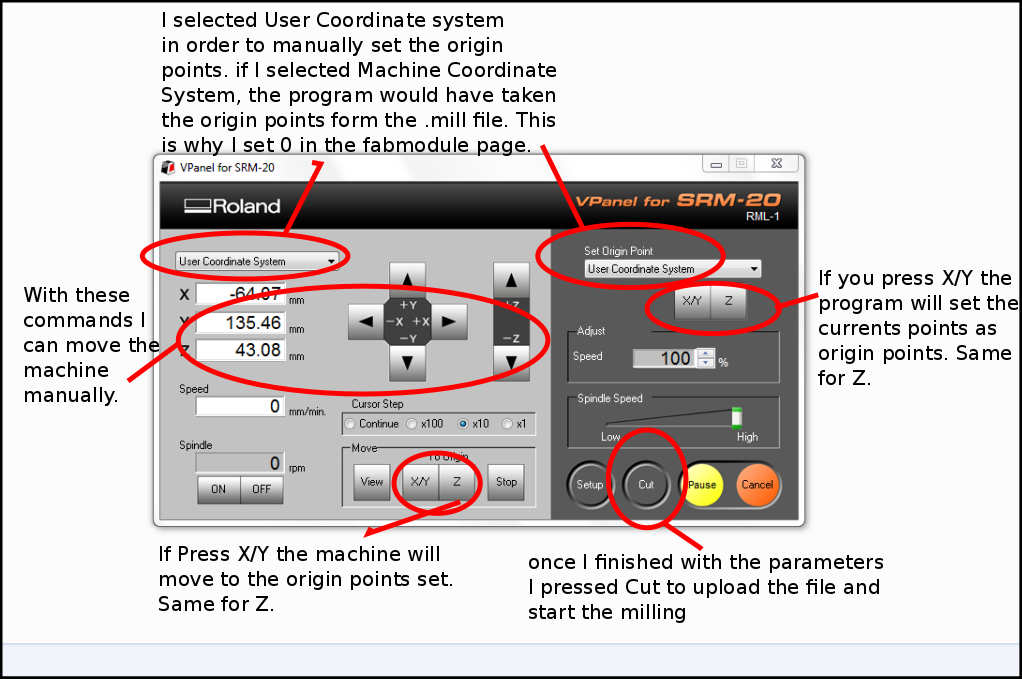
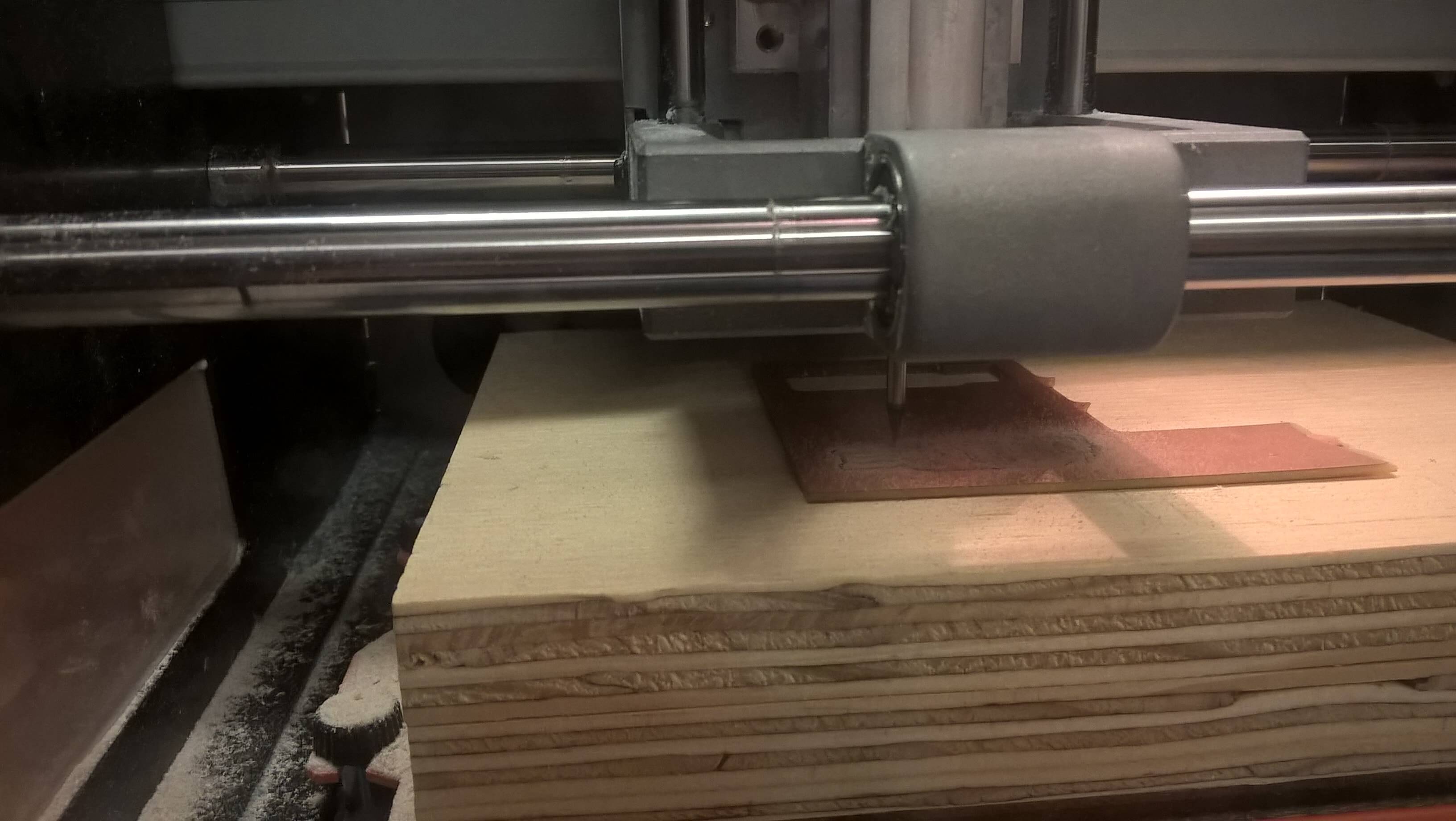
Milling
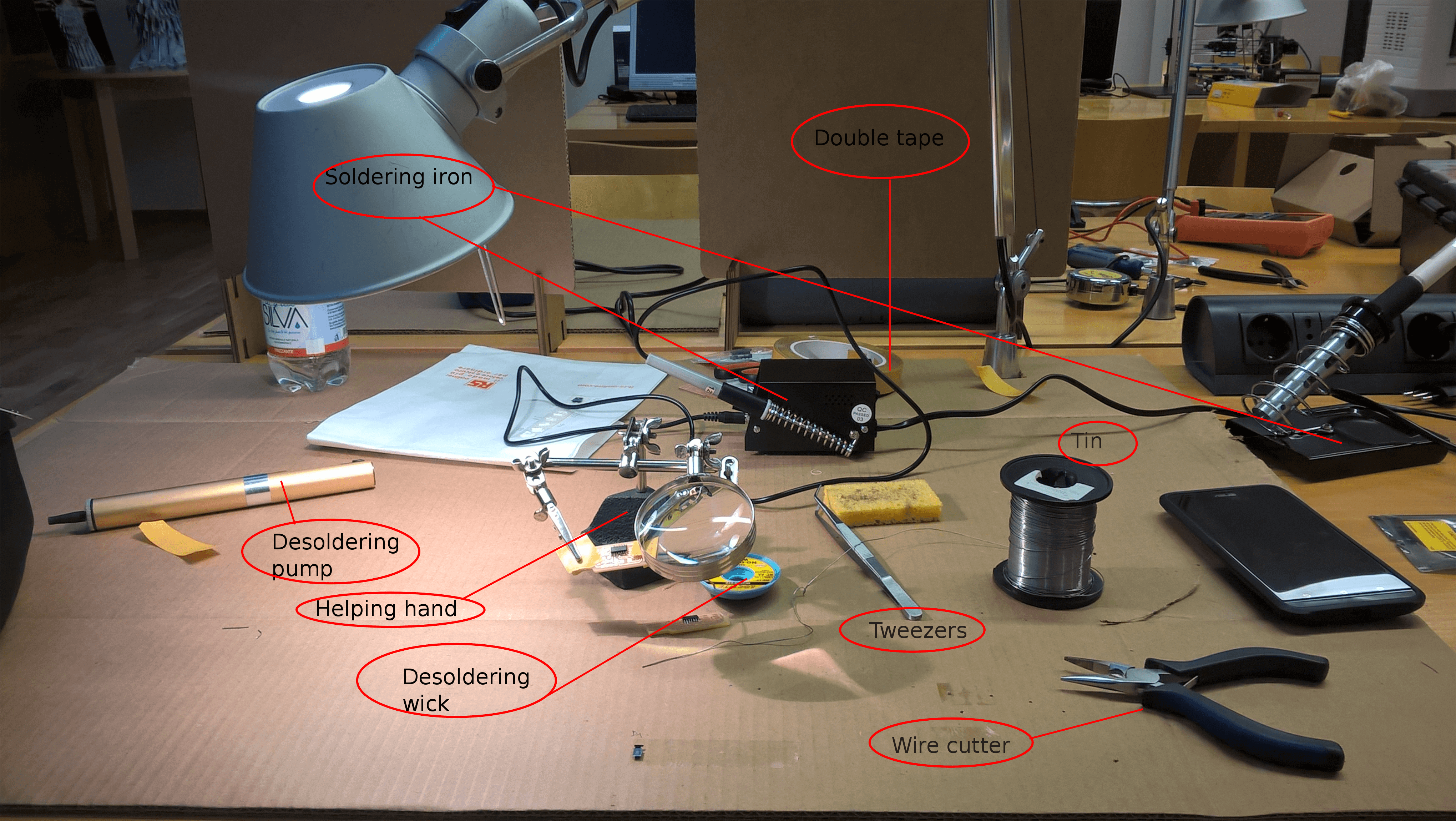
Before sending the milling file that I made whit fabModules to the Roland via VPanel,I gathered the end mill I was going to use: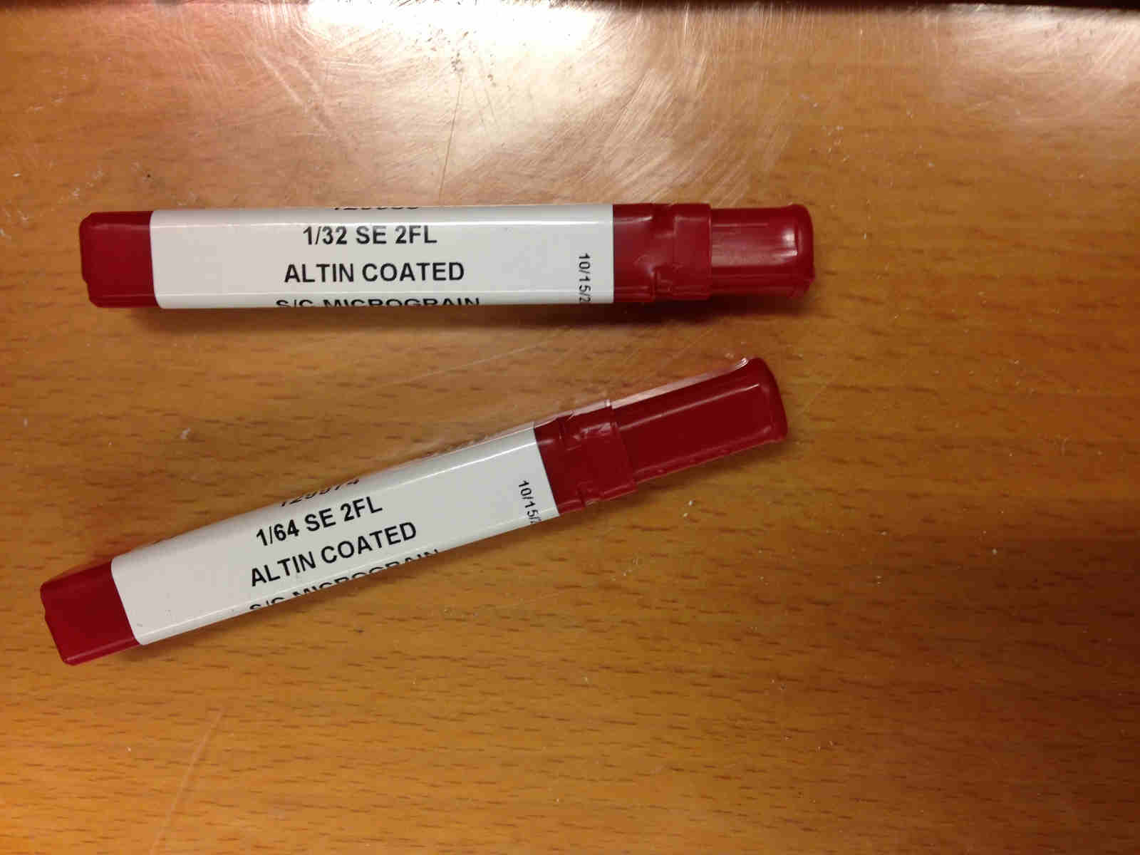
Putted double-sided tape in copper sheet rear and stuck it firmly to work plate.
Once I've chosen the x,y coordinates to start the milling process, I pushed the Set X/Y button in the software to zero them. The same operation had to be done for the z, meaning that you have to lower manually (slowly and whit controlled steps) the milling tip over the board and after you've reached an height that is just enough, you have to manually un-screw the tip from the spindle, push it slightly over the PCB surface and screw it back.
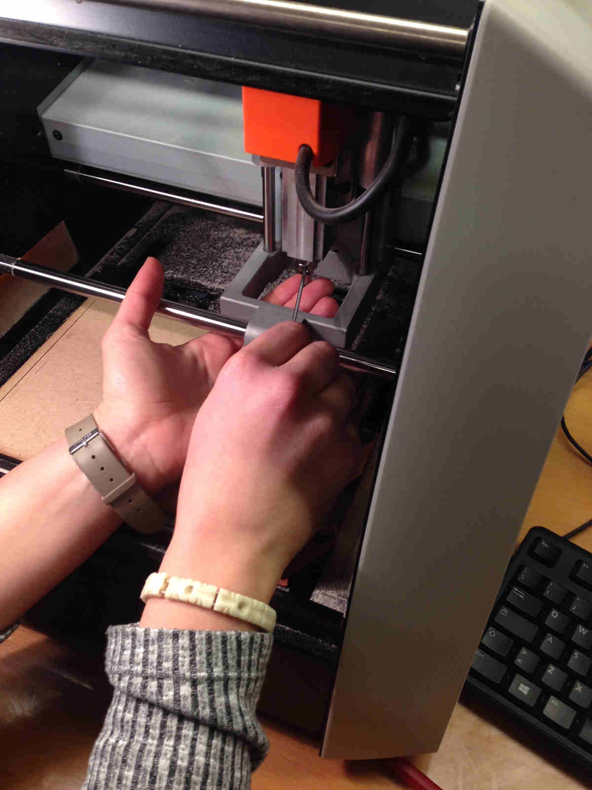
TIPS:always put your fingers under the tip when you unscrew so as not to let it fall ruinously.
photo tooked from Silvia
Soldering
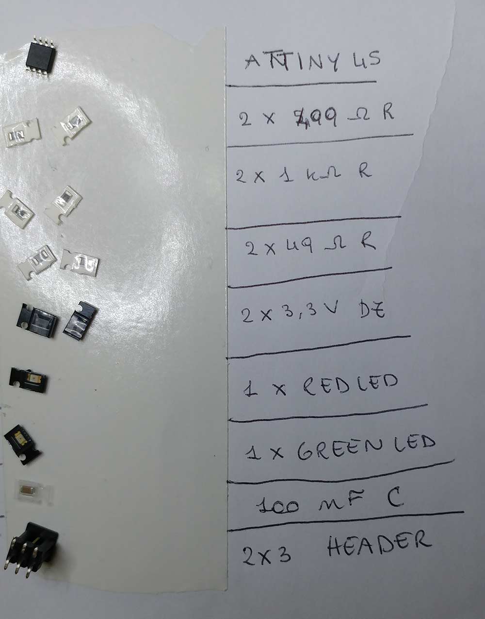
I enjoyed the experience of learning how to solder smd components.Every components are very small,I didn't expect to be able to solder something so small.Our instructor Matteo taught us how to do it,and i cleared all my doubts by watching this video.Before startig to solder I made the BOM ( Bill of materials).The components that the FabTinyISP requires are listed in the documentation of the board.
Our soldering station is a Lafayette ssd-87,I setted the temperature between 320 and 330 celsius and turned the aspirator on to avoid to breath the fumes.
Here is a picture of Flavio Lampus showing everything I gather every time I have to solder:
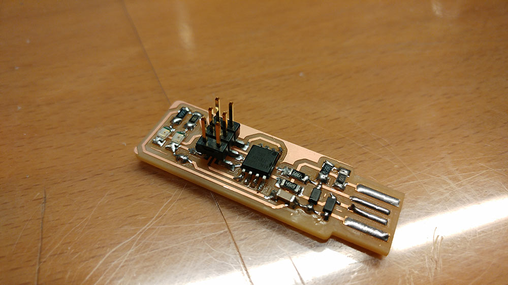
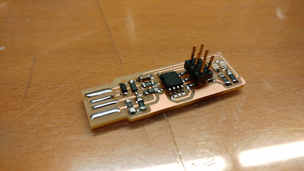
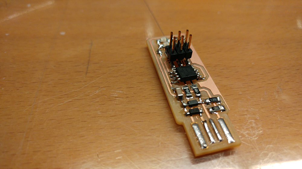
I followed the advice of Brian and the first component I soldered was the ATtiny45. And there is my final ISP programmer:
Programming the programmer
Hold the left button on the images to zoom in
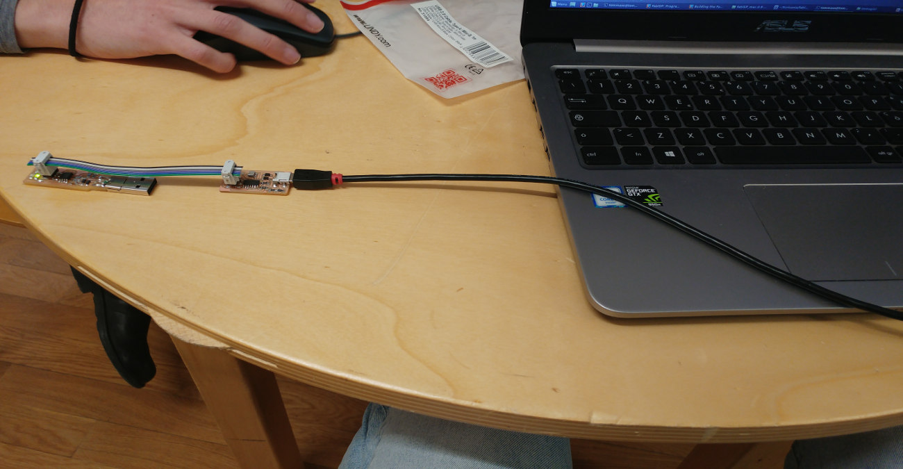
Once I hooked everything up as shown in the image above I started programming the programmer.
It's all well explained in the documentation of the FabTinyISP :
"Before you can build and program the firmware onto your board, you need to set up your development environment. You'll use this setup for all of your AVR programming for the class. The setup differs a bit for each platform, but once the software is installed it should work more or less the same on each platform."
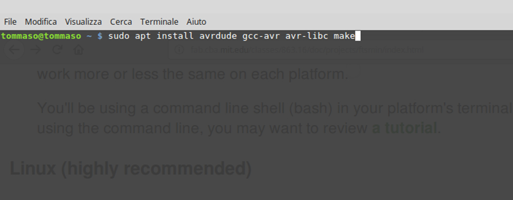
For Ubuntu and other Debian-based distributions, enter the following command, followed by your password when prompted:
sudo apt install avrdude gcc-avr avr-libc make
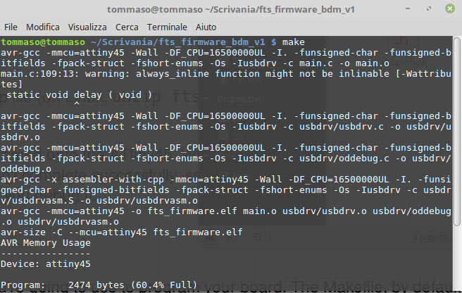
And I continued following the steps listed Here.So I opened the terminal in the firmware's folder I downloaded from the page linked above at the Paragraph called Get and Build the Firmware.
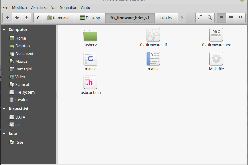
Results in the folder :
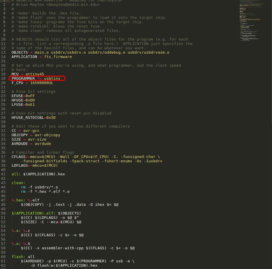
First, update the Makefile for the type of programmer you're going to use to program your board. The Makefile, by default, assumes that you're going to use a programmer in the usbtiny family (e.g. another FabISP board). If you're using a different programmer, first figure out what avrdude (the programming software) calls it
Edit the file called Makefile. It is important to use a text editor intended for programmers; programs like Notepad or WordPad can add formatting information that breaks the file. On Linux, gedit (GUI) or nano (command line) are good options; Windows users might want to use Notepad++. TextEdit on OS X usually works, just make sure you save as plain text and not RTF (and make sure no ".txt" gets added to the filename). Sublime Text is another popular choice on several platforms. In general whatever you use to edit your HTML code is probably an okay choice. Near the top of the file, find the line that says:
PROGRAMMER ?= usbtiny
and change usbtiny to whatever programmer you're using
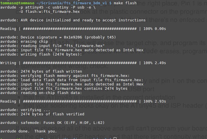
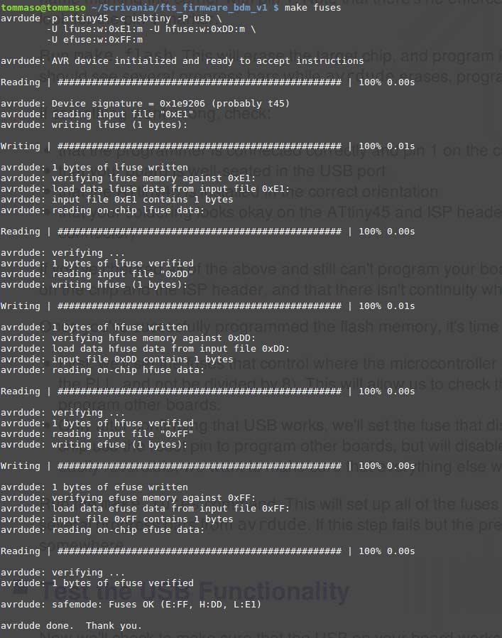
Luckily everything went fine and the programmer was succesfully programmed.
So I tried to plug it in my pc to see if it recognize the fabIsb :
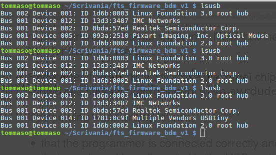
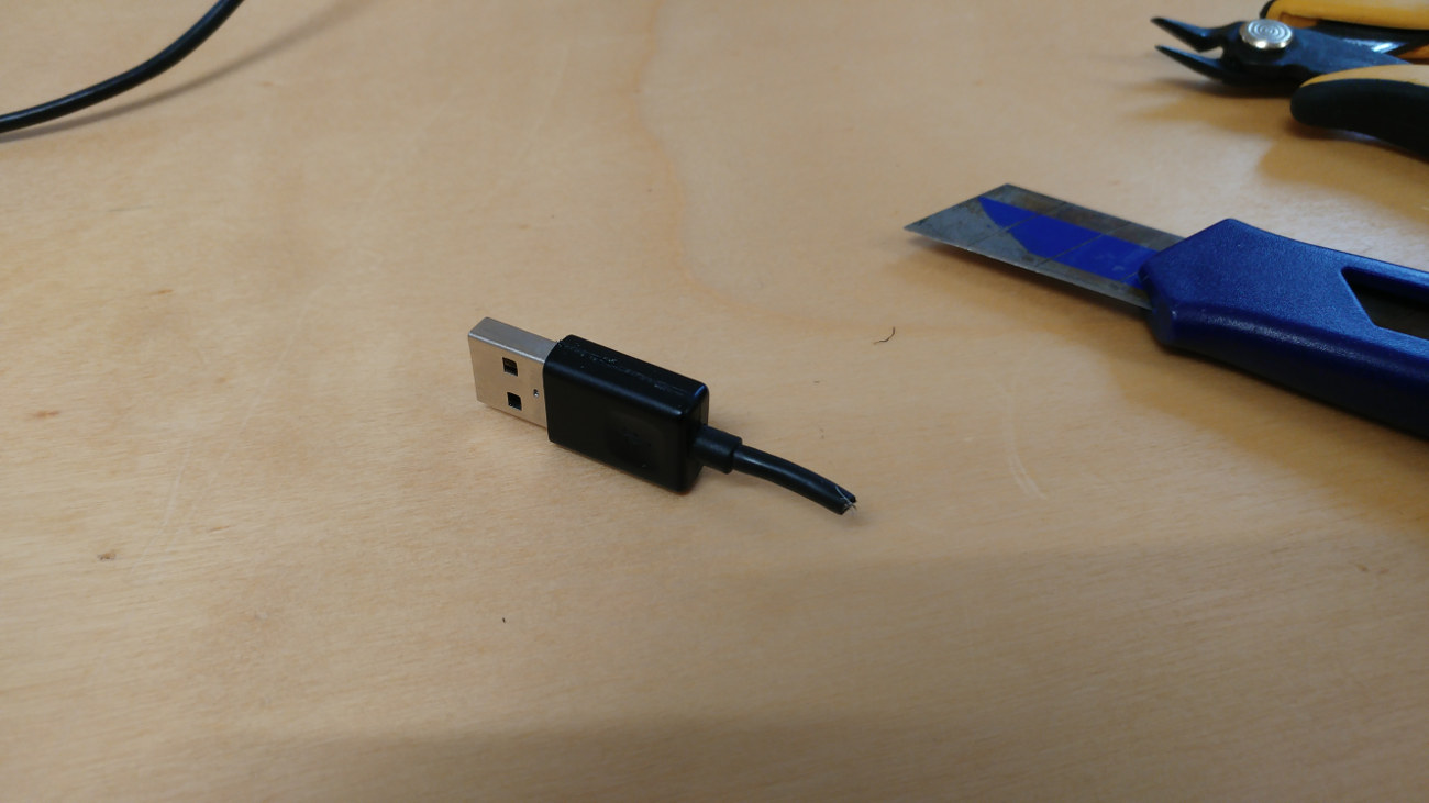
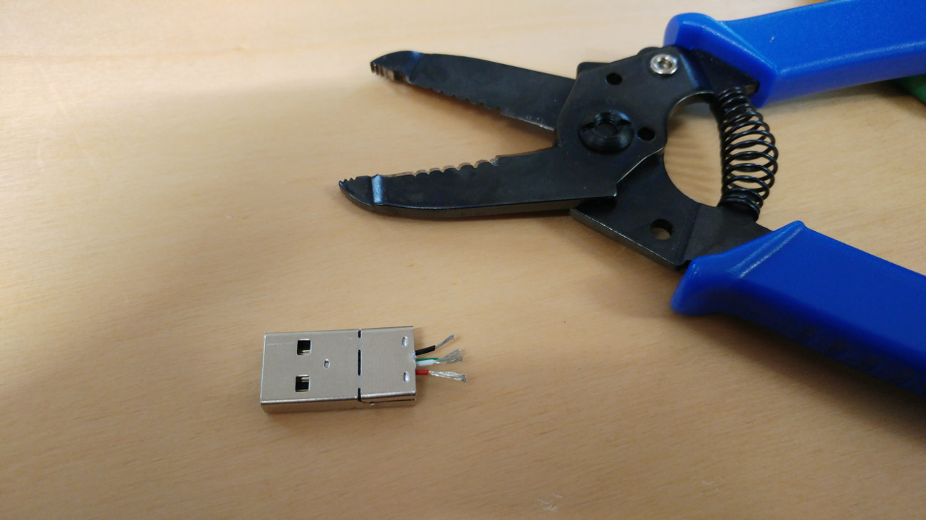
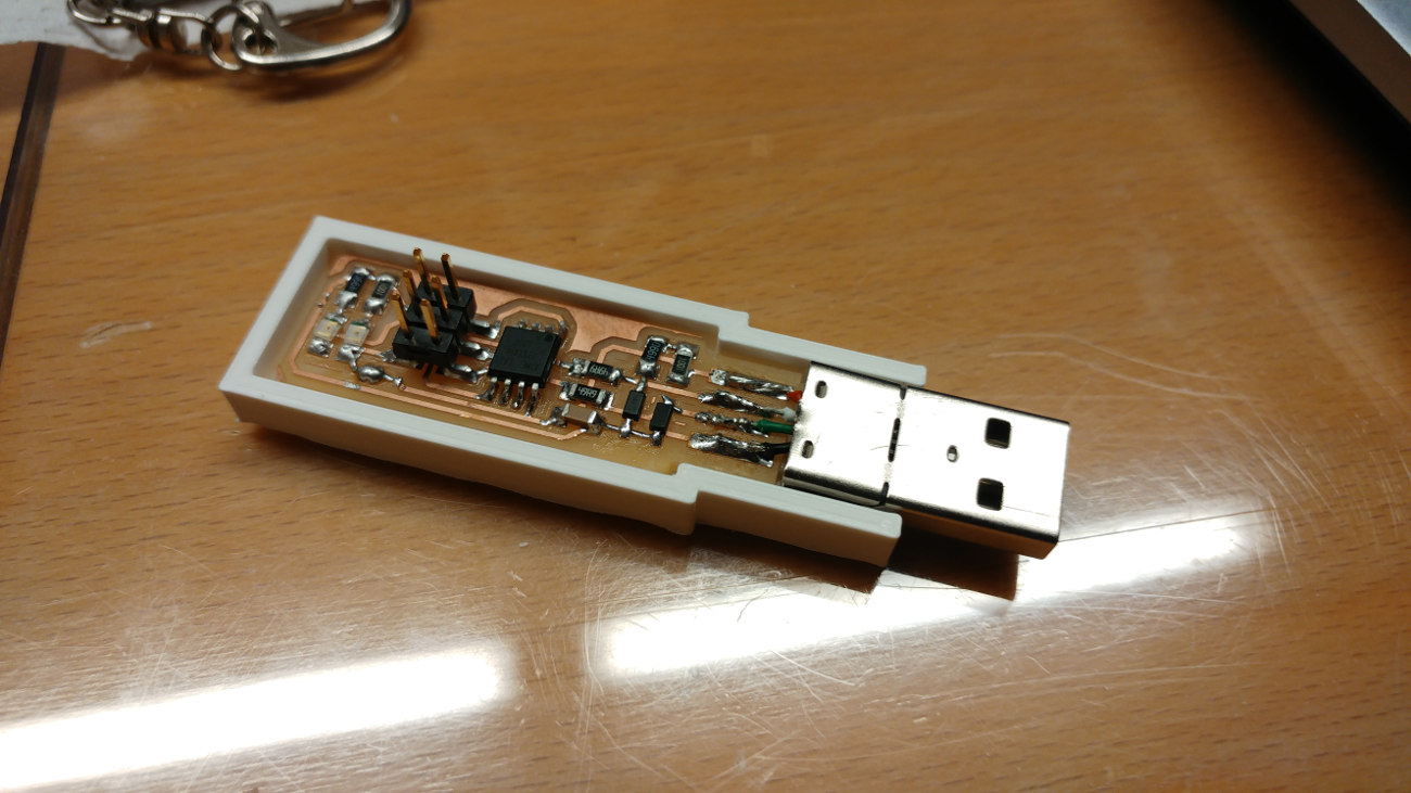
It had some problems due to flawed usb connector.So I solved this problem extracting a usb male connector from an old cable and soldering it to my programmer and I designed a simple case in solidWorks and Pietro kindly 3Dprinted it for me.