
Things to do :
- Group : Test the design rules for your printer(s)
- Design and 3D print an object (small, few cm) that could not be made subtractively
- 3D scan an object (and optionally print it)
3D Printing
This week's assignment was to design and 3D print an object that cold not be made subtractively.Considering the fact that I will deal whit rotating axis of the turbine I tried to 3D print a ball bearing.I designed the object in solidWorks once I saw this and this tutorial .
Update 28/05/2018
My instructor made me notice that I didn't documented the designing process for the ball bearing.Obviously I lost the file I made so I had to redraw everything.The dimensions are not the same but the processes are.
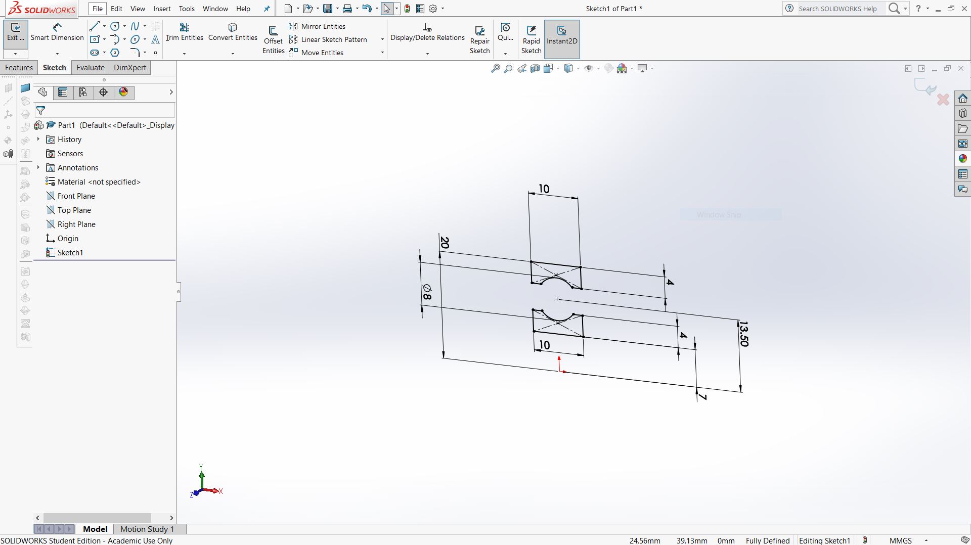
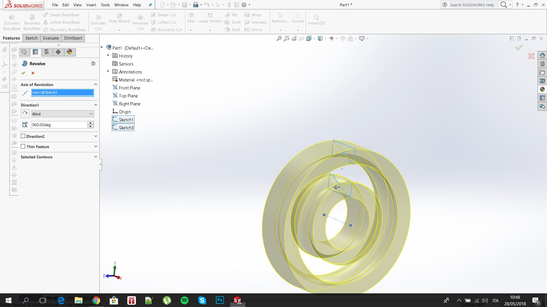
Once I draw the section of the ballbearing I used the revolve feature as shown in the image below
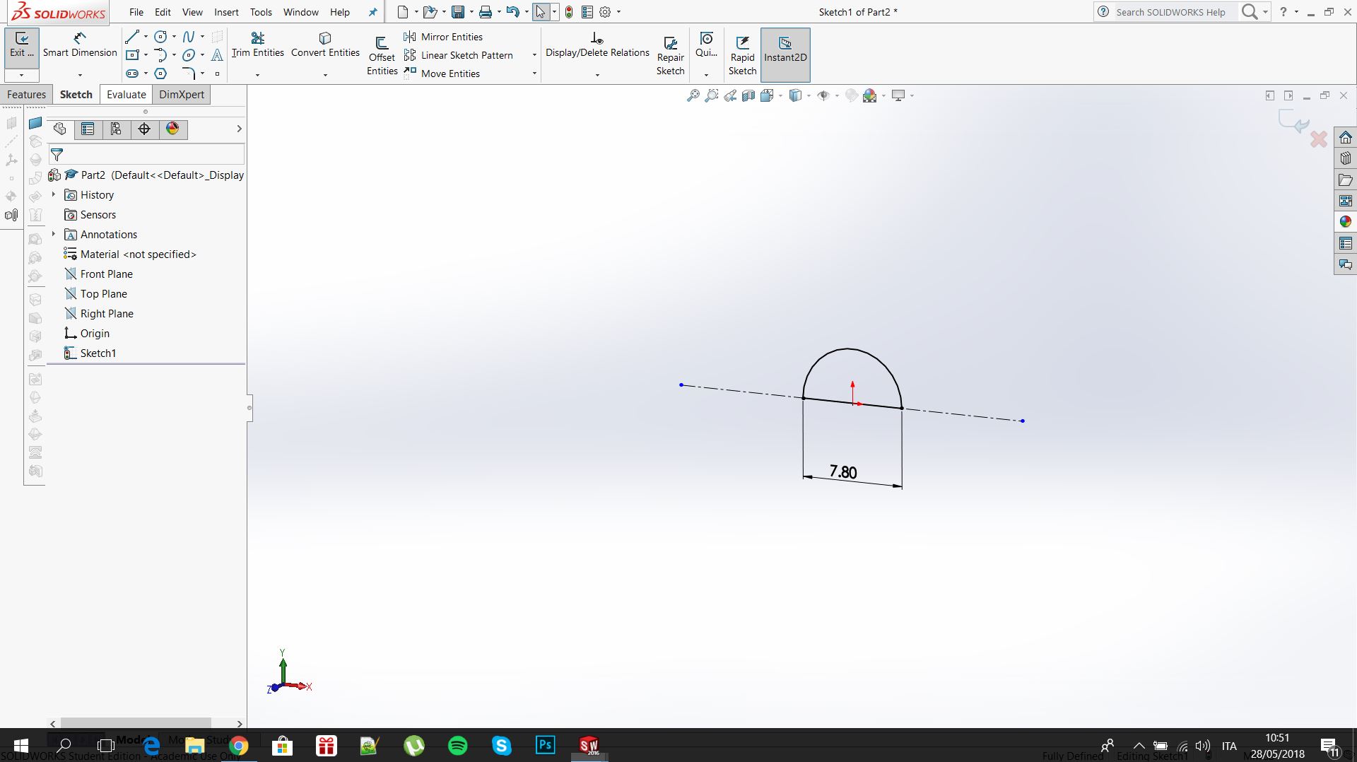
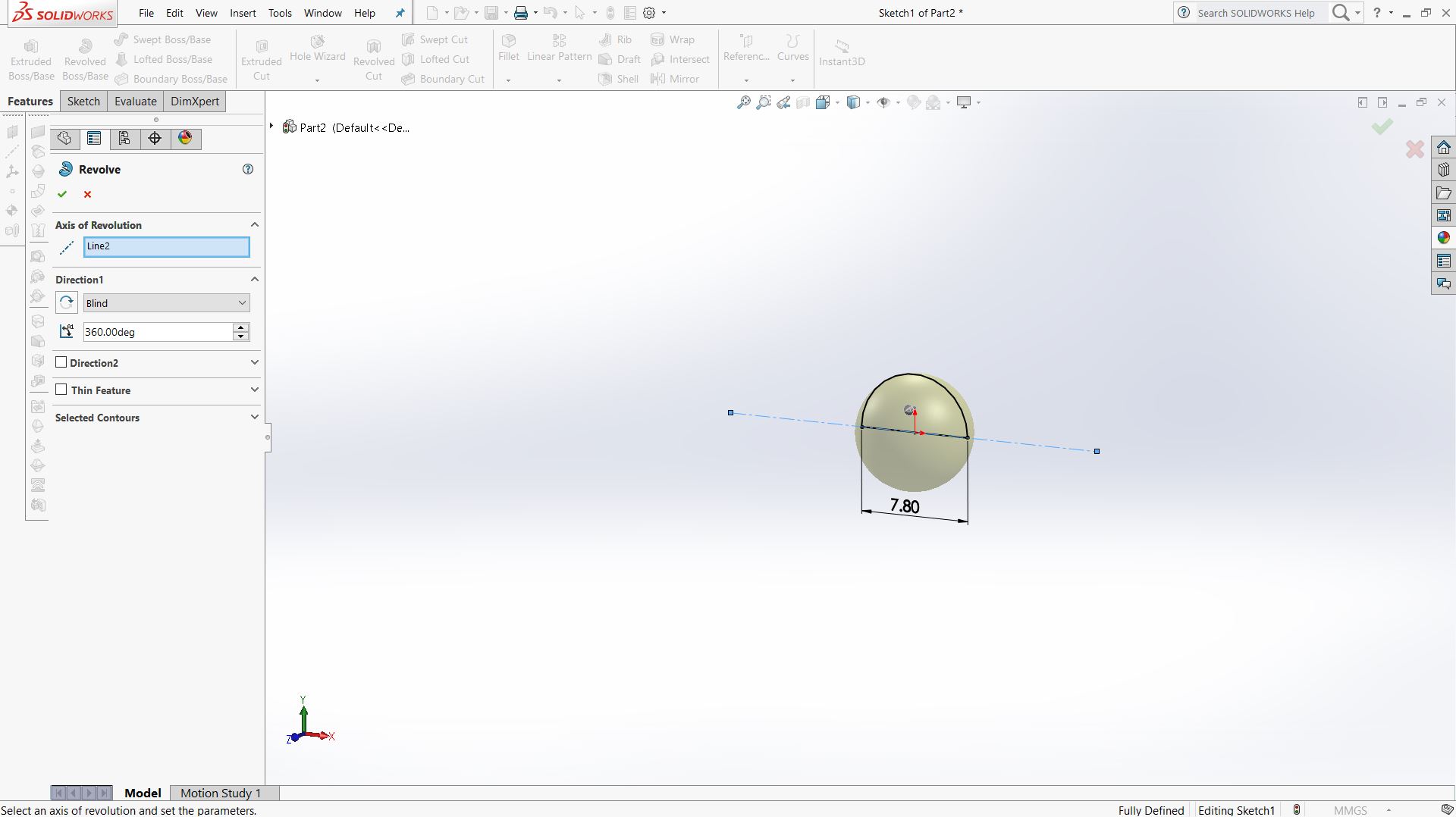
And the first part were ready.Next I made a simple sphere (using again the revolve feature)
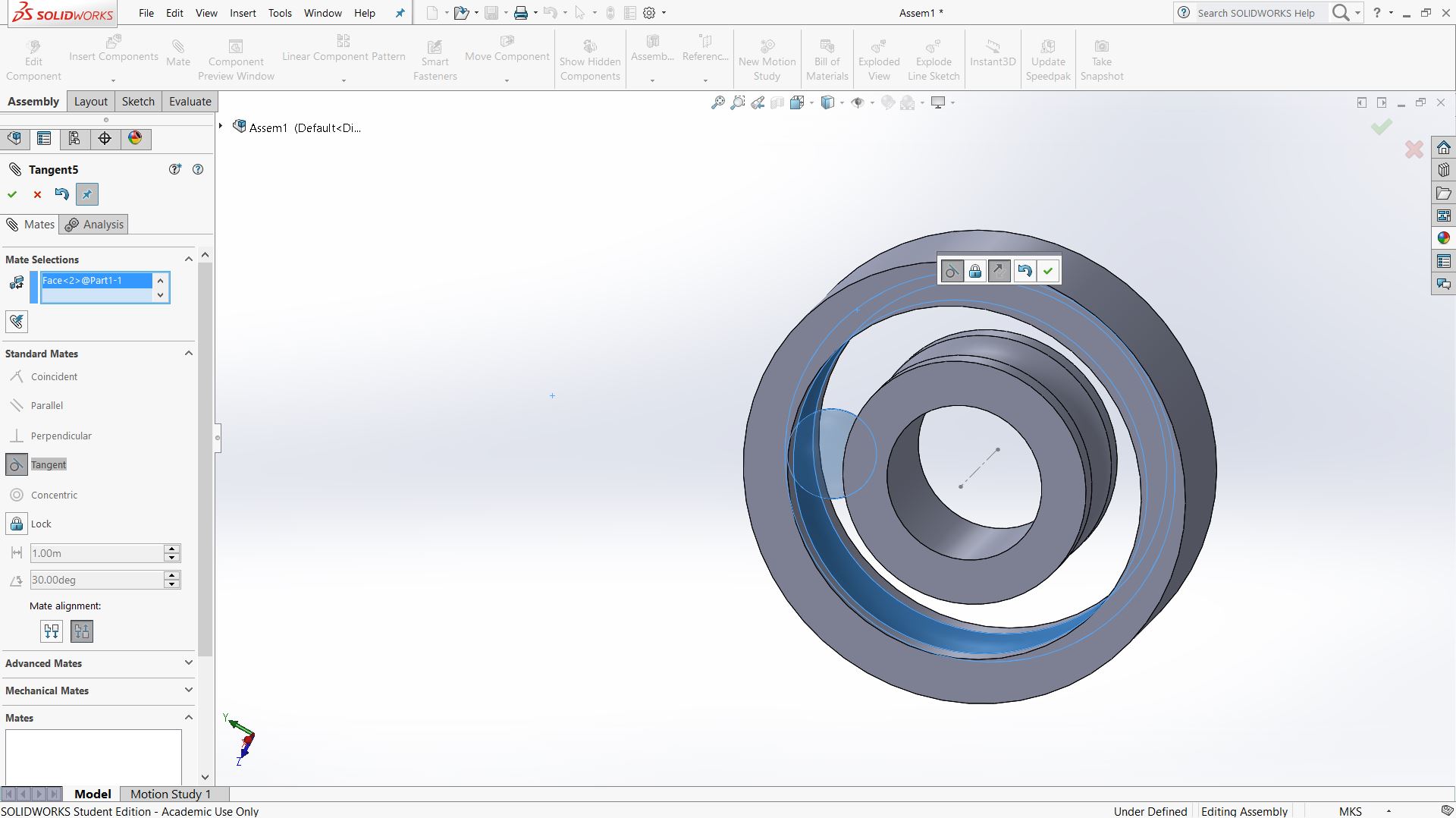
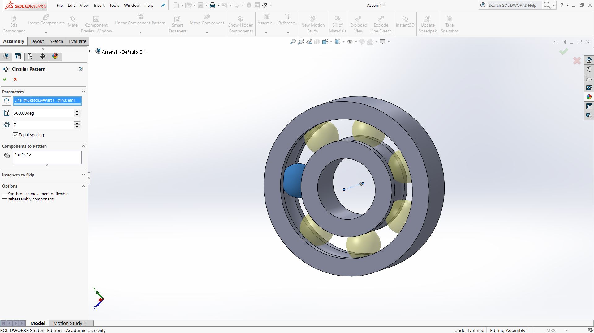
After that I assemble the ball bearing.I defined the relation between the ball and the cage whit the feature mates and then I used circular Pattern
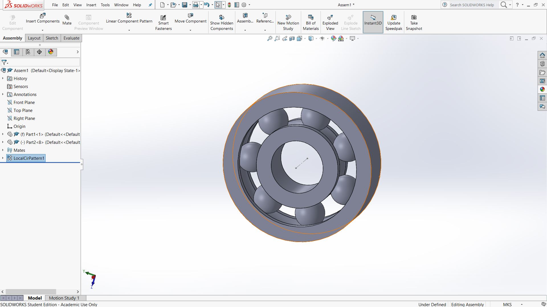
Final result:
End of the Update
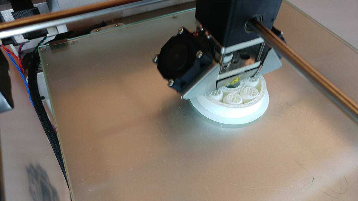
Then I saved the model in .stl and I opened it whit Ultimaker Cura in order to produce the gcode for the Ultimaker 2,the 3D printer that the istructor allowed us to use.
Hold the left button to zoom the images
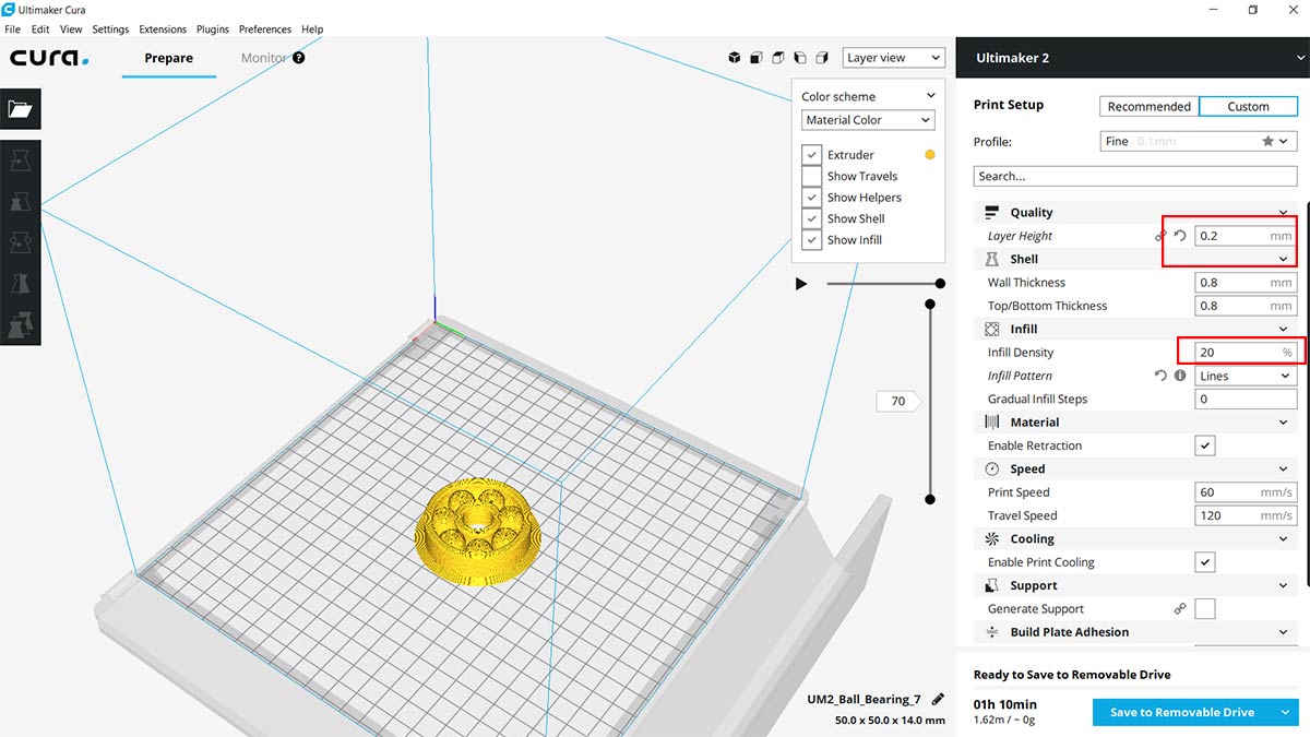
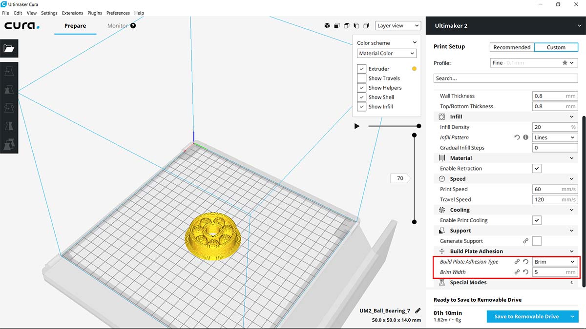
As shown in the images I selected the profile ''Fine'' and I changed :
In the middle of the print I had a problem :
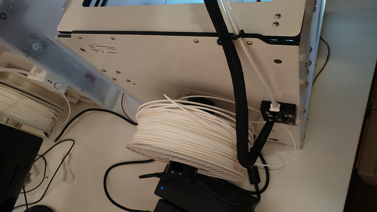
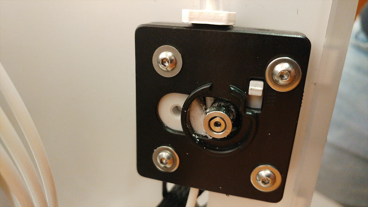
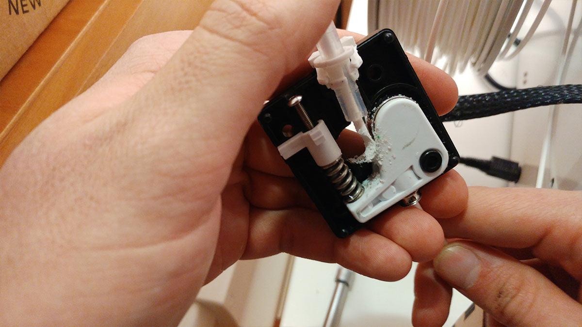
And whit the help of Dario Bernabini we fixed it .
We cutted the damaged material, we cleaned the motor's shaft and removed the dust. Than we pulled away the filament remaining in the bowden tube. After that we repositioned the bowden tube inside the feeder and we put it back on the engine. For our one, the correct position is with "CE" logo on top, but it is not said that it applies to everyone. Try to see the spinning direction of the motor and see in which position it is better to be placed. Remember to turn off the 3D printer
I cleaned the Build Plate and resumed the print and this time everything went well.
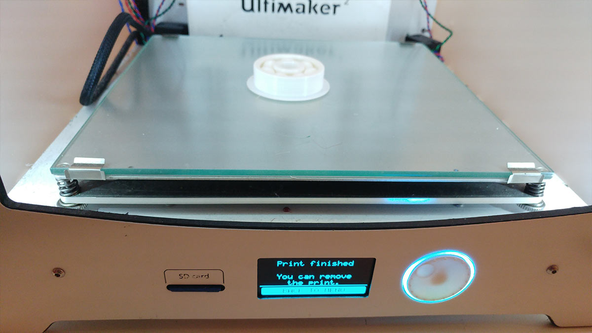
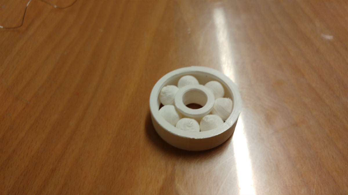
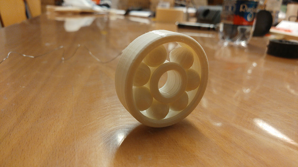
Here is the final results :
Conclusion
I didn't think that the 3D printing process needed so much settings and attenctions.First of all the materials.In our group assignment we used the same materials of different colors, and whit the same settings the results are completely different.Every roll of material needs to be tested and you need to find the perfect settings for every roll you want to use.Even the temperature of the room that host the 3D printer is a parameter that must be considered.3D Scanning
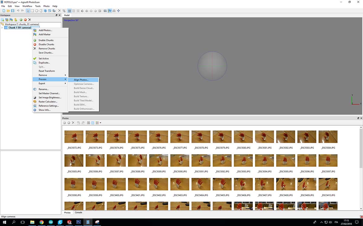
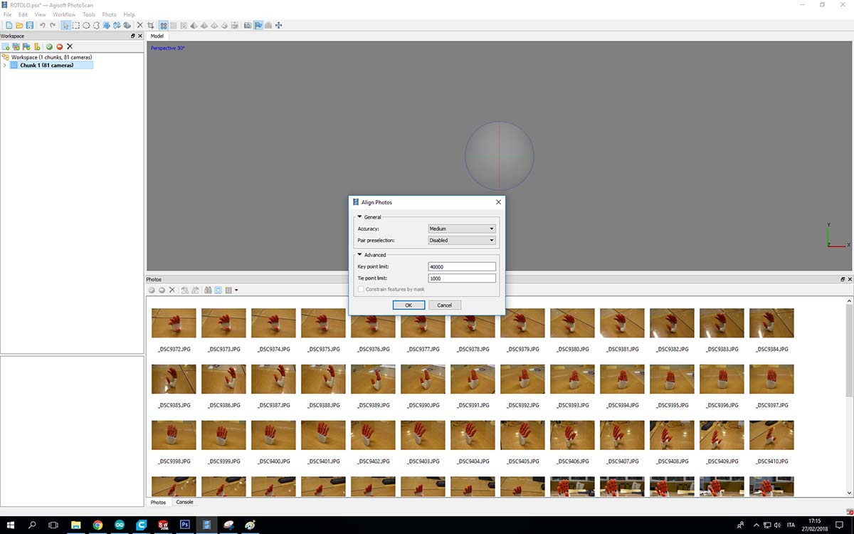
I choosed to scan a 3D printed hand that I found in our lab.To make the photos I used a Nikon D7200 and for the software I used Agisoft PhotoScan.To understand how Agisoft PhotoScan works is usefull to see this playlist of tutorials.I took pictures of the subject at 360 degrees and from two different heights,for a total of 81 shots(maybe too many).Then I imported them into PhotoScan and I started the workflow :Align Photos :
And a first problem occur :
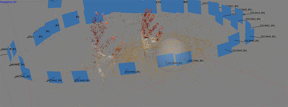
It recognised two different hands.I had to make the software understand that was a single hand. In order to do that I marked two point of the hand in many different photos and it worked :
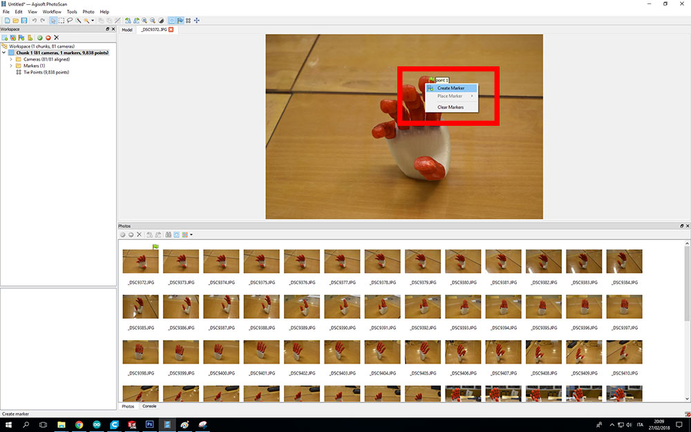
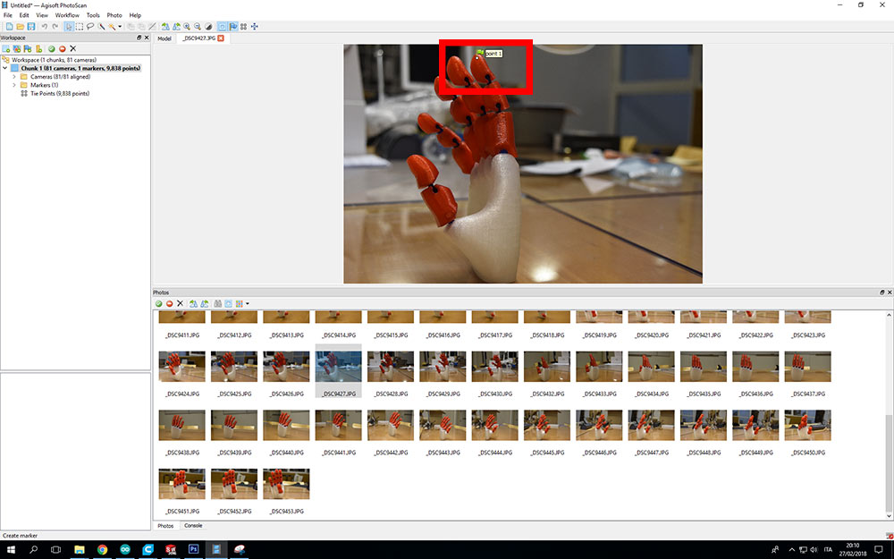
The marker is usefull to make the software knows that a point ( seen from a different point of view ) is the same in many different photos.PhotoScan could have problem to recognize that and you can help putting some markers.
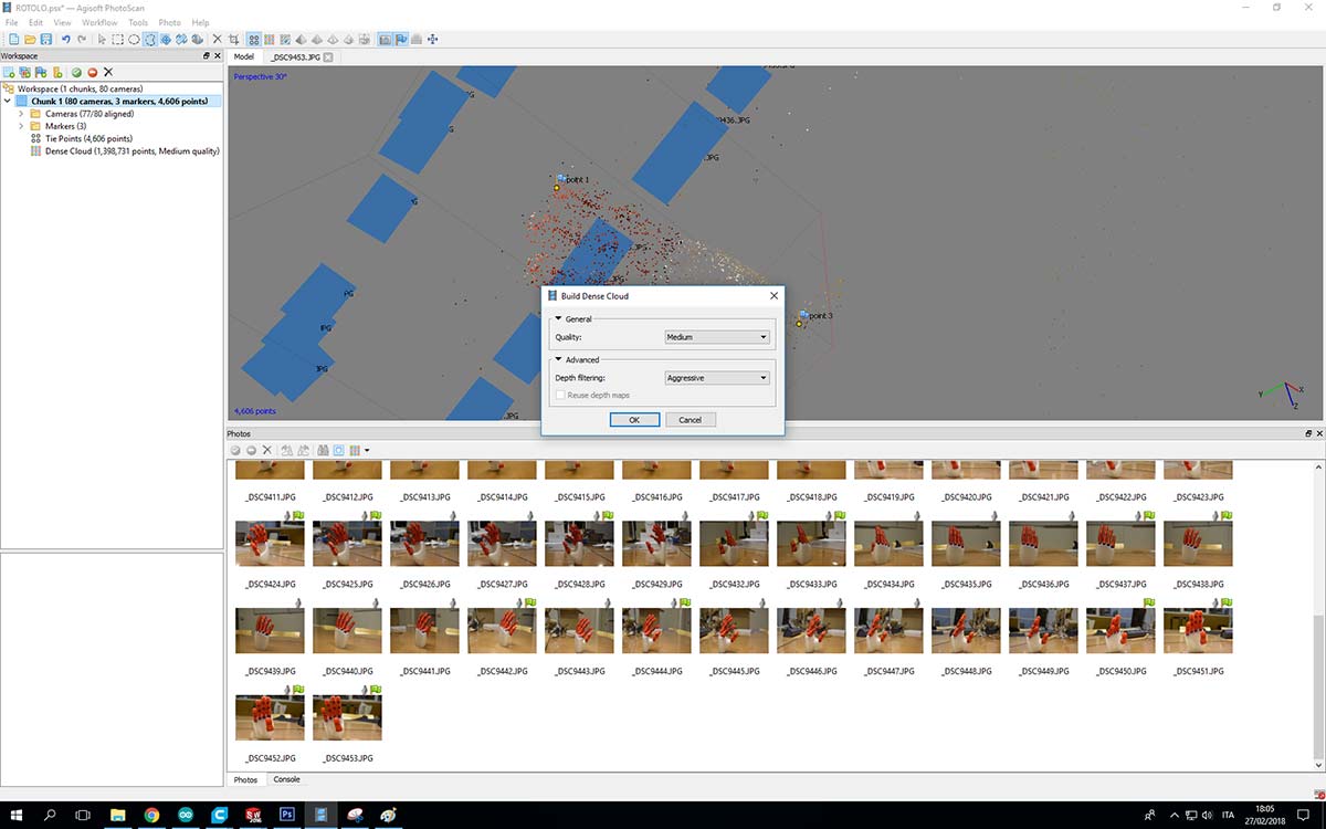
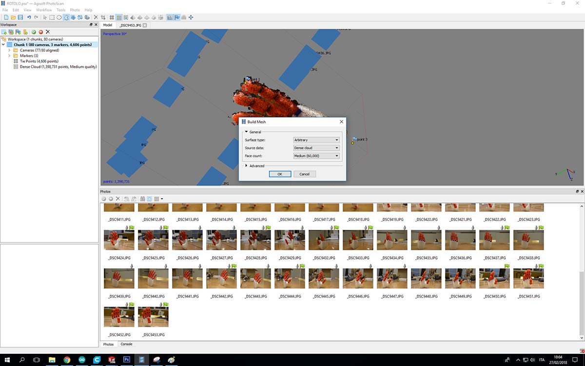
Once i fixed this problem I continued the workflow as shown in the photos:
the results :
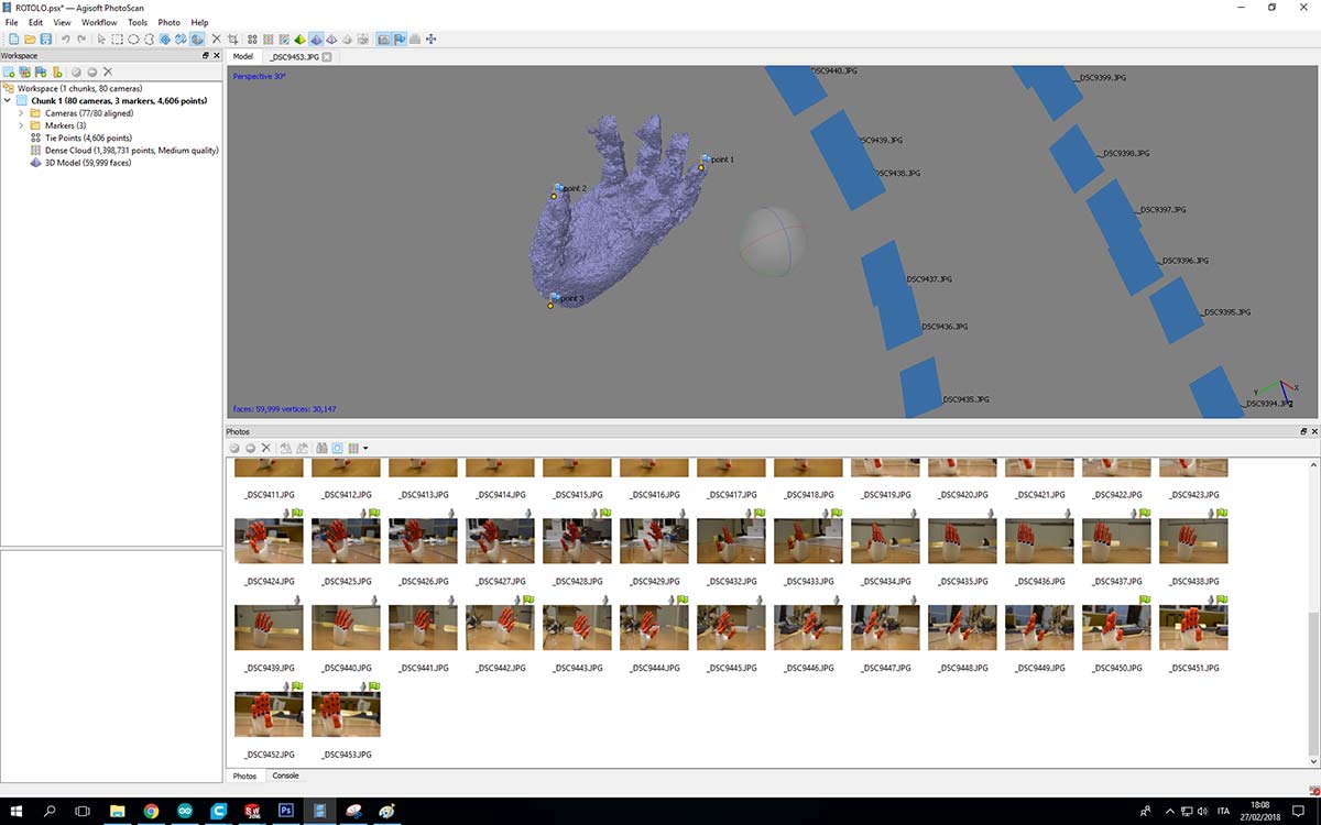
I'm not very happy about the results,I think that the amount of the photos I took cold had effected the final results
