electronic design.
this week assignements are:
- group project: Use the test equipment in your lab to observe the operation of a microcontroller circuit board
- Redraw the echo hello-world board, add (at least) a button and LED (with current-limiting resistor),
- check the design rules, make it (if you have time this week, test it).
Open eagle and install a library
This week i install Eagle,
i already had some experience on designing pcb on Fritzing, but it was really less efficient compare to Eagle.
So after install the software i had to "install" the library.
it's not really an installation, more a copy pasting the Fab.lbr on the good folder on my computer.
the good place on Windows is ..\EAGLE 8.6.3\lbr\ltspice
when the file was copied in this folder i started Eagle.exe. when the software was started, i had to create a new project
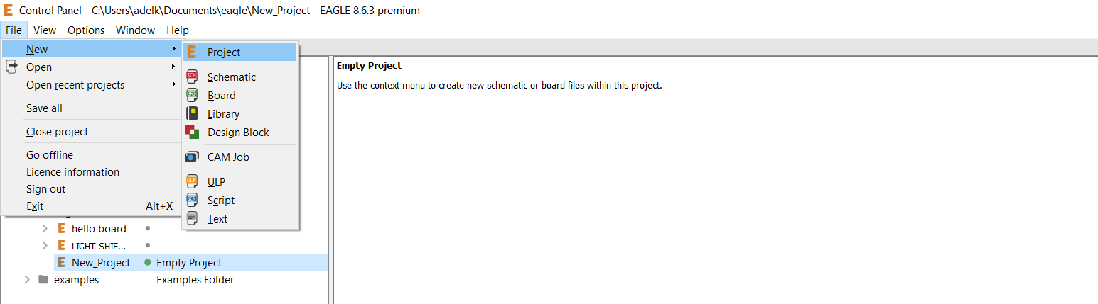 when you create (and named) you new project the first step is to create a scheamatic about it.
Same place but different button,
when you create (and named) you new project the first step is to create a scheamatic about it.
Same place but different button,new> Schematic when you did it open it on double clicking on it.
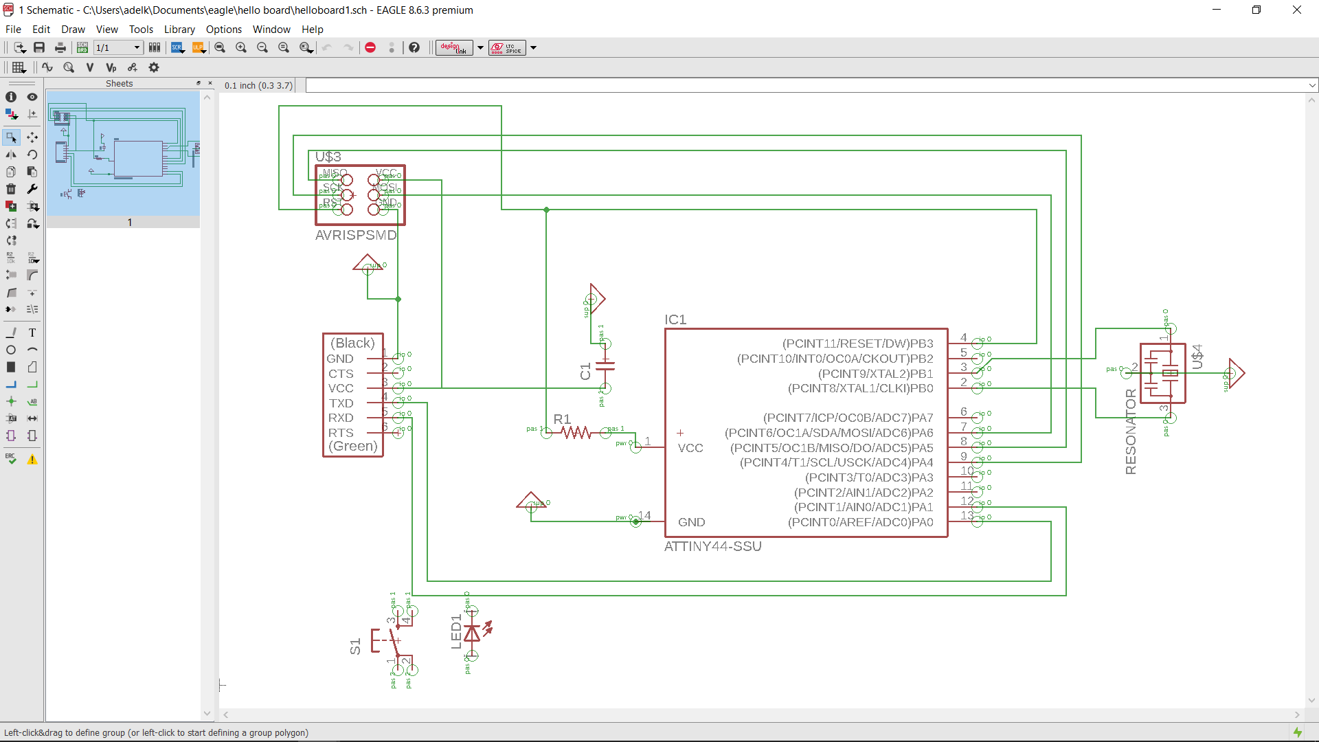
Make a scheamatic.
above you can see my schematics. for making that you need to
ADD your component
for adding component it's pretty simple just clic on add. there you'll find a list of component exisiting on eagle. and particulary you'll find the library you installed earlier!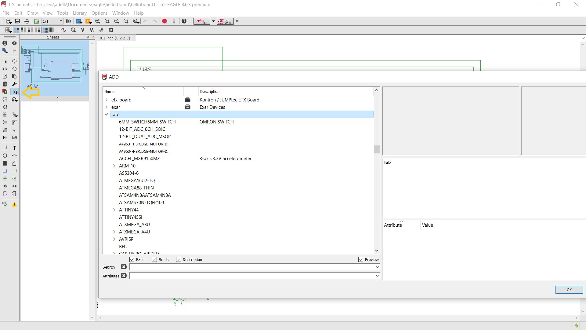 then i checked on the linked give by neil on his lectures of this week-(but accuatly sending you ower to the week 8 (embeded programming)) here i found the list of component i need to implement.
- 1 X Attiny45
- 1 X resonator 20MhZ (NOT A Chrystal!)
- 1 X Capacitor 1uF
- 1 X led
- 3 X resistor 499, 10K, 10K
- 1 X Button 6mm
 now you have to link every pin you want to connect together .
the best way to do it for the first step is to look on the documentation of neil sent. you'll have a board design with named of component wehere component is connected to what, it will make your life simpler.
for simplify you schematics do not hesitate to use some GND component or VCC, it will make it clear when you'll tried to read it.
now you have to link every pin you want to connect together .
the best way to do it for the first step is to look on the documentation of neil sent. you'll have a board design with named of component wehere component is connected to what, it will make your life simpler.
for simplify you schematics do not hesitate to use some GND component or VCC, it will make it clear when you'll tried to read it.
Make your board.
This part you have to go on File>new>board.
there you'll see all the component with lot of Yellow link between them.
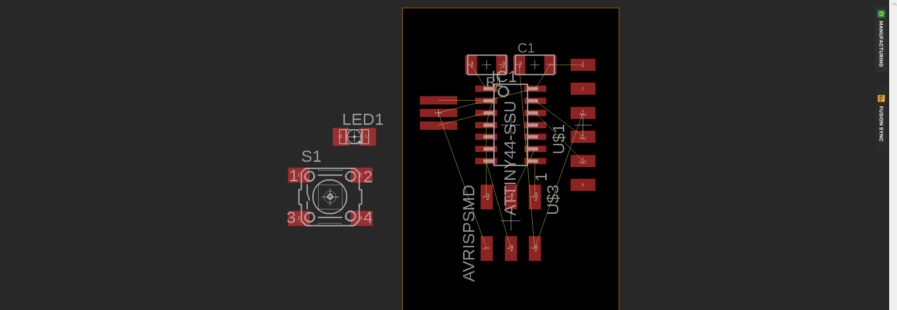 so you have to move the component and place them the more efficient as possible.
 you have to tried to have less as possible yellow line crossing each other. when you did that you can start to route the component by hand.
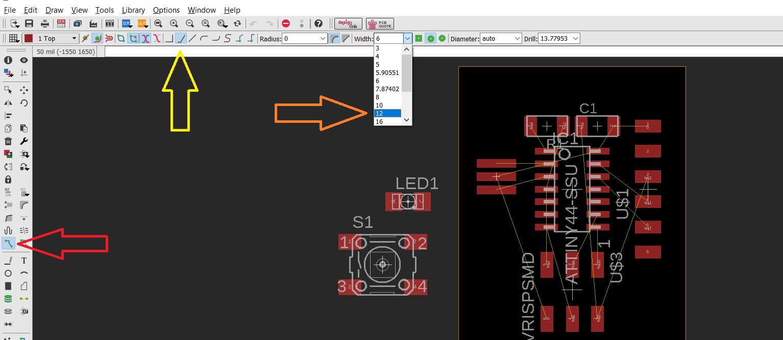
- Red Arrow, this is the routing tool, it make you able to route manually all the pad they need to be connected together.
- yellow arrow, type of line, it's the best way to make them for me, it's avoid the 90 degres angle.
- Orange arrow, this is the size of the path, less than 12 look really thin, i'm not sure it's really good idea to go less than that.
- Engraving (png file)
- Cutout (png file)
- Eagle Schematics (sch file)
- Eagle board (brd file)
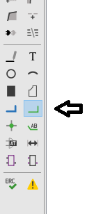
cutout line
for making the cutout line is pretty simple, you have to choose the Milling layer (red Arrow), then you have to create a polygon around your board5yellow Arrow), with the form you want.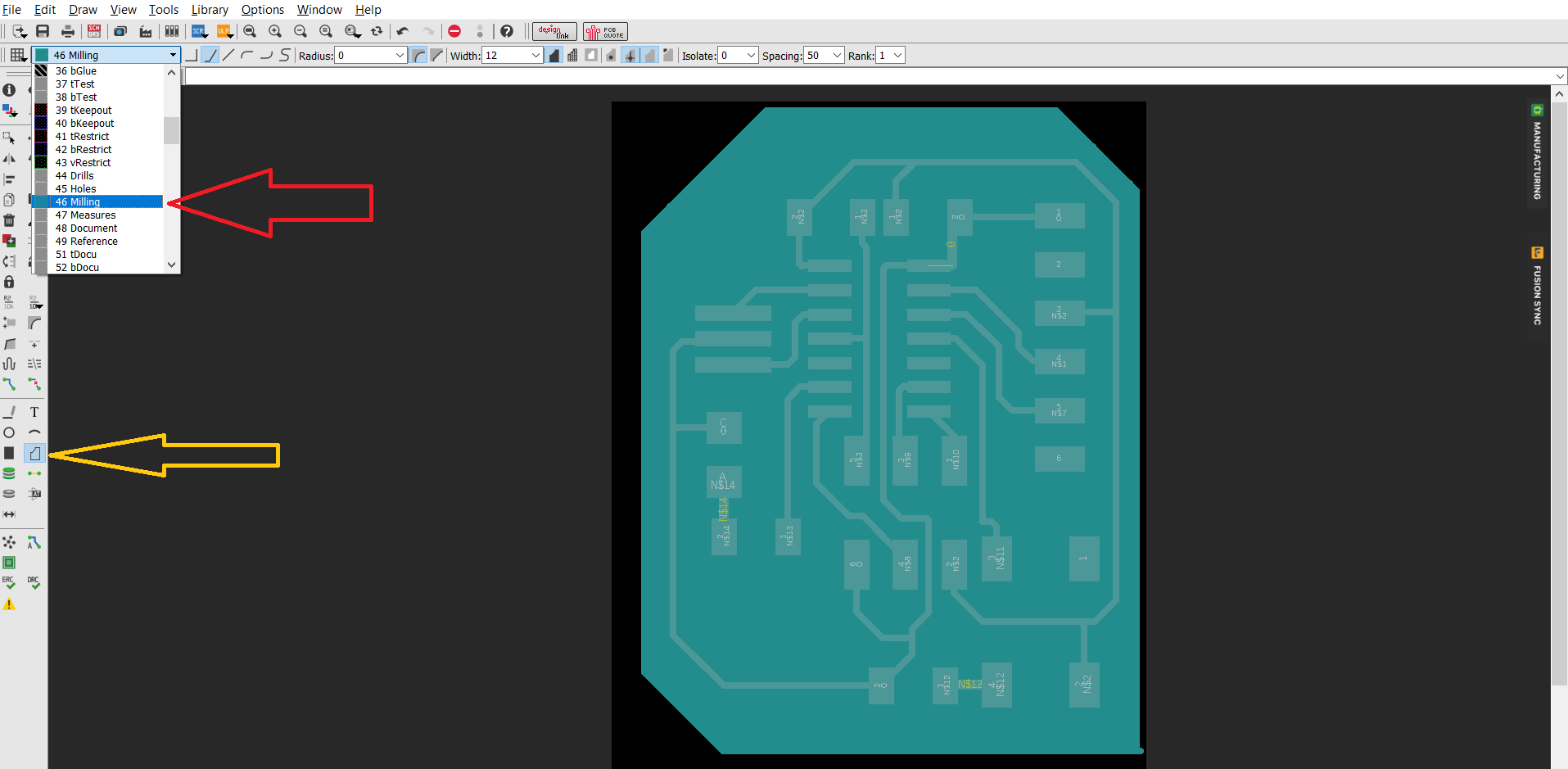 when you did that is time to export your files.
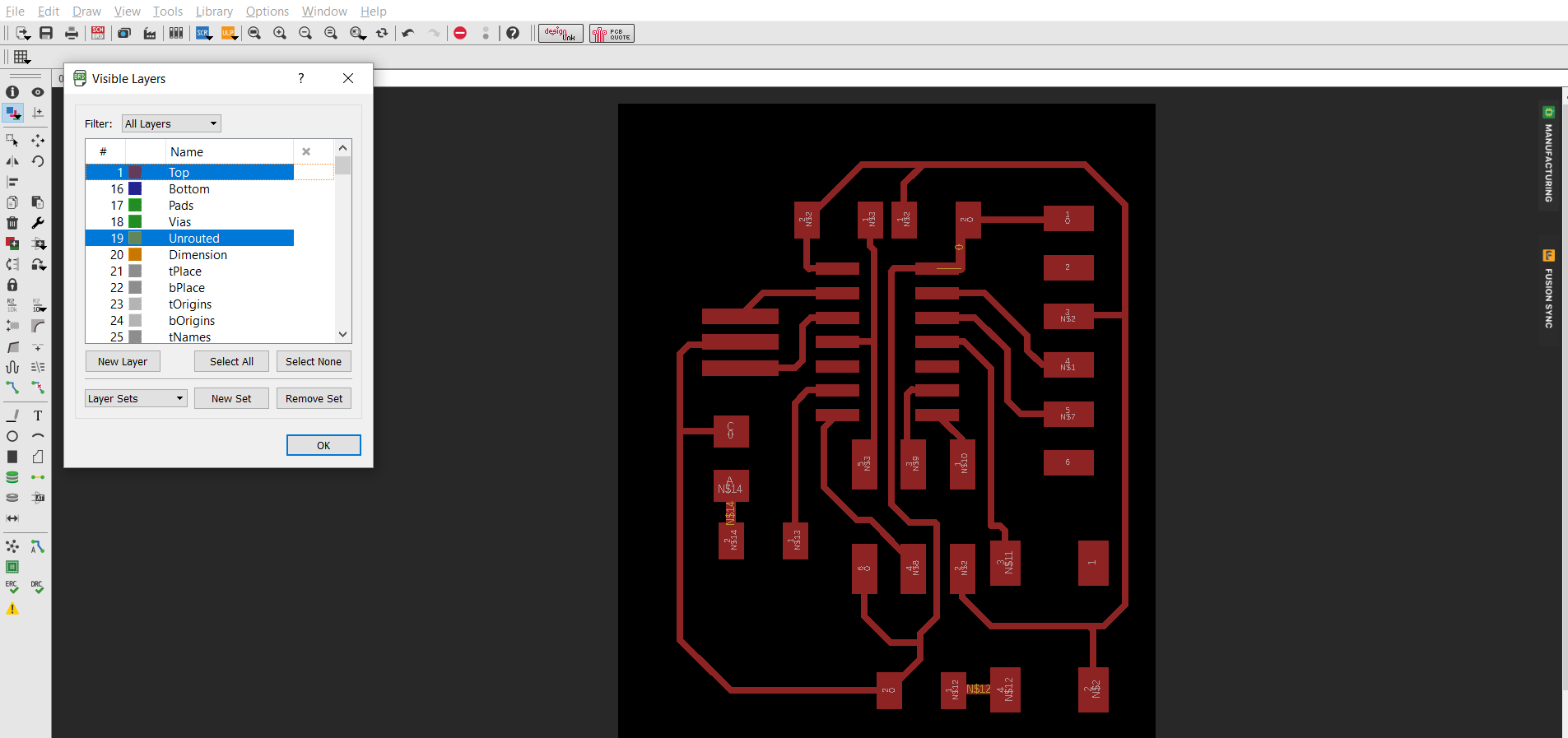
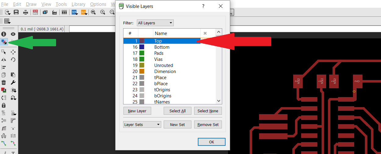
select the top layer only
when you did that is time to export your files.
select the top layer only
 do not forget to add some resolution on your design(brown arrow). 1000 dpi look great on fabmodules.
do not forget to make it on monochrome. it will make you a file without text, route and pads on white else in black.
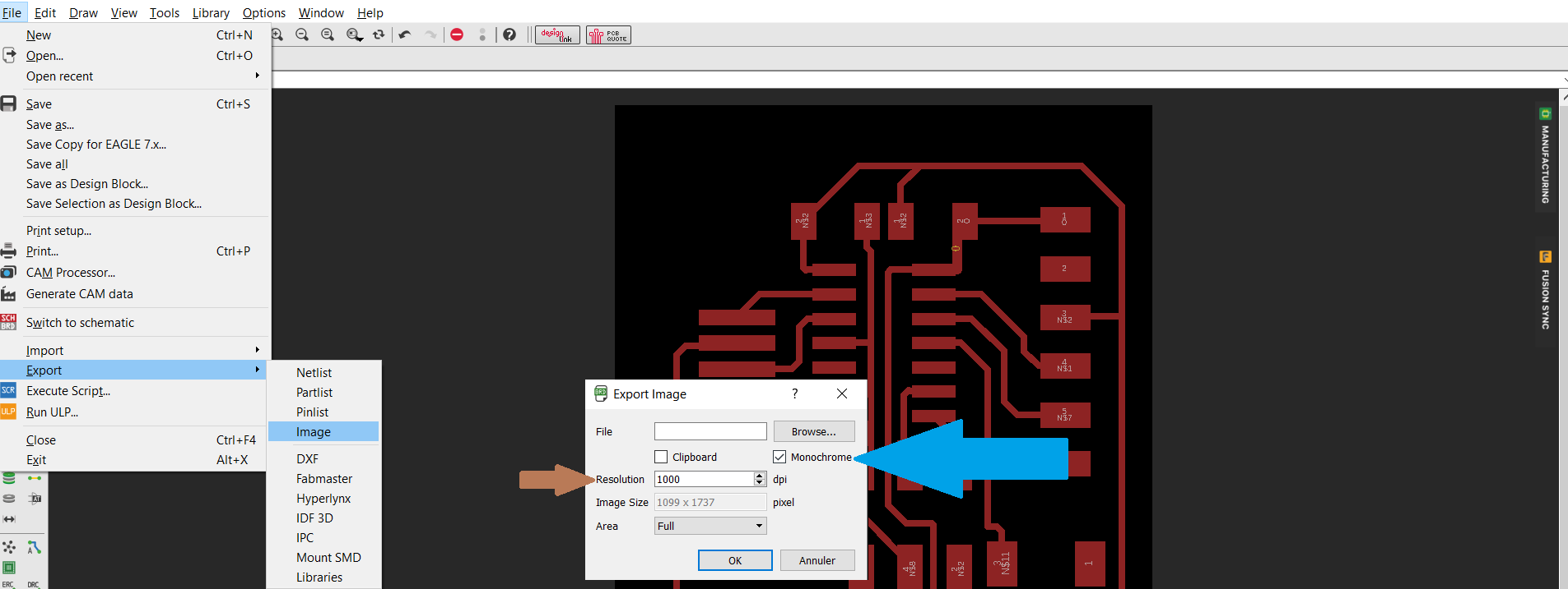 make the same with the milling layer too.
Mill, Cut, Solder.
well for the rest is pretty straight forward. two weeks ago i explained how to make a pcb with png file.
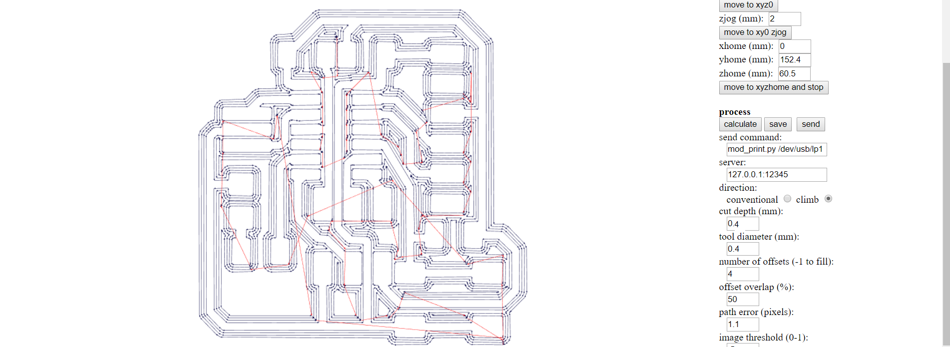
we make some fabmodule GCODE for the srm20
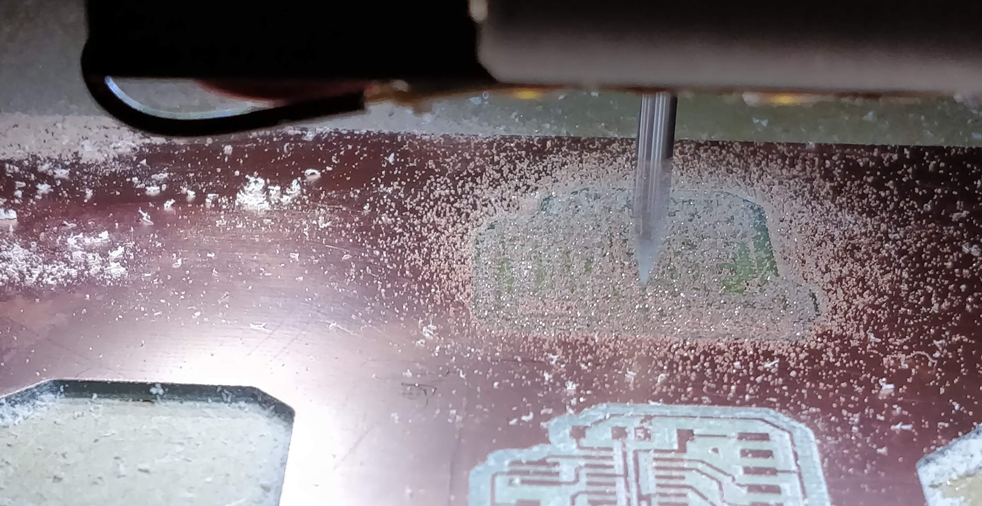
 We engrave the board
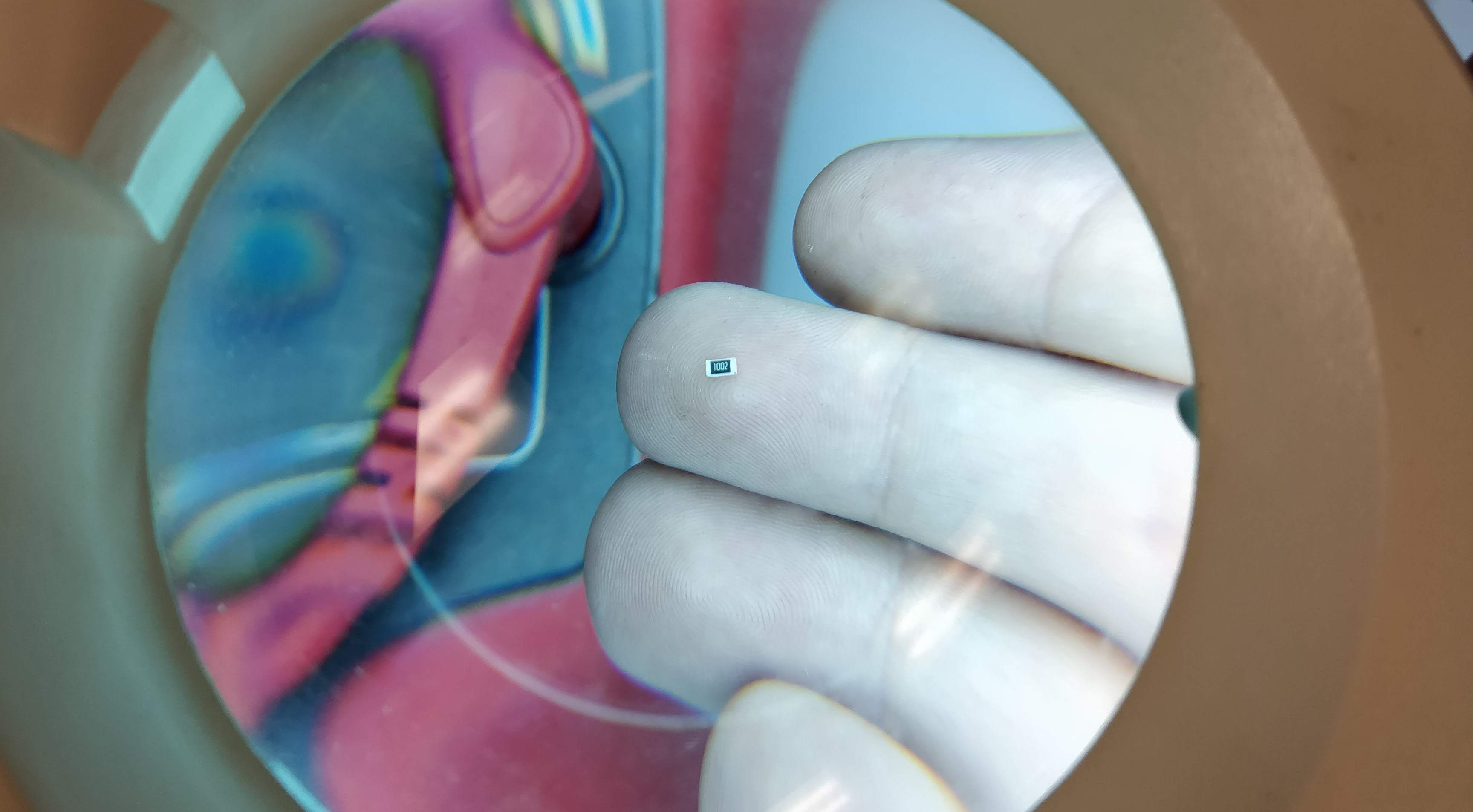
 we solder some 1206 resistor
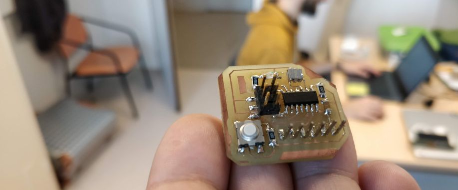
 And VOILAA!
Troubleshooting
A bit confuse about this week, we had to make a design of a pcb with button and a led but with no info on wich output of the Attiny we need to be connected so i checked the code of Embbeded programming for looking on wich pinout is the good one. but not sure if it was the good way to do it.-
What i've learned
I learned to make my own pcb on a software more evolve than fritzing. i already played with eagle couple years ago. but never i made a pcb this quick --
file of the week.
here you'll find the file of the week
For downloading
right click and save as