16. Machine Design
This week we continued to work on the rotational caster . As part of this I improved the design of the central chamber, created a connection piece and made a small pcb board for the encoder.
Improved Chamber
There were concerns that my the original design of the chamber might be structurally weak. I decided to look again at creating a box with formed walls and used a tutorial to make chamber with slightly overhanging roof and flooring.
I worked in different axis to create a the left and front sketches, extruding the walls to a thickness of 3mm. I used the mirror command to duplicate bodies to make new walls. The dimensions of the box was 150 x 100 x100 and all were entered parametrically.
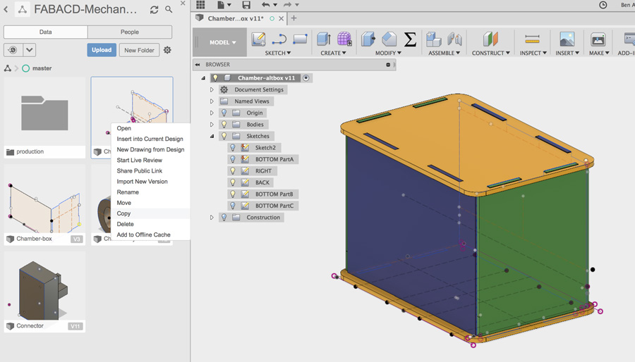
The perspective view in Fusion 360 served as a useful reference for reverting to 2D lasercutted pieces. Before converting sketches (for left, front, top, etc) into dxf files, I made a copy of the file to a new folder named 'production'. This was a useful tip from Adel, to use the copy to clean the file of any lines/construction lines before exporting. This greatly reduced the work to be done in Inkscape. The final step was to convert the line work to RGB red, 1px and cut with the Trotec lasercutter.
Because we were using plywood, it is necessary to look for the natural curve in the wood and place the sheet curve-side up. Masking tape is applied to all corners - possibly the whole perimeter – to make sure the sheet is flat. The final piece assembled with a much tighter fit and no need for glue.
Connector Piece
The original idea with the chamber was that it would be attached to the axis with a set of gripping forks. The considered the dimensions of such as system and how to ensure a firm hold, I decided to go with a simpler structure.
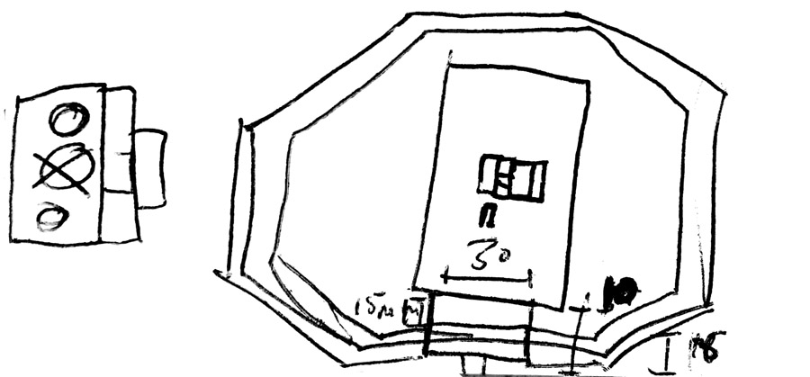
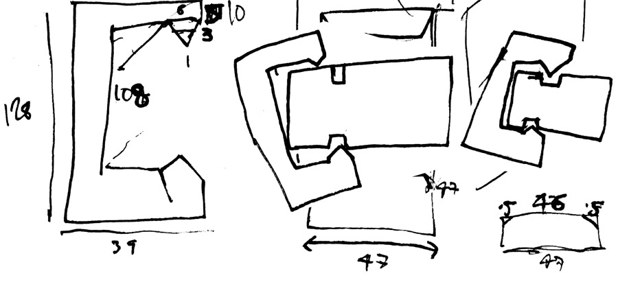
I measured the dimensions based on the thickness of the axis joints and gap between the axis and box. I considered spacing for screw holes and height for the screw-head.
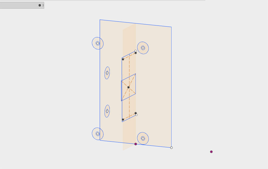
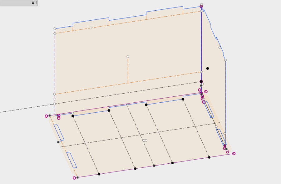
I have learnt that knowing which direction to extrude your sketch is key to returning to a file, should changes be required. If you get it wrong, you have to move the sketch in a different axis, and this can be quite messy, as seen in the view above.
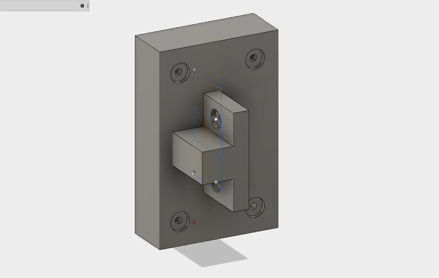
One of the challenges of the design was working on different axis – I made several mistakes positioning the right-angle on the rectangle. When I printed the piece for the second time, I discovered the gap was bigger than I had measure previously. I therefore returned to Fusion and extruded the object further.
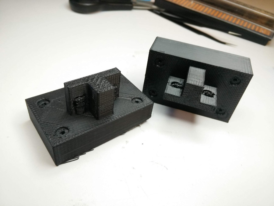
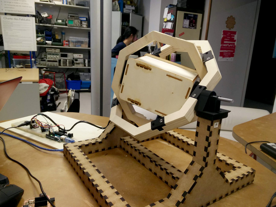
Finally, I tested the position of the new chamber and connectors on the machine. This would later be screwed in position.

Encoder Board (Eagle, FabModules)
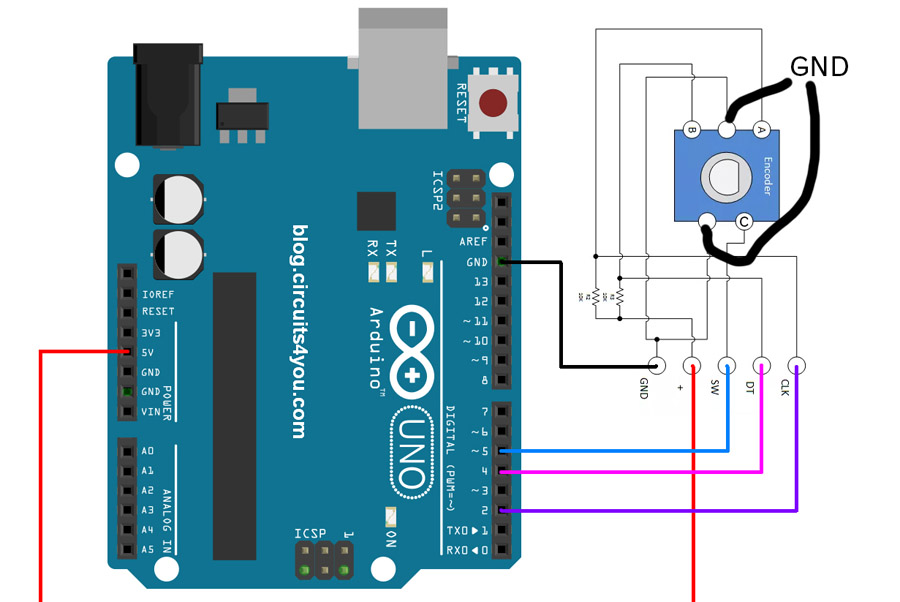
A pcb board to carry out the separate task of running the encoder was required. We reviewed a similar Arduino sketch with wiring for an encoder dial. Our encoder would be much simpler, without resistors.
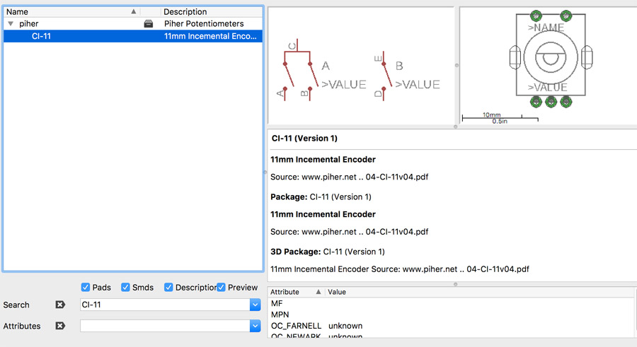
Initially I PC16SV encoder but discovered issues later when soldering the board. On the repeat board, I selected a similar encoder (CI-11) with 5 pins, and made sure it matched in terms of dimension by switching the board view and comparing the width of the five pin pads (it was similar, so a match for the project).
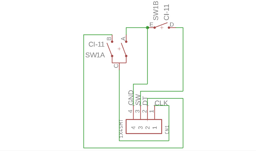
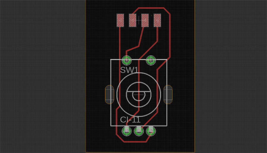
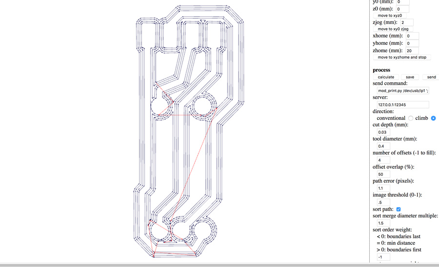
Using the net tool I attached the relevant components, naming them with connections to GND, SW, DT and CLK. VCC was not required for this board. In board view, I routed the connections under the encoder in places and reviewed the position of holes that would be drilled. The dimensions were set to approximately 20 x 50mm. I exported the trace and cut files as pngs and worked in photoshop to convert the dimension rectangle to white.
In Fabmodules, there was some issues getting the cut file board to appear. I found that by widening the photoshop canvas by 25% (width and height) they appeared in Fabmodules.
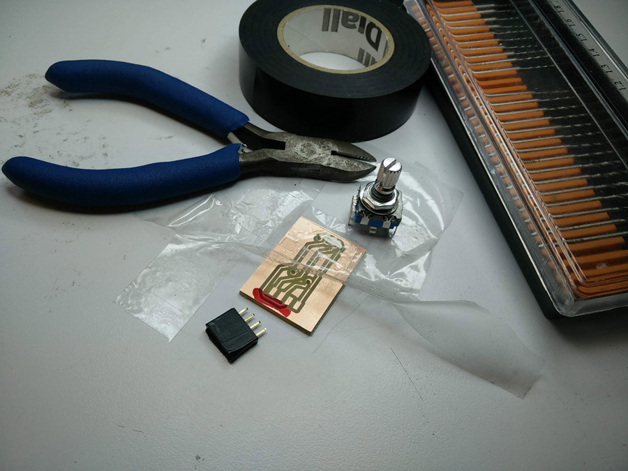
Encoder Board (SRM-20, Components, Soldering)
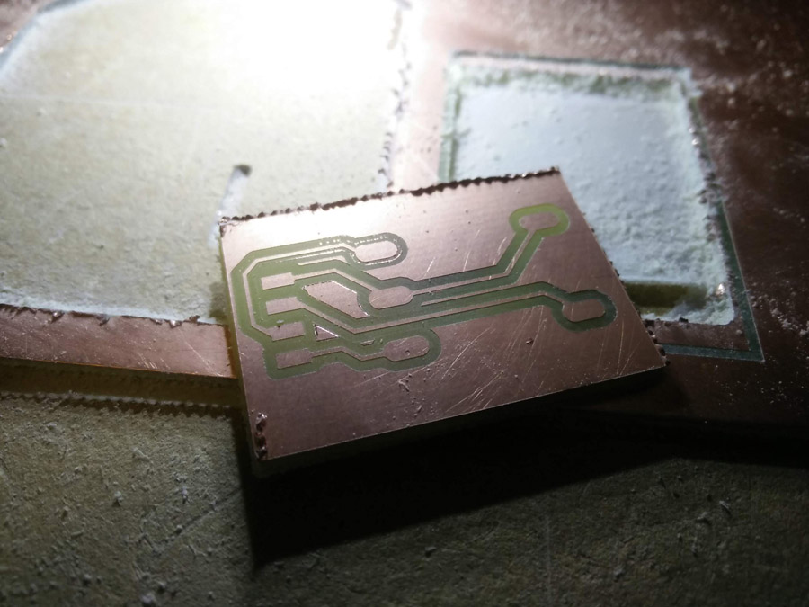
After calibrating my blades on the x/y/z axis, I cut the board successfully. There was some traces of copper but as I checked with the multimeter, there was none effecting routing to other pads. However, there was an issue with the distance between pads – The encoder did not match. I therefore returned Eagle and found an alternative.
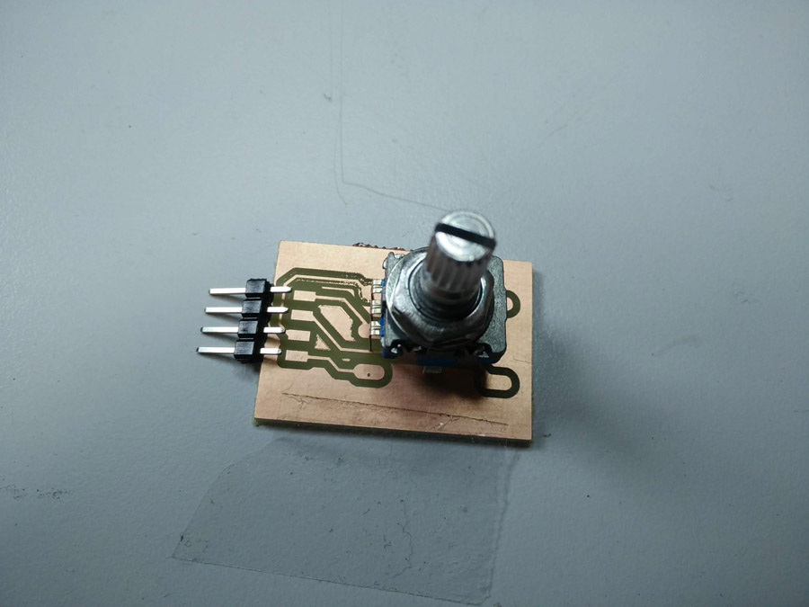
Above, showing an incorrect match.
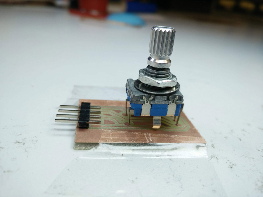
Above, showing a correct match. Seen here with 5 flat male pins that I would later swap for female-to-male.
Five flat pins were cut to the correct size and black electrical wire was strapped around it incase of damage. Because the pins were still exposed to routing below, I used nail varnish to cover the same part of the routing. When the varnish had dried, I soldered the five pin.
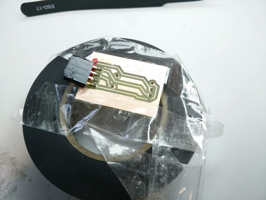
A roll of tape tape helped me achieve and I also found it a very handy for soldering in different directions – No need to unstick repeatedly from a work surface or release from a frame.
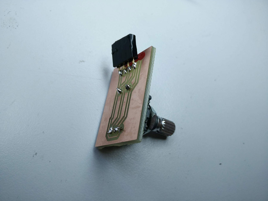
I used a Dremel drill with a very small head to down through the pcb. I used a pair of pliers to remove an additional piece of metal from the encoder base (as with the button in Embedded Programming). I then push the encoder pins through the board from upside-down and soldered it from the top.