Programs on input device board
Because, I am not in Paris, I didn't have an easy access to multimeter or other control devices.
So, I made different programs to control my board and see if all work right before making my final program.
Led test
/*
* input device
* led test : just blink twice a second
*/
const int ledPin = 8;
void setup() {
pinMode(ledPin, OUTPUT);
}
void loop() {
digitalWrite(ledPin, HIGH);
delay(500);
digitalWrite(ledPin, LOW);
delay(500);
}
Switch test
/*
* input device
* Switch test : turn the led on when switch button is pressed.
*/
const int ledPin = 8;
const int switchPin = 3;
int switchState = 0;
void setup() {
pinMode(ledPin, OUTPUT);
pinMode(switchPin,INPUT);
}
void loop() {
switchState = digitalRead(switchPin);
if (switchState) {
digitalWrite(ledPin, LOW);
} else {
digitalWrite(ledPin, HIGH);
}
}
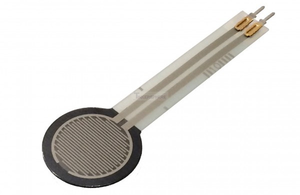
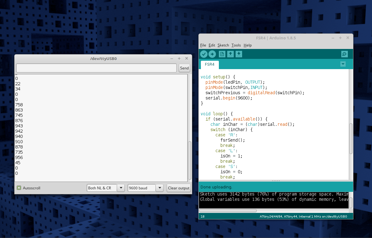
FSR test
/*
* input device
* fsr test : make the led blink faster when you press the FSR sensor.
*/
const int ledPin = 8;
const int fsrPin = 7;
void setup() {
pinMode(ledPin, OUTPUT);
}
void loop() {
int value = analogRead(fsrPin);
if (value==0) {
digitalWrite(ledPin,LOW);
} else {
value = map(value,0,1023,500,20);
digitalWrite(ledPin,HIGH);
delay(value);
digitalWrite(ledPin,LOW);
delay(value);
}
}