Week 12 : Output devices
- Add an output device to a microcontroller board you’ve designed and program it to do something
Fab Academy 2018 - Thierry Dassé
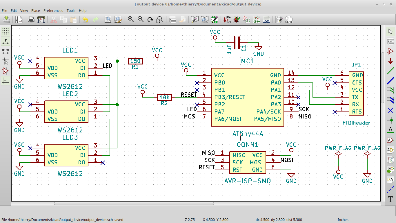
For my output device board, I decided to use WS2812 RGB led.
I first read the datasheet to know how to make my PCB and decided to
put three led on a bus.
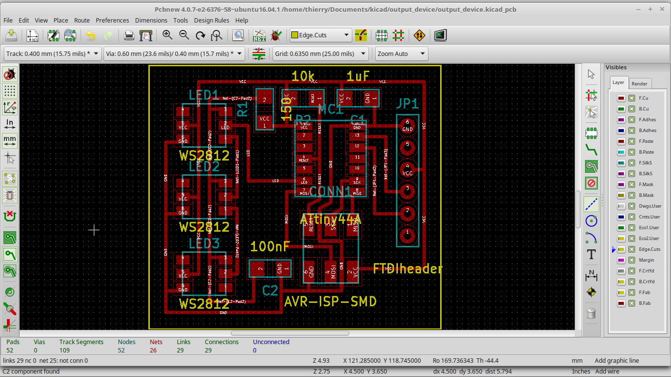
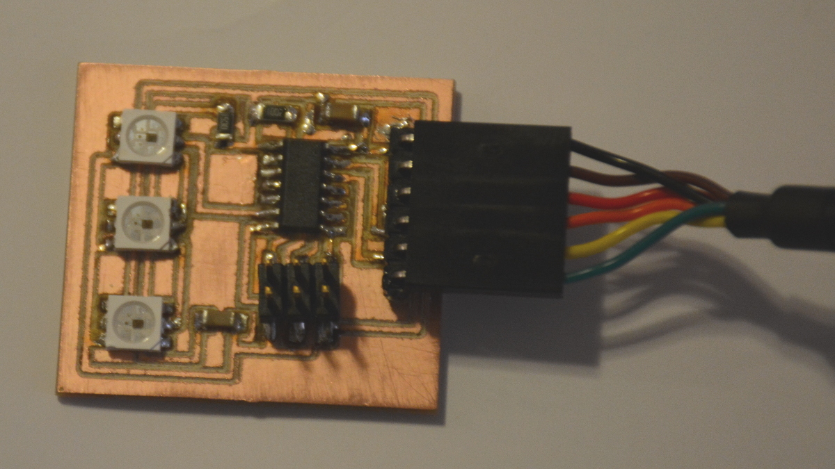
I first designed my board on Kicad and mill it on a DIY CNC. I made my gcode with FlatCam.
To test my board, I wrote some basic programs.
First one is a FTDI test. Program just sends back characters it receives.
/*
* FTDI test
* return serial datas
*/
#include<SoftwareSerial.h>
#define rxPin 0
#define txPin 1
SoftwareSerial serial(rxPin,txPin);
void setup() {
serial.begin(9600);
}
void loop() {
if (serial.available()) {
char inChar = (char)serial.read();
serial.print(inChar);
}
}
Second program is a simple red blink on first led.
/*
* WS2812 Blink
* should make first led blink in red each second using FastLed library.
*/
#include "FastLED.h"
#define NUM_LEDS 3
#define DATA_PIN 7
#define CLOCK_PIN 13
CRGB leds[NUM_LEDS];
void setup() {
FastLED.addLeds
}
void loop() {
leds[0] = CRGB::Red;
FastLED.show();
delay(500);
leds[0] = CRGB::Black;
FastLED.show();
delay(500);
}
My program didn't work. First led light in green but doesn't blink.
I tried to debug. There are many possibilities. First, my board conception
could be false. I also can have shorts or bad solderings. My program can
also have bugs. I also read that Fastled doesn't work on AtTiny.
After different search, I wasn't able to find what is really wrong and
decided to turn my output device board to standard RGB Led. I will study
WS2812 Led later when I'll have more time to do it.
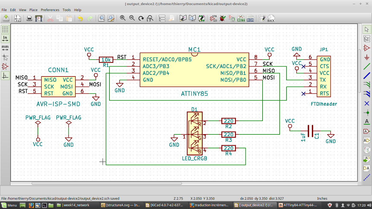
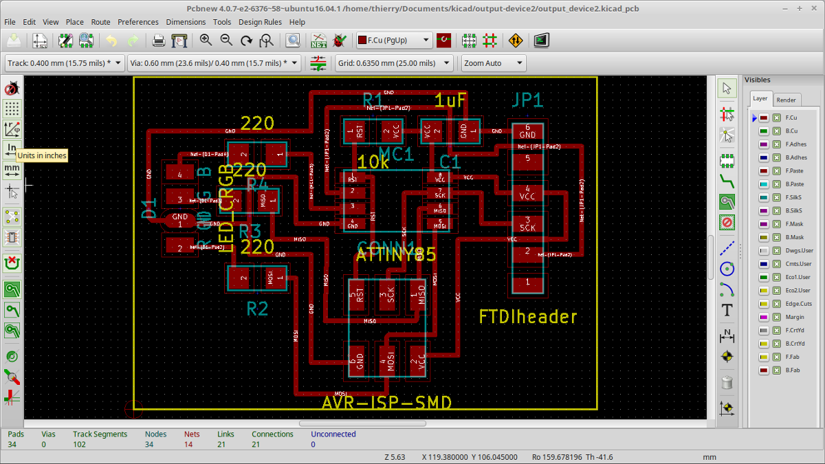
I designed another board with a simple RGB led ( I want to control from computer
sending hexadecimal color RRGGBB format.
Before all, I made test on a breadboard to know if I can control each color with PWM using ATTiny85.
After tries, I found PWM can be available on PB0, PB1 and PB4.
As PB0 and PB1 are same pins than MOSI and MISO, RGB led will blink while uploading but it doesn't matter.
At the contrary, I have not to use those pins for FTDI communication. PB2 and PB3 stay available for RX and TX.
I designed my board on Kicad, mill it using Roland SRM20 and sold it.
Complete kicad files and PCB png files
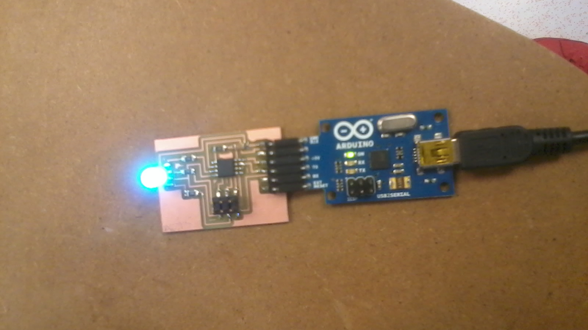
RGB24 program wait characters and transform a 6 characters string hexadecimal RRGGBB format to a 24 bit color on the led.
RGB led Color fade to new value by calculating weighted mean between old and new color :
(i×old_color + (16 - i)×new_color)/16 for i in [0..16]
In 17 steps, led move from old color to new one.
/*
* Output device
* RGB Led on ATTiny85
* send 24 bits color from serial FTDI in hexadecimal
* examples :
* 000000 black
* FF0000 red
* 0000FF blue
* 00FFFF cyan
* 2840A0
* ...
*/
#include
#define rxPin 2
#define txPin 3
char command[8]; // string to store characters from computer
short pos= 0; // position in string
int pin[3] = {0,1,4}; // RGB pins : pin 0 for red, pin 1 for green and pin 2 for blue
int current[3] = {0,0,0}; //curent color R:0, G:0, B:0
SoftwareSerial serial(rxPin,txPin);
void setup() {
for (short i = 0;i<3;i++) {
pinMode(pin[i],OUTPUT); //set each RGB pin to output
}
serial.begin(9600);
}
void light(char *color) { // fade led color to new one
int rgb[3];
for(int i = 0;i<3;i++) { //transform 6 character RRGGBB hexadecimal format to 3 integers
if (color[2*i]>57) {
rgb[i] = 16*(color[2*i]-55);
} else {
rgb[i] = 16*(color[2*i]-48);
}
if (color[2*i+1]>57) {
rgb[i] += color[2*i+1]-55;
} else {
rgb[i] += color[2*i+1]-48;
}
}
for (int i=0;i<=16;i++) { //fade current color to new color
for (int c=0;c<3;c++) {
analogWrite(pin[c],(int)((i*rgb[c]+(16-i)*current[c])/16));
delay(15);
}
}
for (int c=0;c<3;c++) { //copy new color to current
current[c]=rgb[c];
}
}
void loop() {
if (serial.available()) {
char c = (char)serial.read(); //read characters from serial FTDI
if (c == '\n') { //if a carriage return is received then change color
command[pos] = 0;
serial.println(command);
light(command);
pos = 0;
} else if (pos <=7){
command[pos++] = c;
}
}
}