Input Devices
Assignment
- Measure something: add a sensor to a microcontroller board that you have designed and read it
Files
PCB files
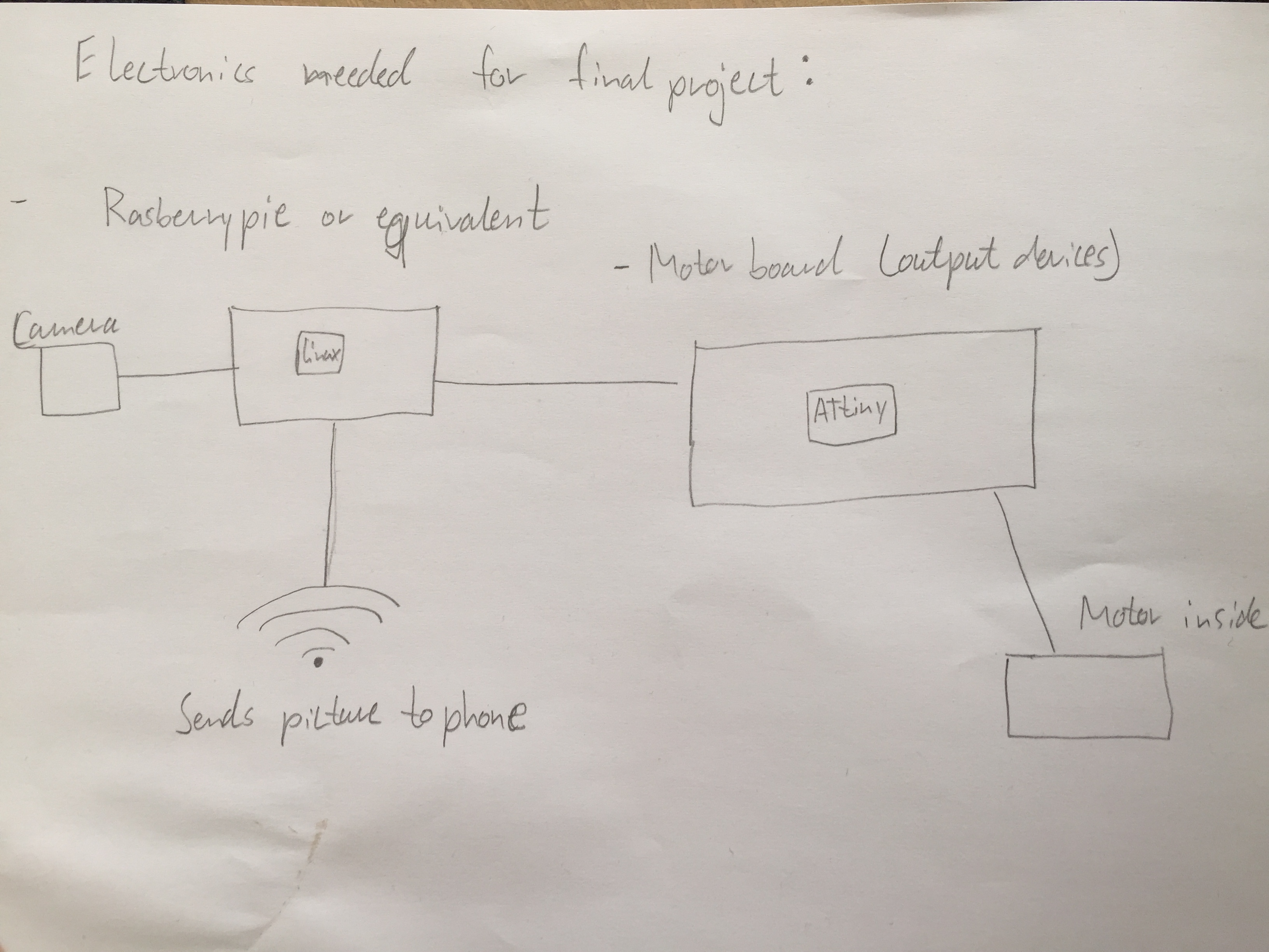
The first thing I thought about this week was how I should lay out all the electronics for my final project. For input devices I would need something that can handle a camera, process the pictures and send them to another device. This gets a little complicated and therefore Neil recommend getting a made circuit board to have enough power. My goal for this week (input devices) and the next week (output devices) is to get all the electronics worked out. I made a rough sketch showing all the parts that I needed.
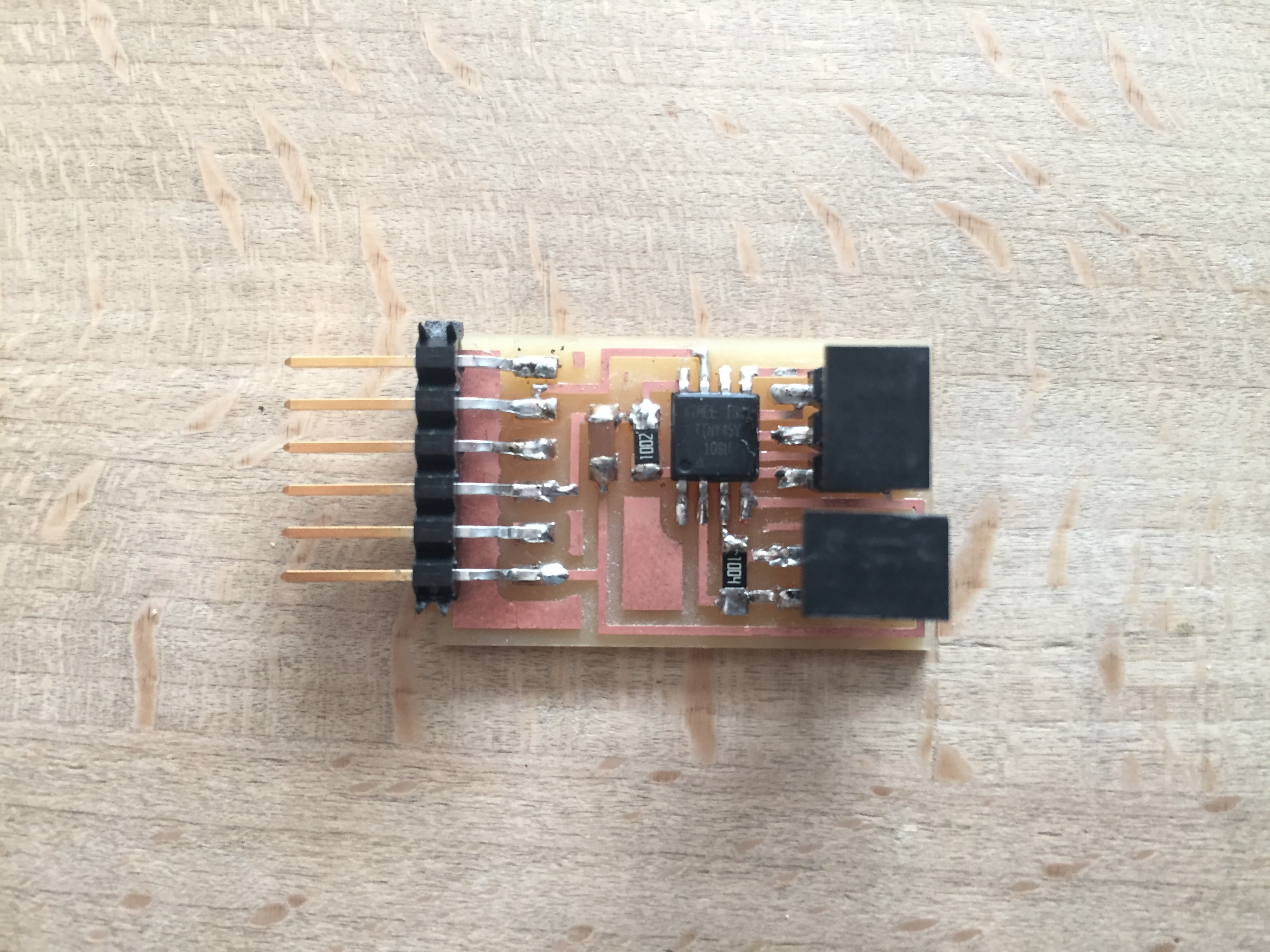
For the purpose of the week assignment I chose to make one of the boards Neil introduced in the lector, since I would not be making my own PCB for input devices regarding my final project. I made one that would be generating input with touch sensing.
I started by inserting the traces and outline files into fabmodules where I would not change the DPI setting since It was already set according to the job. This process is described in electronics production week (week 5).
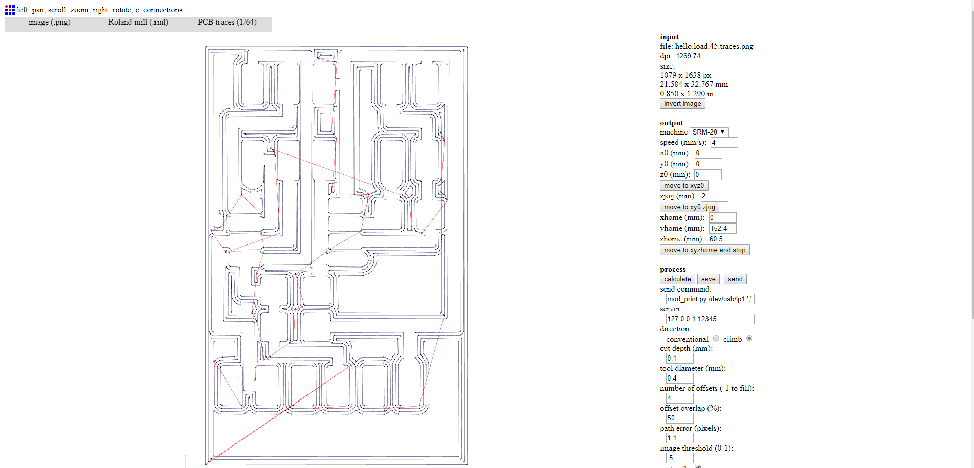
The milling was the best I had made in the program so far, of course this has a lot to do with the fact that I did not have to make any changes before milling, only adjusting fabmodules to our machine.
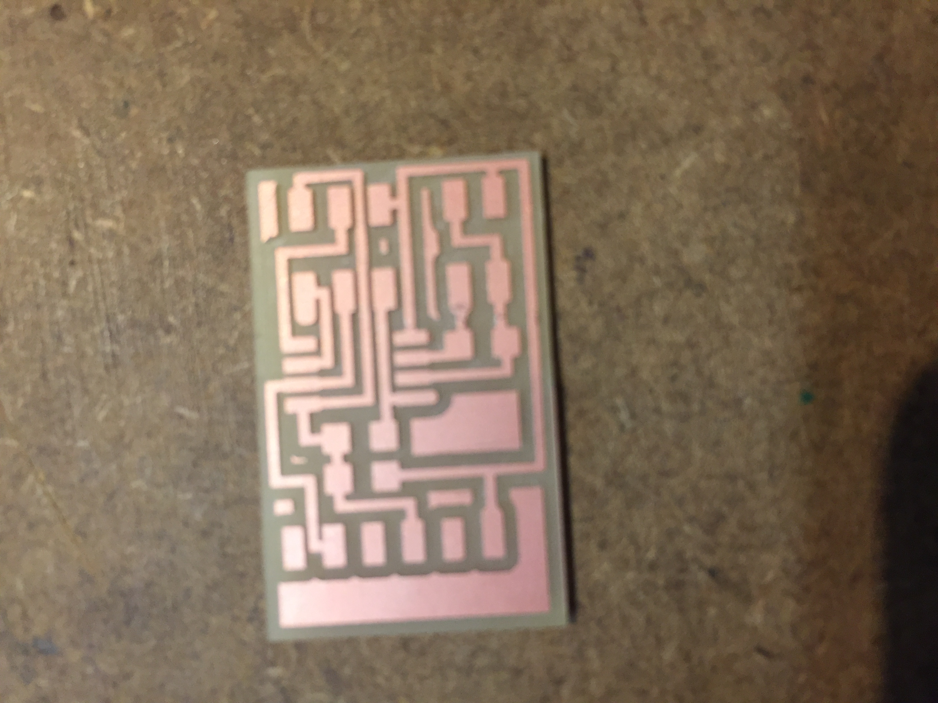
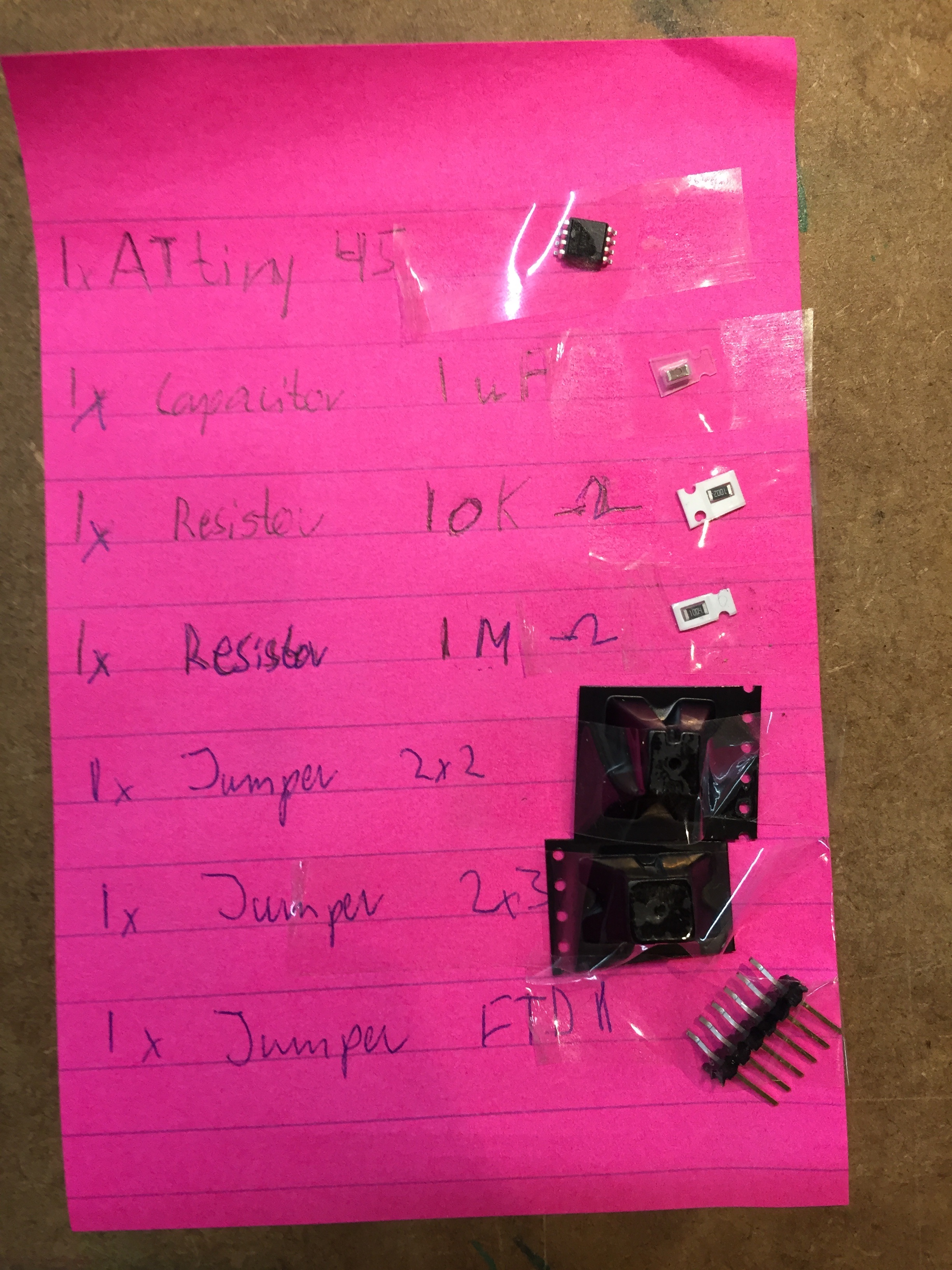
After that I found all of the components according to the picture of the traces with the components written on it.
Next I soldered the components which turned out quite well. Everything is getting increasingly shinier with the number of attempts I use at practicing my soldering.
Software
After I had produced the circuit board, It was time to make it work with software. In week 9 about embedded programming I had problems uploading c files with my own windows computer. This time I used a Linux (Ubuntu) computer we had in the lab instead. The software process as a whole was something we had some problems with, especially getting Python running, but our local instructor sorted it out and I replicated the process helping other people to get it under my skin.
Burning bootloader with the Arduino IDE and the ISP programmer is the first thing to do. this is documented in week 8.
I started by downloading the make file, the c file and the python file provided in this weeks lecture for this board. The next thing after that was to check if python was installed on the computer, which can all be done through the terminal, since it was the first time using python.
After that I uploaded the make file.
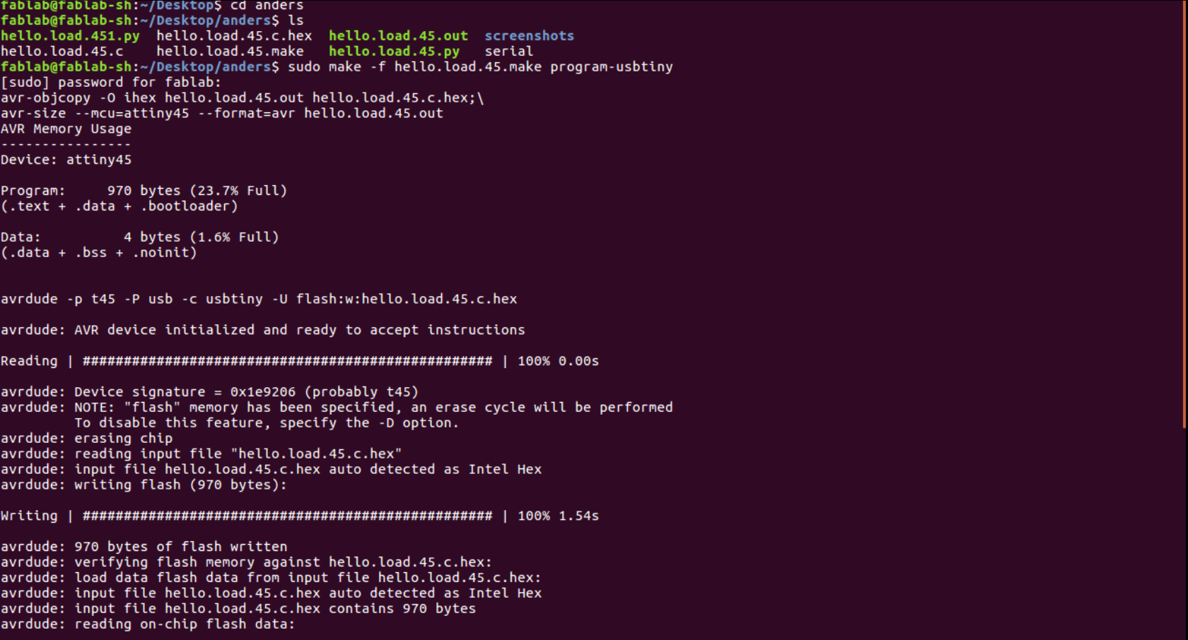
In Ubuntu the "sudo" command enables you to do things which is equivalent of administrator on a windows pc.
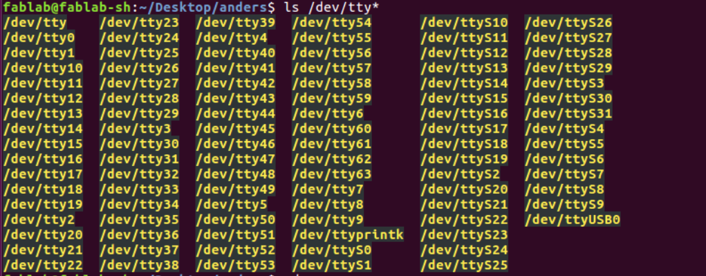
Next is to find out which USB port you would want run Python in. This was done by looking under devices.
The last step was to run the Python file while specifying the USB port.

If working correctly the Python interface will pop up.
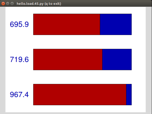
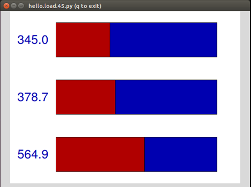
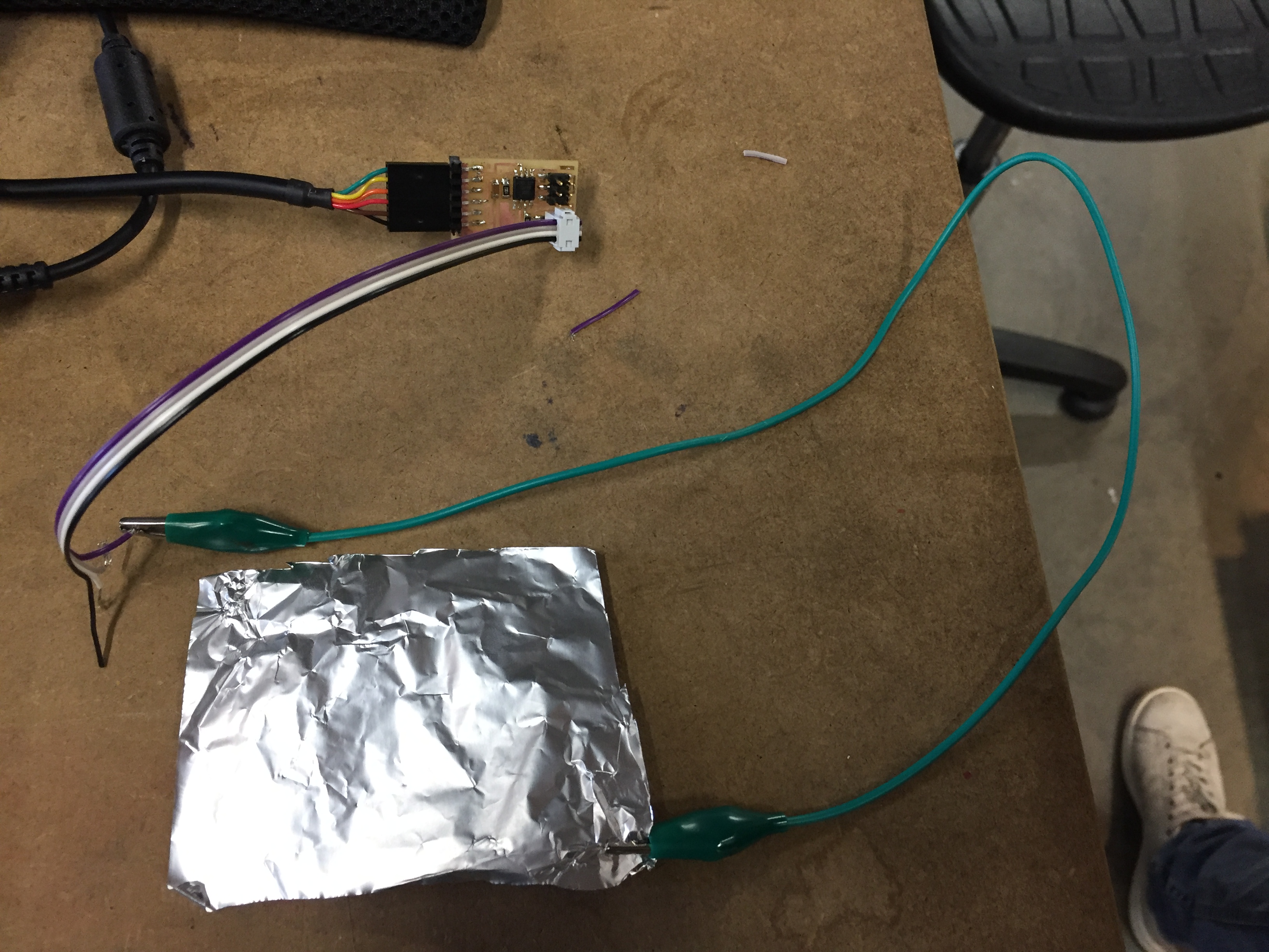
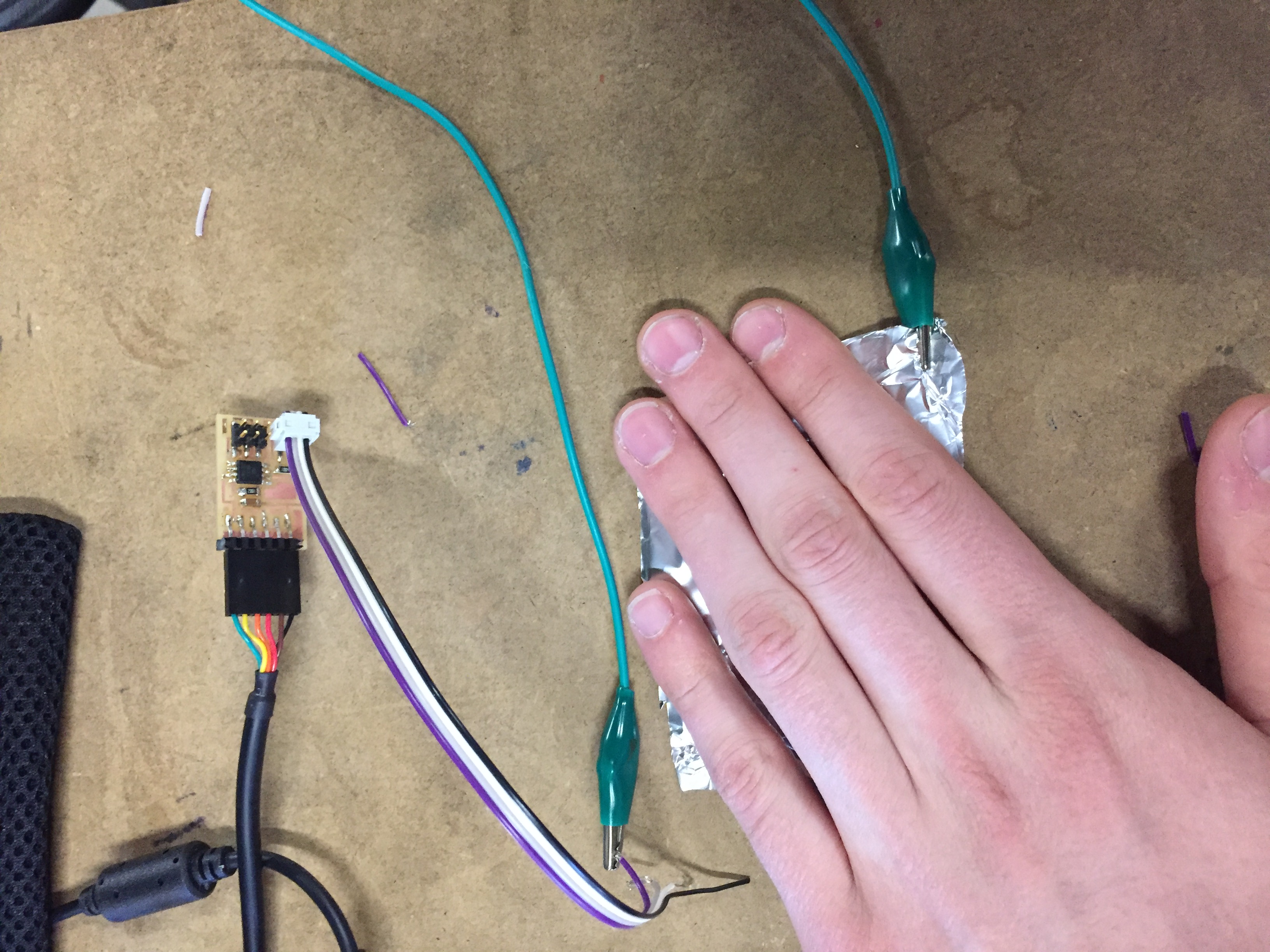
Using an input device
When using the made circuit board as an input device I attached wires to the the 2x2 pin jumper. One of the wires from the jumper (the one connected to "sense": see components figure ) I would to a piece of tin foil. The tin foil would then function as a touchpad, with the input showing in the Python interface:
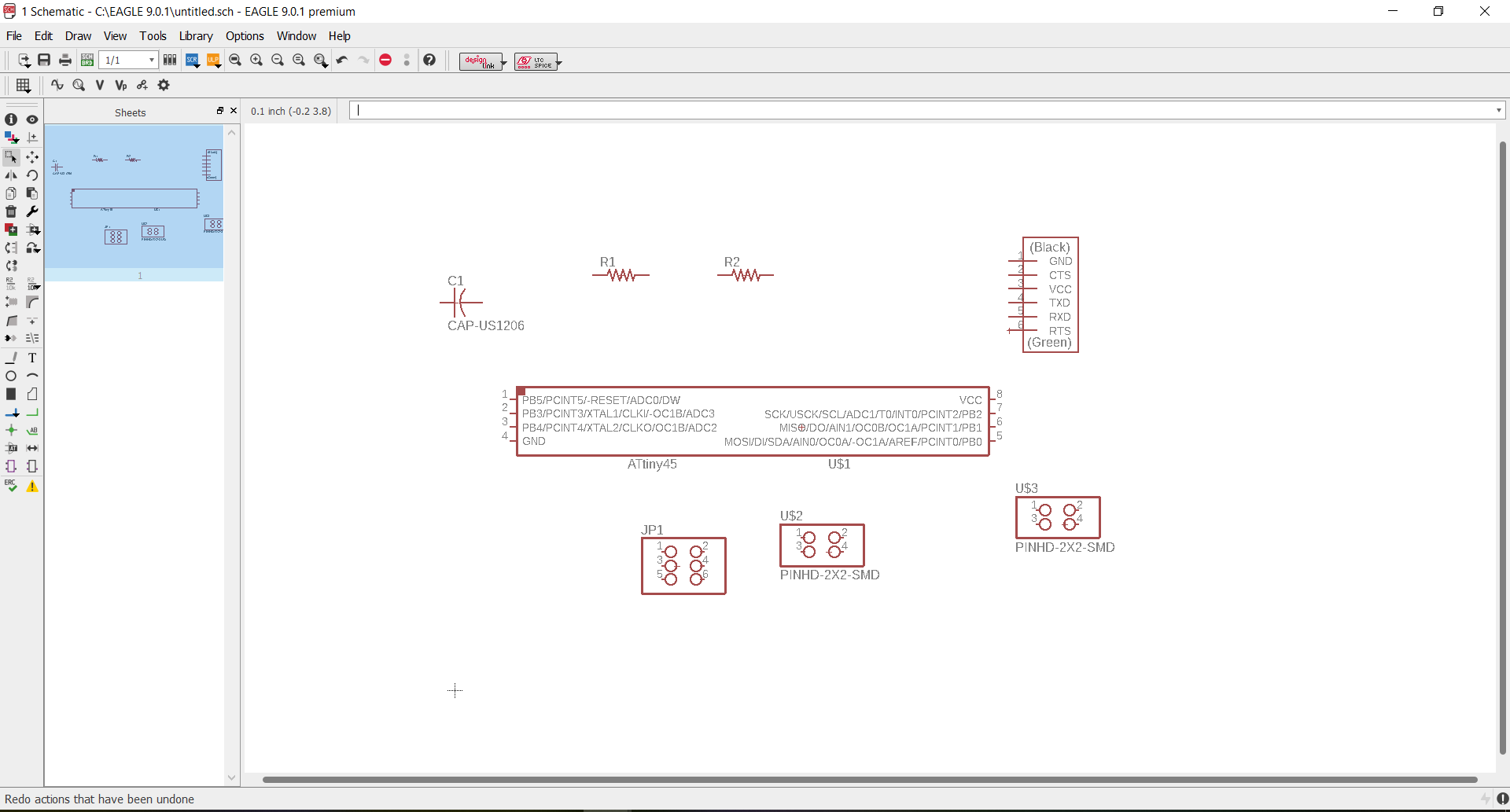
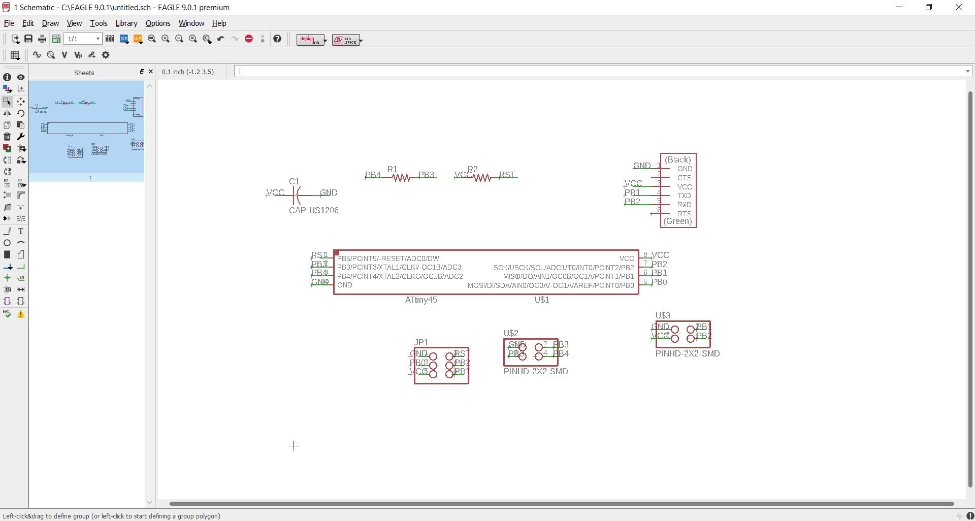
Designing my own input device
Next I made my own design of the step response board. In addition to the original components I wanted to make something that would enable it to communicate with other PCB's. Therefore I made a 2x2 pin header with GND,VCC,Tx,Rx so that it could be used in a serial bus. It makes sense to do this, because you would often want something to happen when there is a response on the input device, thereforre it should be able to go into connection with other board. To make the circuit I used Eagle:
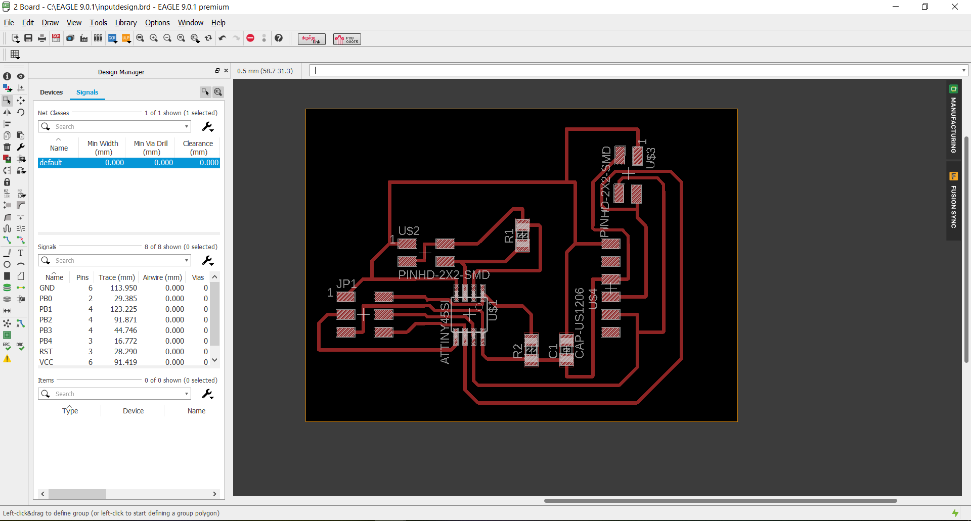
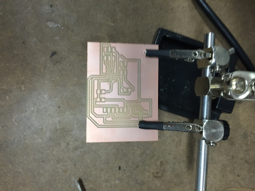
When the design was ready I did the milling and soldering process the same way as in electronics production week.
Once the board was done I had to make a small modification by moving a resistor which made the board look a bit messy even though it was fine.
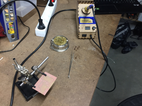
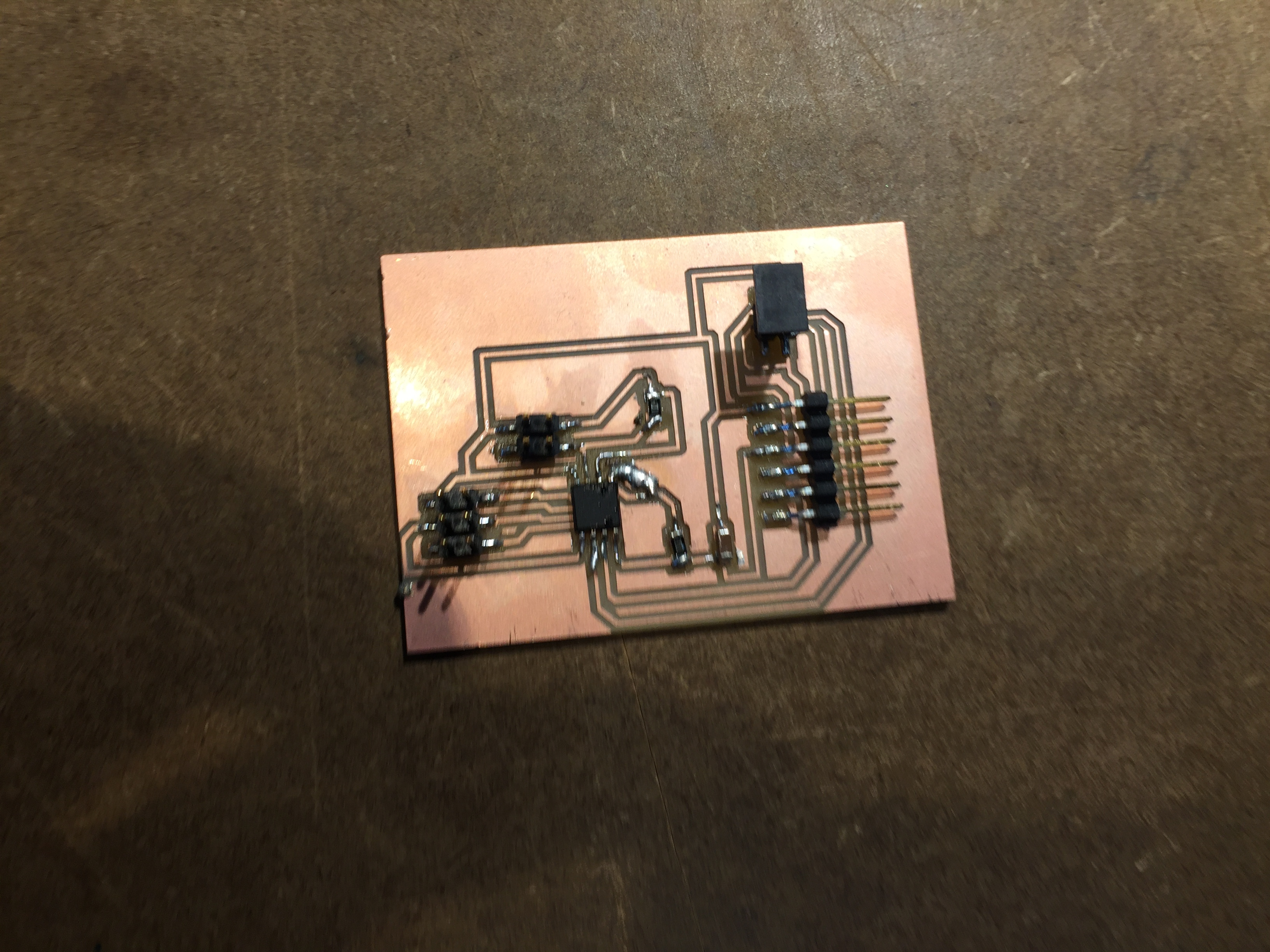
In the end I tested the connections with the multimeter which all were fine. I then wanted to use it with an Python graphical interface, but after spending a day on troubleshouting it turned out we had an issue with the Ubuntu computer we use for this in the lab. I was burning bootloader and uploading c code just fine, but it wouldn't run the Python Interface. To determine that it was the computer that had the error I tried with Niel's step response design again and still nothing would happend. Because of time management I did not get the buttom of this.
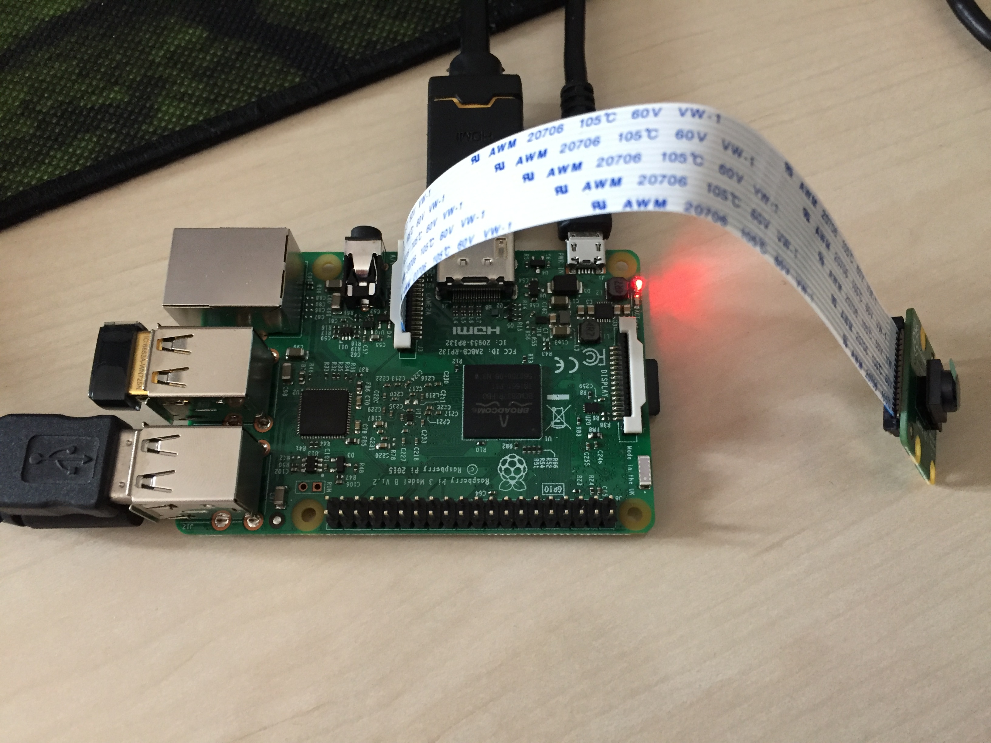
Using a camera input device for my final project
For the purpose of my final project I also spend some time this week working with a Raspberry Pi with a camera attachment since it is something I will be using in my final project. The Raspberry Pi was completely new so the first thing I did was to install the operative system following the guide on the Raspberry PI website
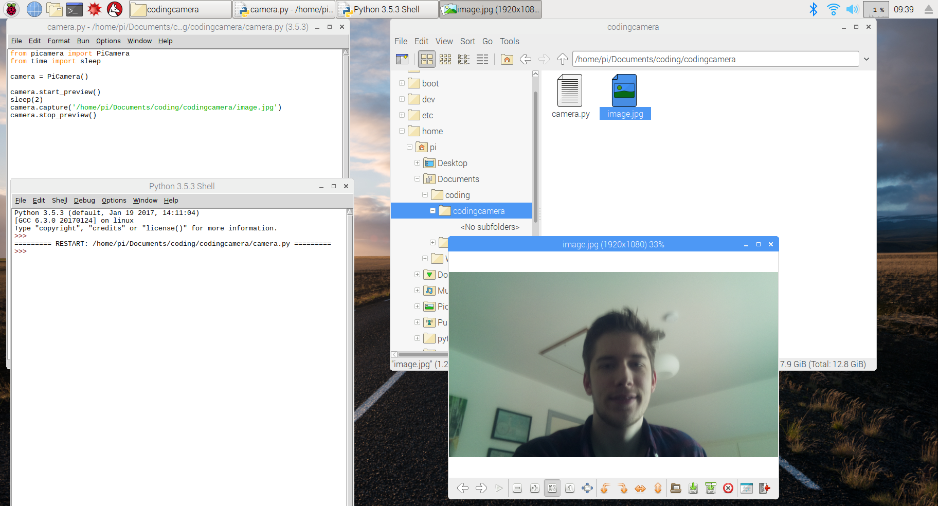
I used python to code the camera and found a great deal of sources online showing how this could be done. The code you see underneath will activate the camera to take a picture and the picture will be shaved to the desired folder. In the picture the whole process is shown: The actual code, running the code in the Python shell, the picture getting saved in the folder and the picture displayed.
Now this is a good start and I will have a final project even though my camera is only taking pictures and not analyzing them. But it will make it so much better if can make it work with face recognition. For this I have two sources I would like to try and work with: Amazon web services (AWS) and OpenCV. For this week I started by setting up AWS.
Setting up AWS
AWS is Amazon Web Services which is providing different useful tools. Creating the account for AWS was fairly easy, but making the AWS command line interface work was a bit harder. I Installed it through the terminal on the Raspberry Pi using pip.

When AWS was installed It still would not launch. I read that this had something to do with the command line path. I tried to change this by adding the path in the profile script of my shell. I was not able to do this correctly, but AWS will work if I run the command "source .profile" every time I open the terminal.
After that I was configuring AWS with my own information. I generated a set of keys, choosed region and file format. Underneath you see an example picture:

After this was working I had to set up a amazon cloud storage that I could drag and drop pictures from to be analysed. Because of time I had to postpone it and do it some other day. Instead I uploaded a picture to the light web based version of there software to get and idea of the possibilities.
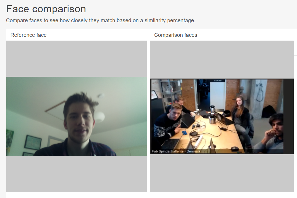
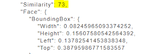
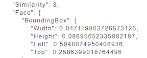
The result of the face recognition turned out to be having no matches, but when I looked into code result that the interface was providing me, I saw something Interesting. It had found a 73% similarity with my face compared to 8% and 5% with the other faces.
Thoughts
After all it was a week with some good progress even though there is still a lot more work to be done regarding input devices. Everything I worked on was something that needed to be done and something I learned a great deal from, but I have some regret that I did not work more with the designing of circuits in Eagle. I will make up for this next week in output devices where I will be designing the motor board.