Project Development
Assignment
- Complete your final project and track your progress.
Files
Weekly Tasks
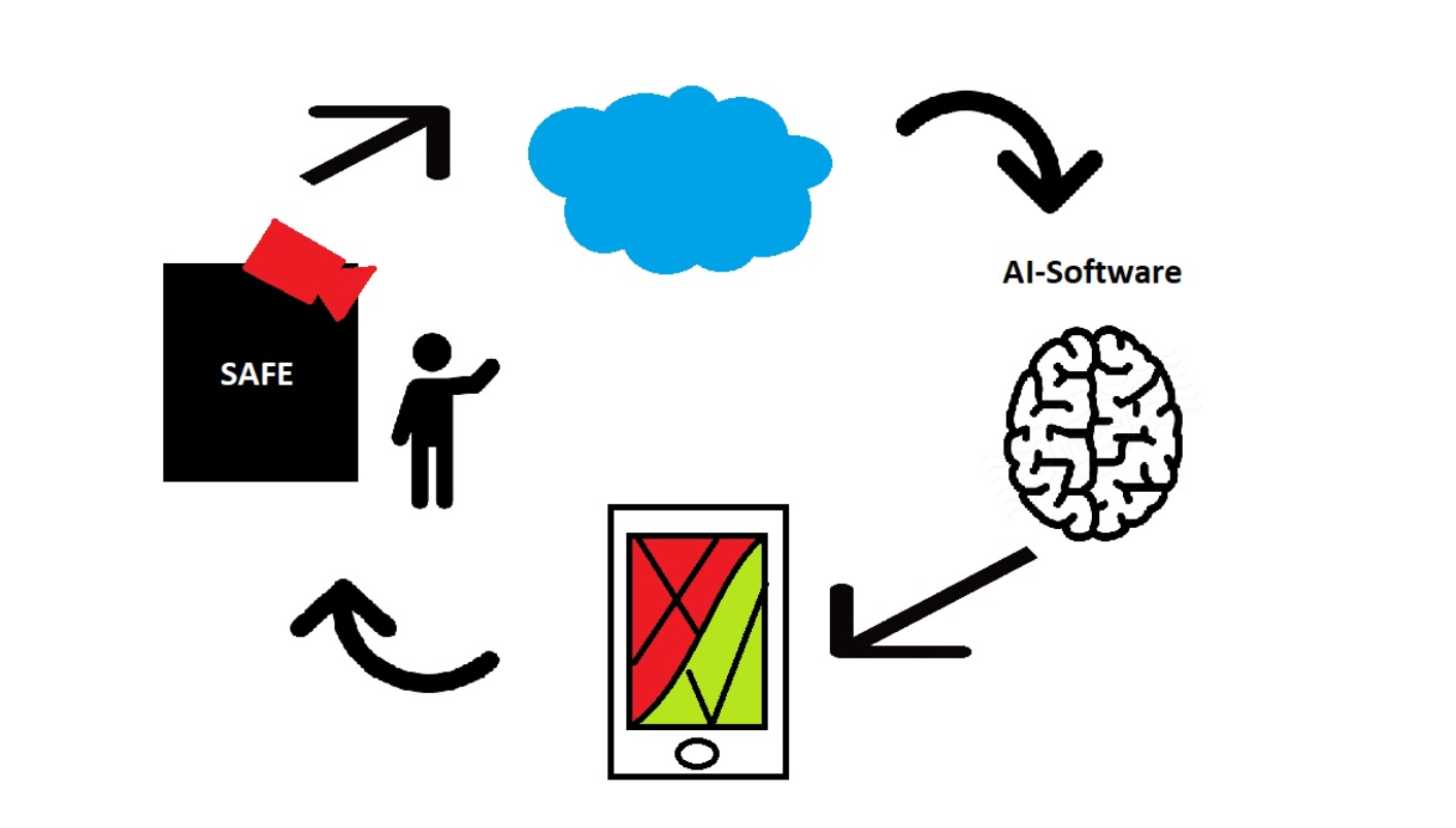
My idea for a final project is a safe with build in facial recognition so that you don't need to remember a PIN code or carry around a key. It is supposed to work the following way: Somebody tries to enter the safe and the camera takes a picture of the person. The picture will be send to the cloud where a software will try to identify the persons face. If it's the owner trying to access the safe, it will send the information to the connected device and the safe will open. If it's someone else trying to unlock the safe, the information with a picture of the person that did not get through facial recognition will be sent to the connected device and the safe will stay locked.
In order for my project to work, I need to make the following items: The case it self for the safe, a locking mechanism, a user interface or some sort of application running on a device, a camera that works with AI-software. During the first week I talked to both Bas and Niel about my project. It was mentioned that I should really think carefully about the packaging of my product. I was given the tip to add another wall in my box where all the electronic parts can be stored since you don't want them sticking out everywhere.
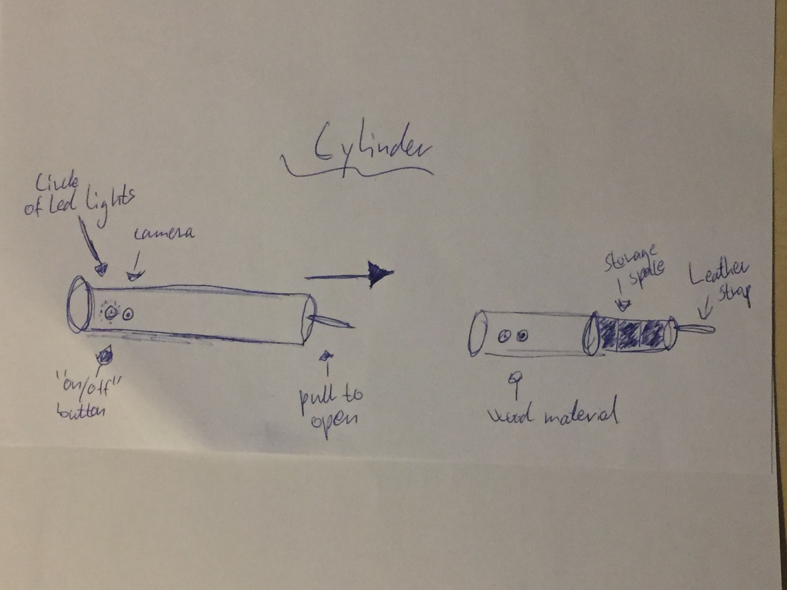
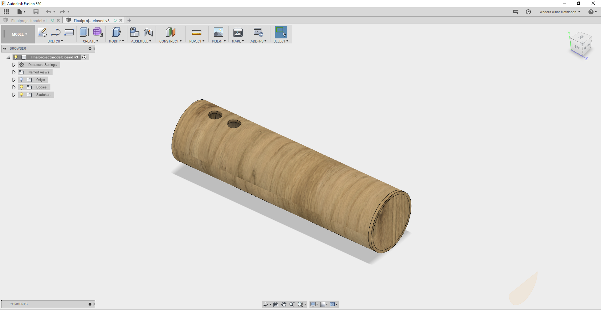
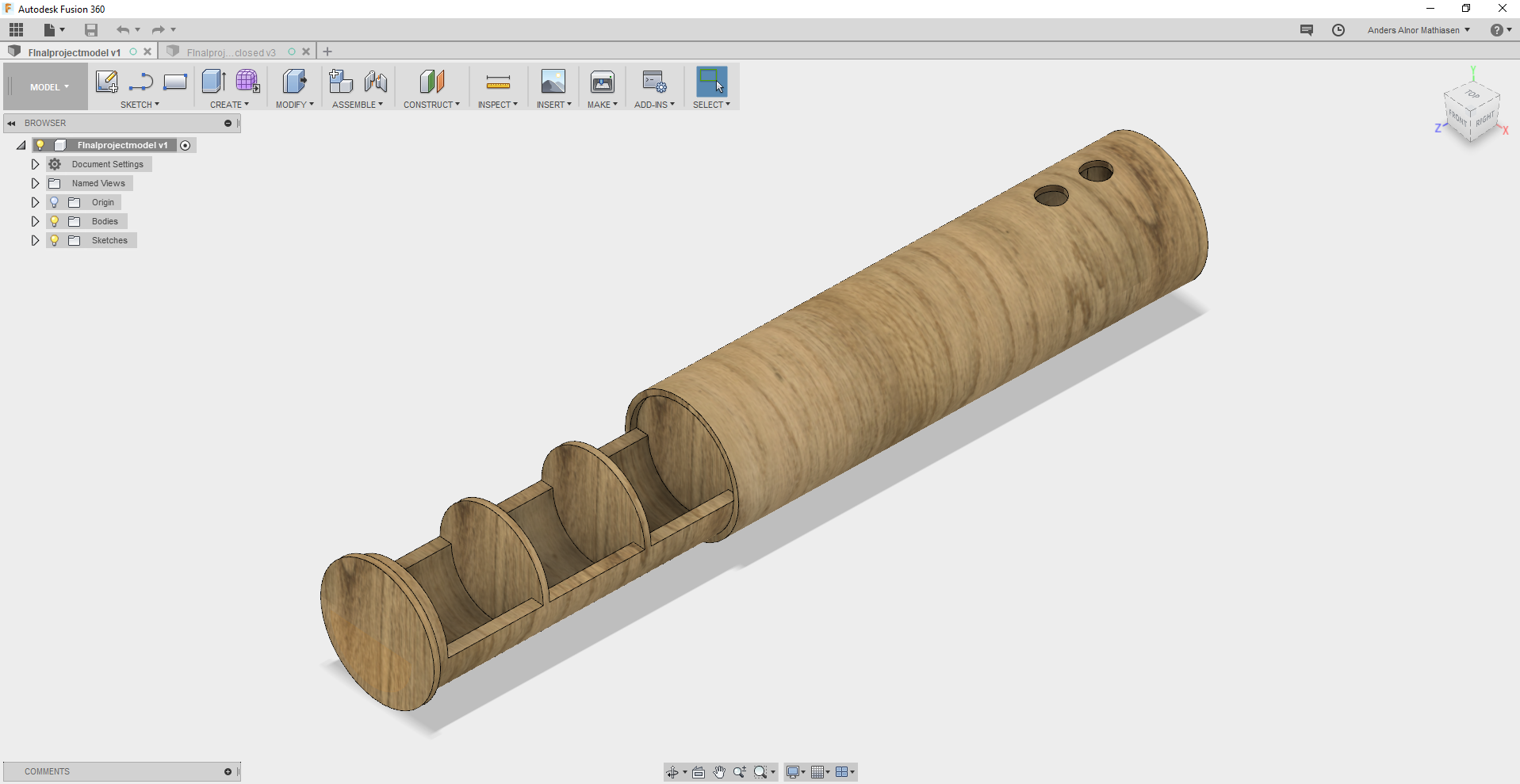
In week 3 when doing computer-aided design I turned one of the sketches I have made into a 3D model in Fusion 360. My thoughts about this design is that I wanted to make something different from a traditional squared box, so instead I went for the cylinder. I want the material to be bamboo if possible or some other light wood that has a good feel to it. The rooms for storage is quite small and the model is not very big since I want it to be something you could carry around in a bag when needed.
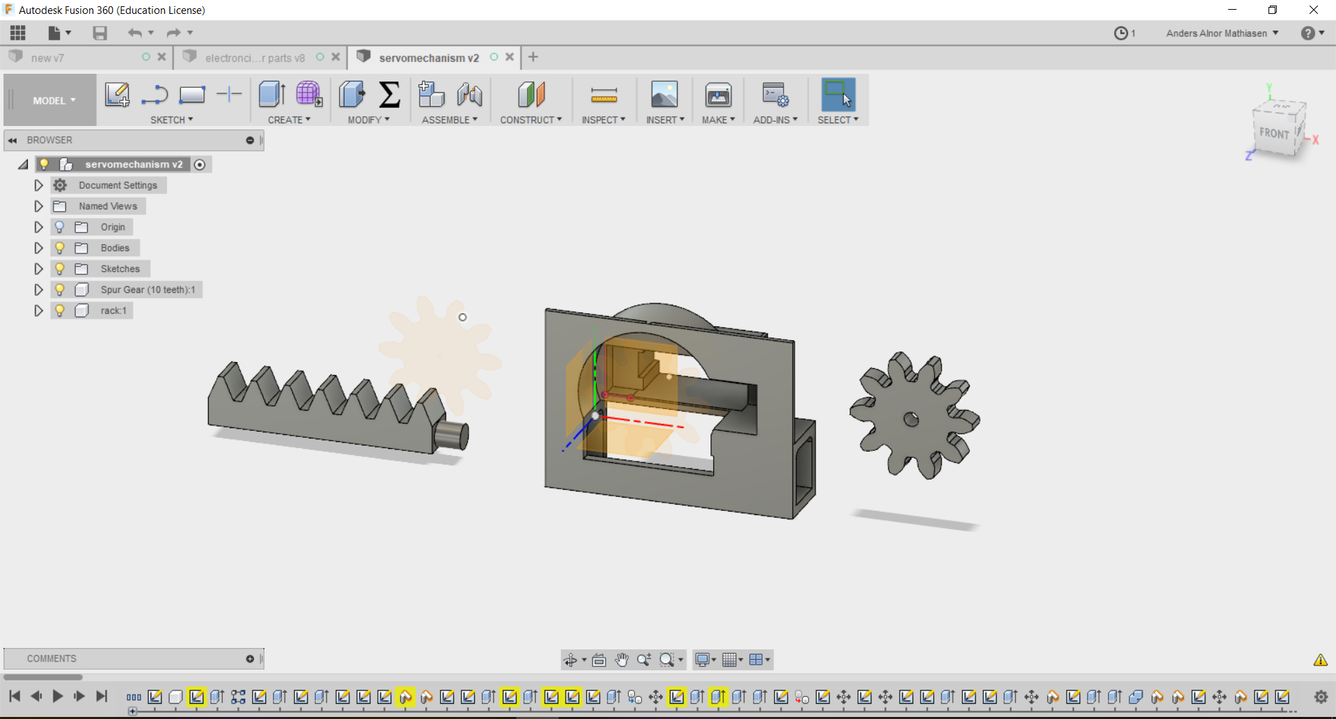
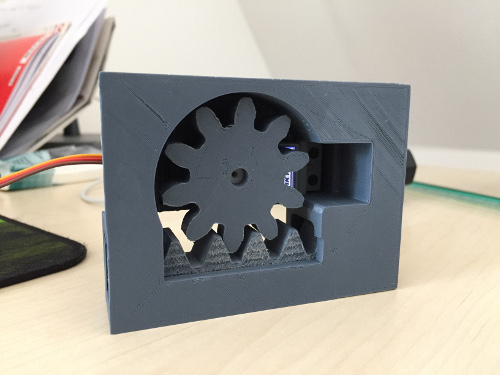
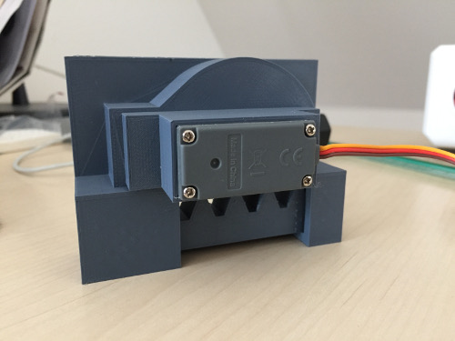
In week 6 when doing 3d printing I decided to make a locking mechanism for my final project. I used a rack and pinion design that I specified to go with the small motor we have in the fablab. The mechanism is supposed to be mounted with the pin of the motor facing towards a flat surface.
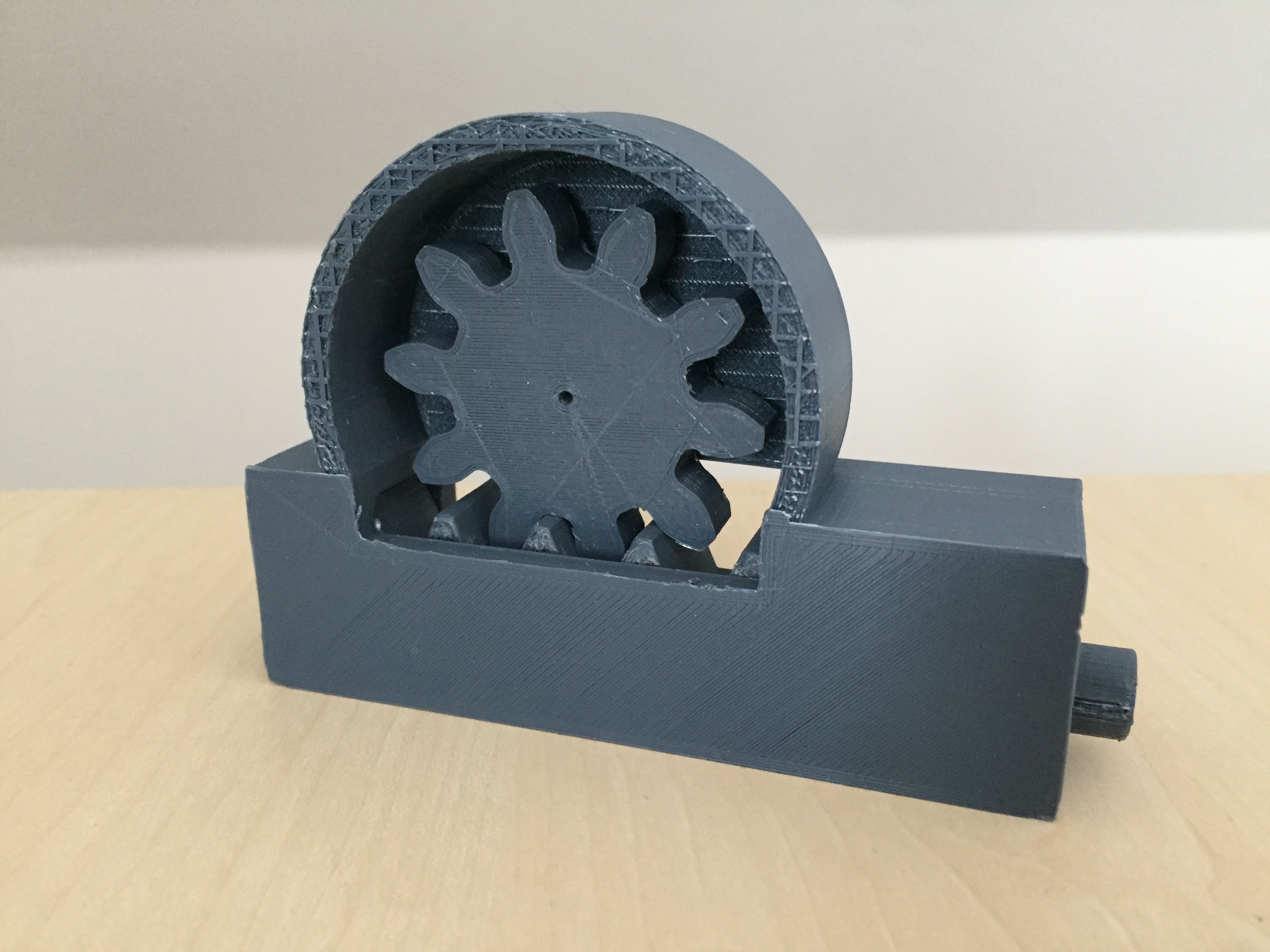
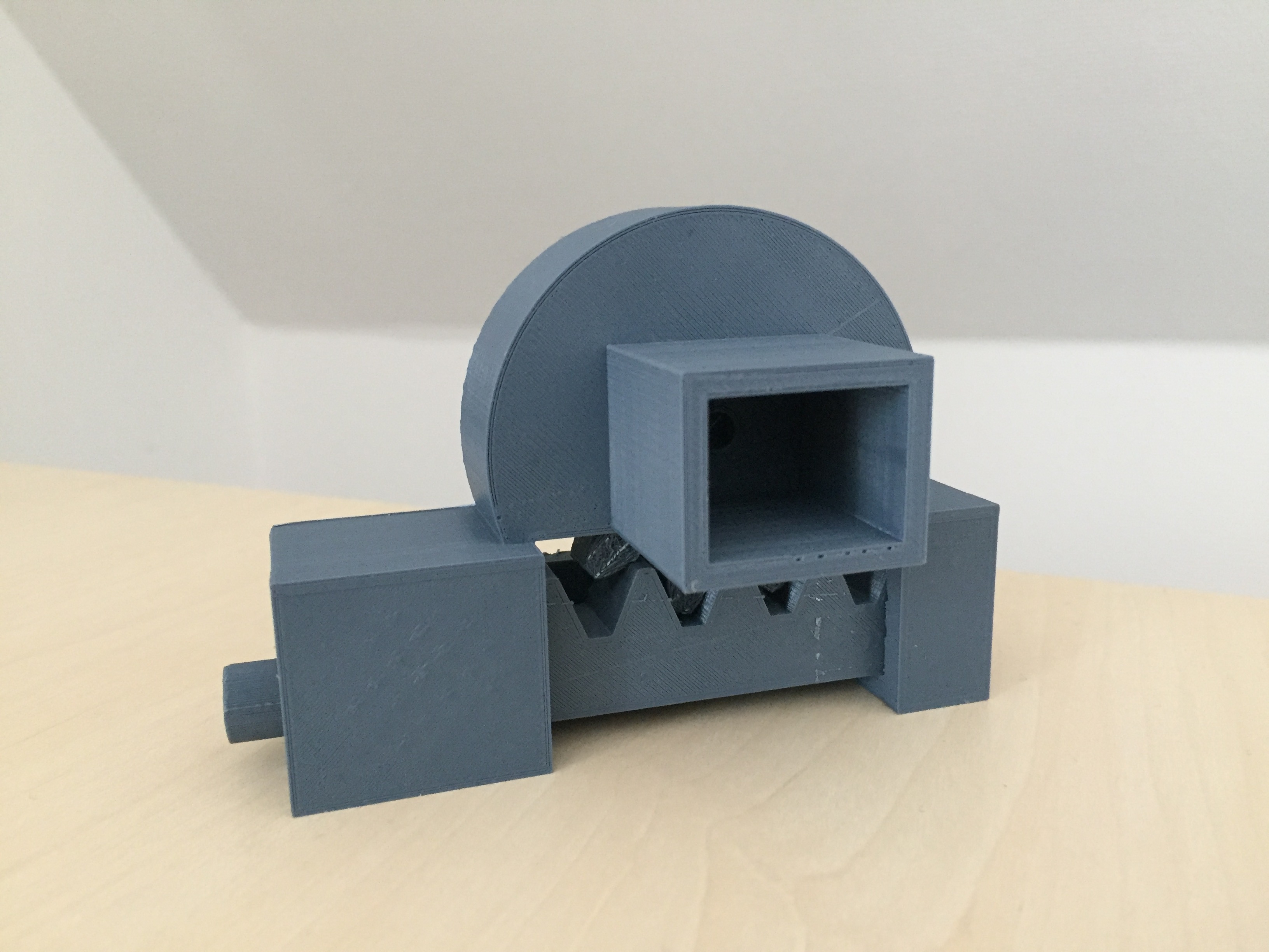
Later I made another locking mechanism since I figured that a servo motor would be a better solution for a rack and pinion design.
In week 11 about input devices I started by laying out the electronics I would be needing for my project illustrated in the following sketch.
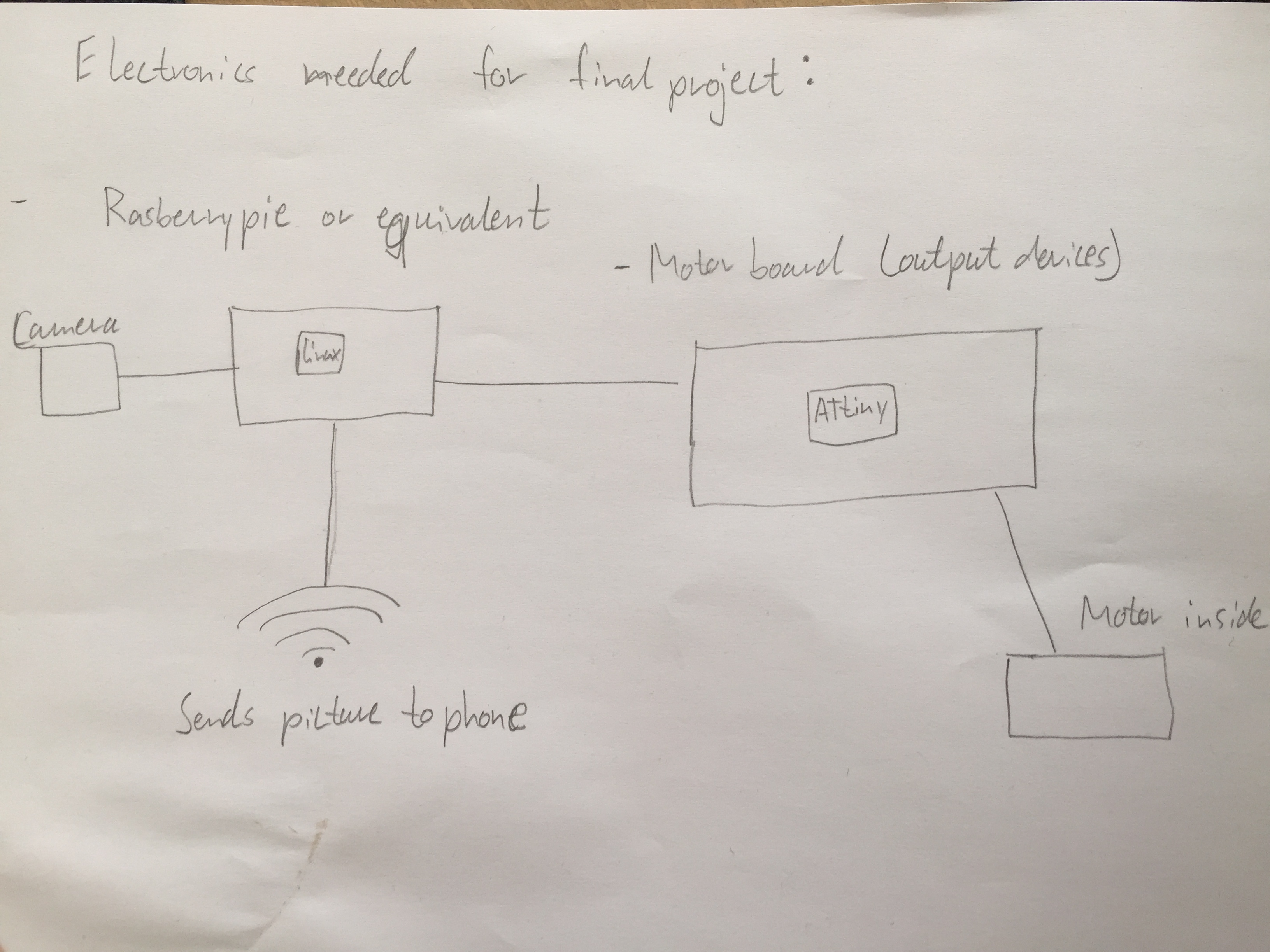
The sketch shows a Raspberry Pi with a camera and wifi attachment talking to a PCB , controlling a motor, over serial communication.
In output week I also worked with the Raspberry Pi to take pictures and use facial recognition form Amazon Web Services.
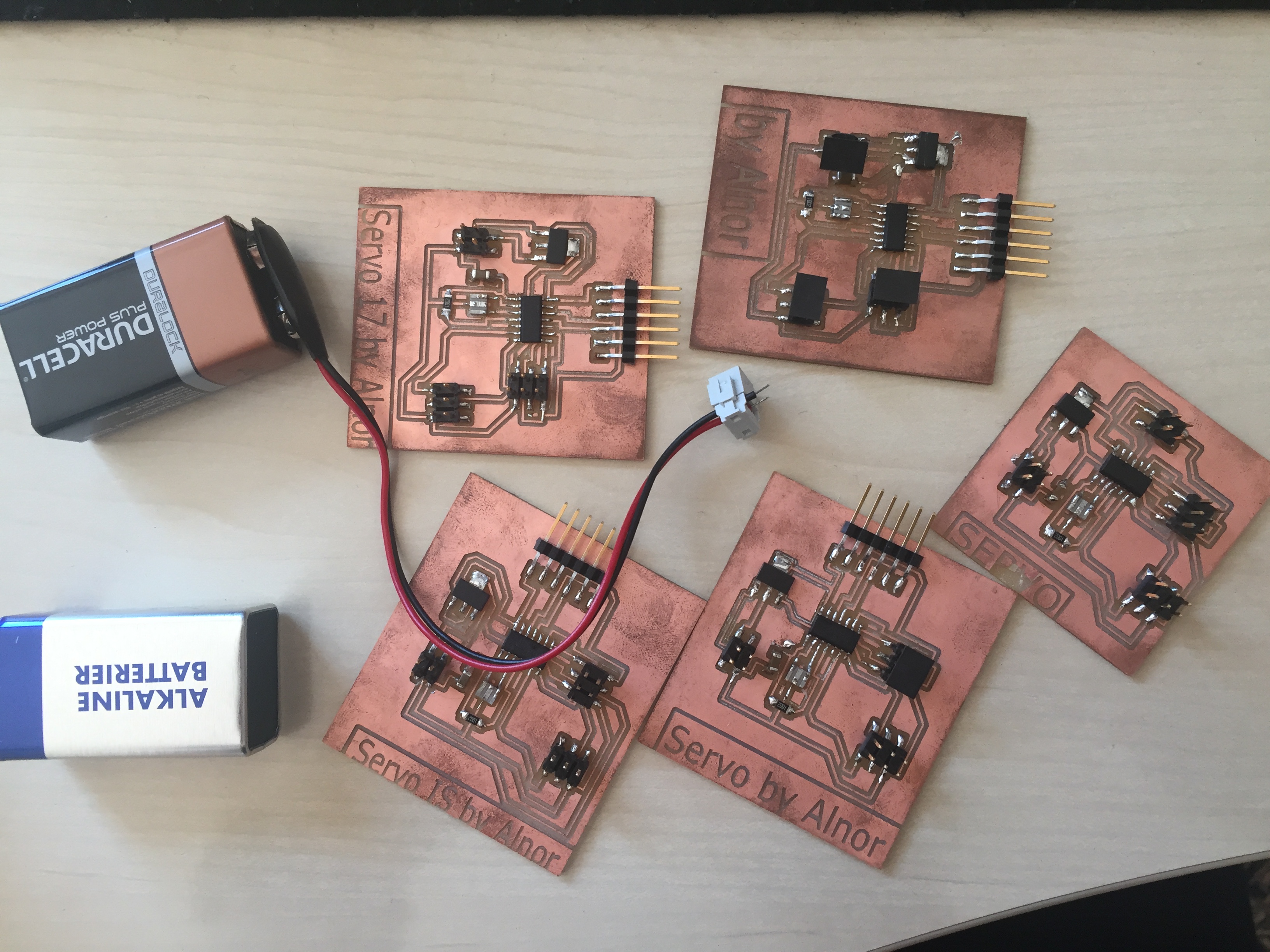
In week 12 about output devices I worked with servo motors but I couldn’t make them work with this trace. The trace is a evolution Neils servo board but only for one servo instead of two and a FTDI jumper for serial information.
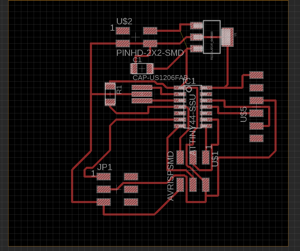
The big problem with this board is that the regulator is different from the one Neil uses. I have tried with different ones but I believe the error still lays in the pin layout of the regulator.
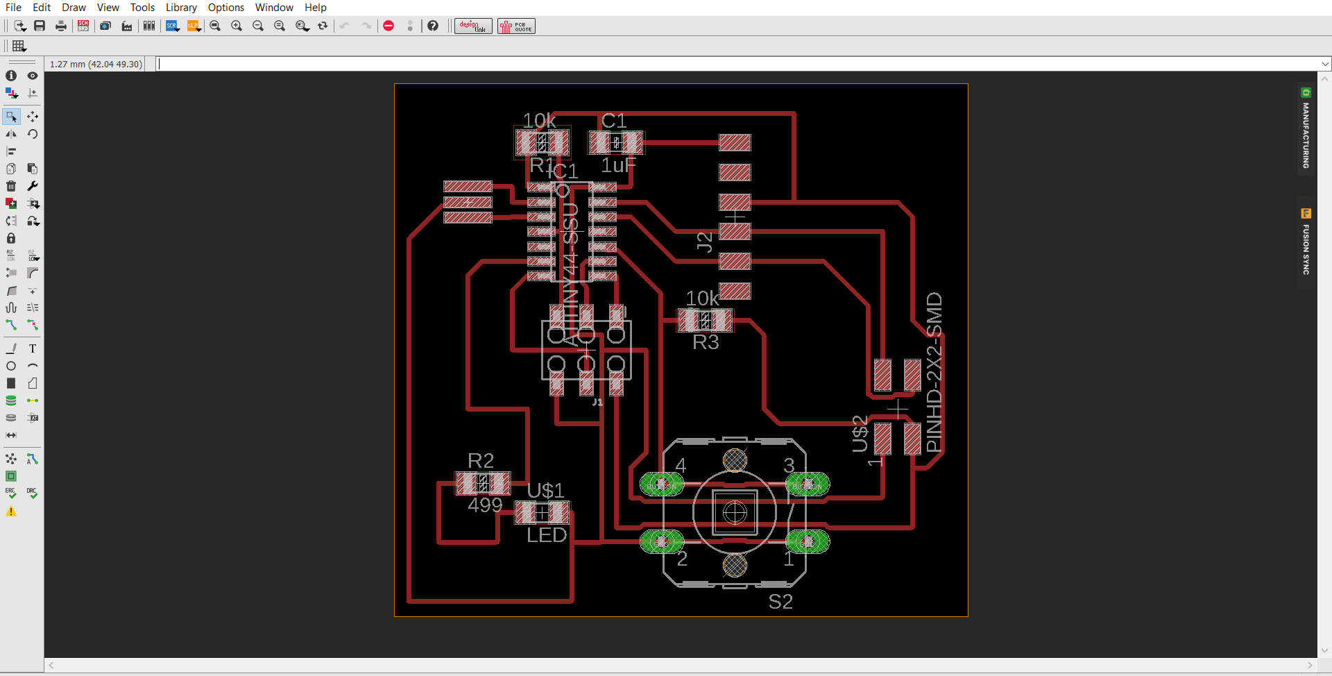
Instead of making the servo board work I instead managed to get a version for the echo.hello.world board to work with a servo motor. I also added another LED and Button which would be suited for the board and a 2x2 header for serial communication if I would need to attach other boards.
I tried to code in Arduino IDE but I could only make the c code provided by Neil work. I think it has something to do with the libraries in Arduino where it can be hard to see what is actually going on.
I changed the code with the pins I was using and also the positions of the servo motor so that they would fit to how I wanted the locking mechanism to act.
C code
The c code is what will be running on the PCB with the button, motor and LED, it needs to control these things mentioned but also work with sending information via. serial to the Raspberry pi. To do this I found examples from different codes where these actions were partly done. I used the servo code, the serial bus code and the echo world code provided by the Fab Academy lectures. To illustrate this here is the pins listed together with each part of the code:
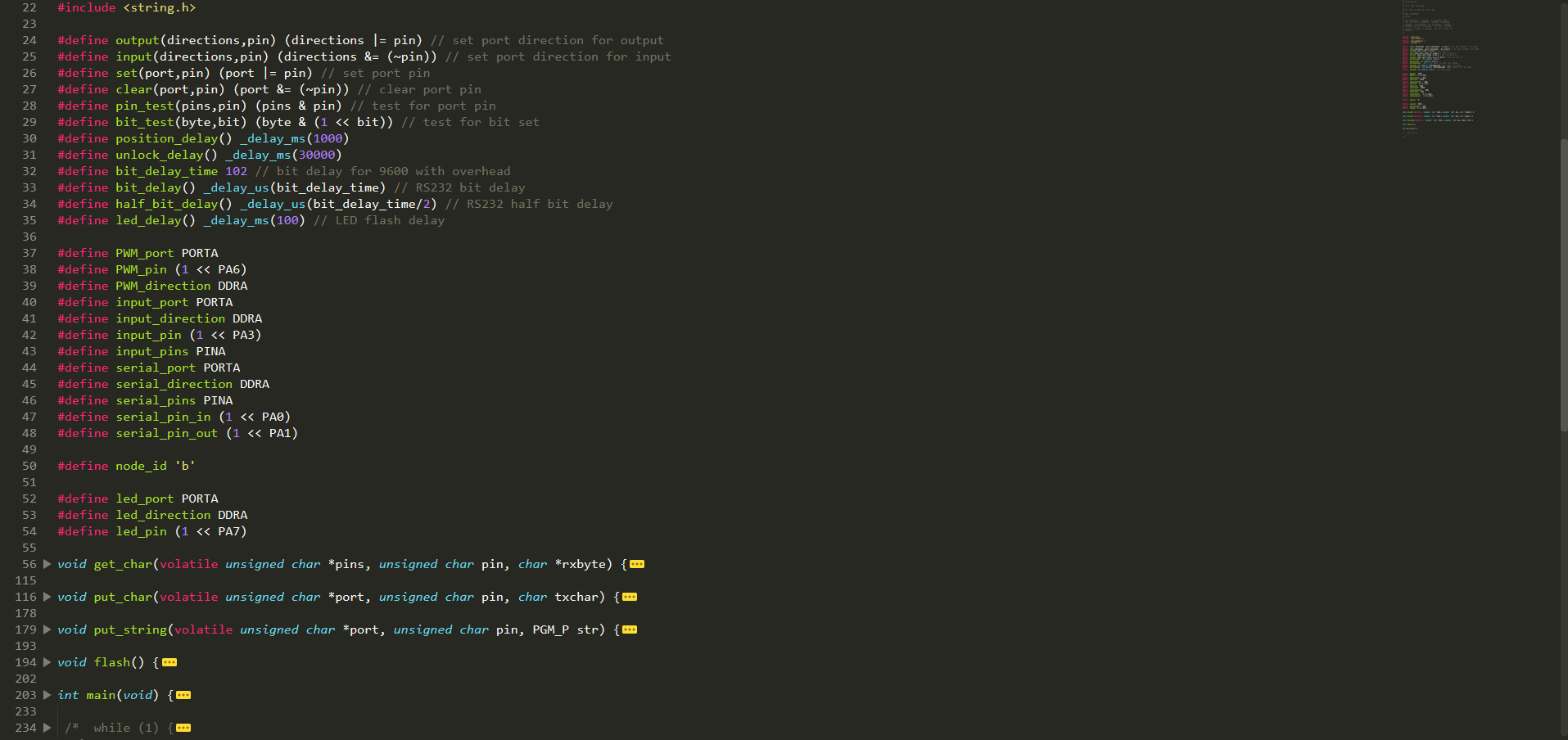
I made all of the things work separately. The motor would move, the button would send a letter when It was pressed, and it could also read serial information in the code and make the motor turn based on when I was receiving this information, but when I wanted to combine everything I ran into some problems.
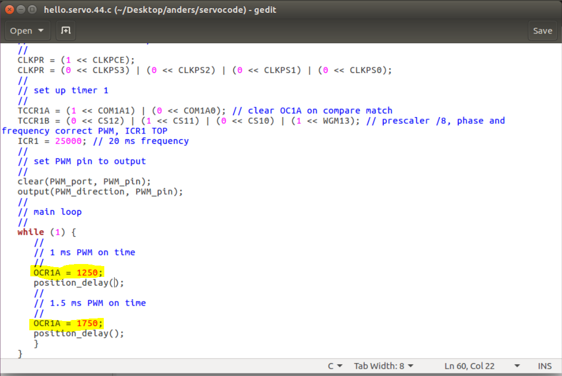
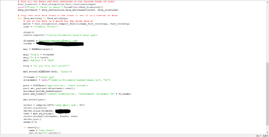
Since I made everything work separately I was confident that the error was in the main loop. This is how the code looked like combined but without working.
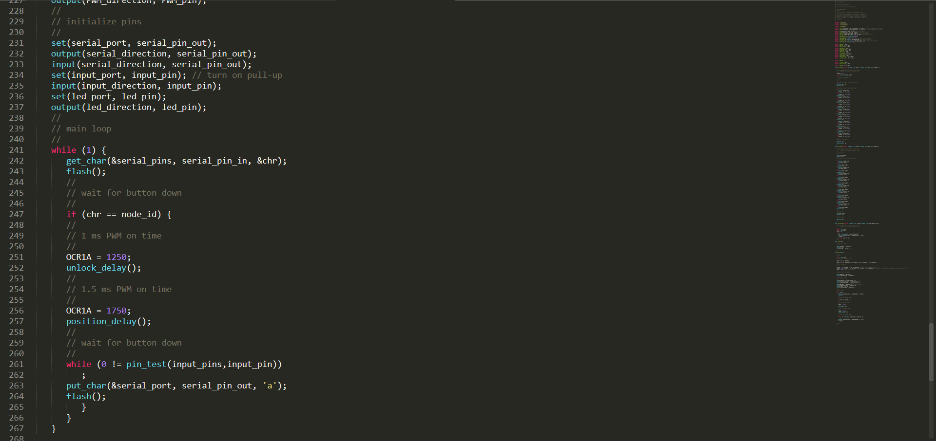
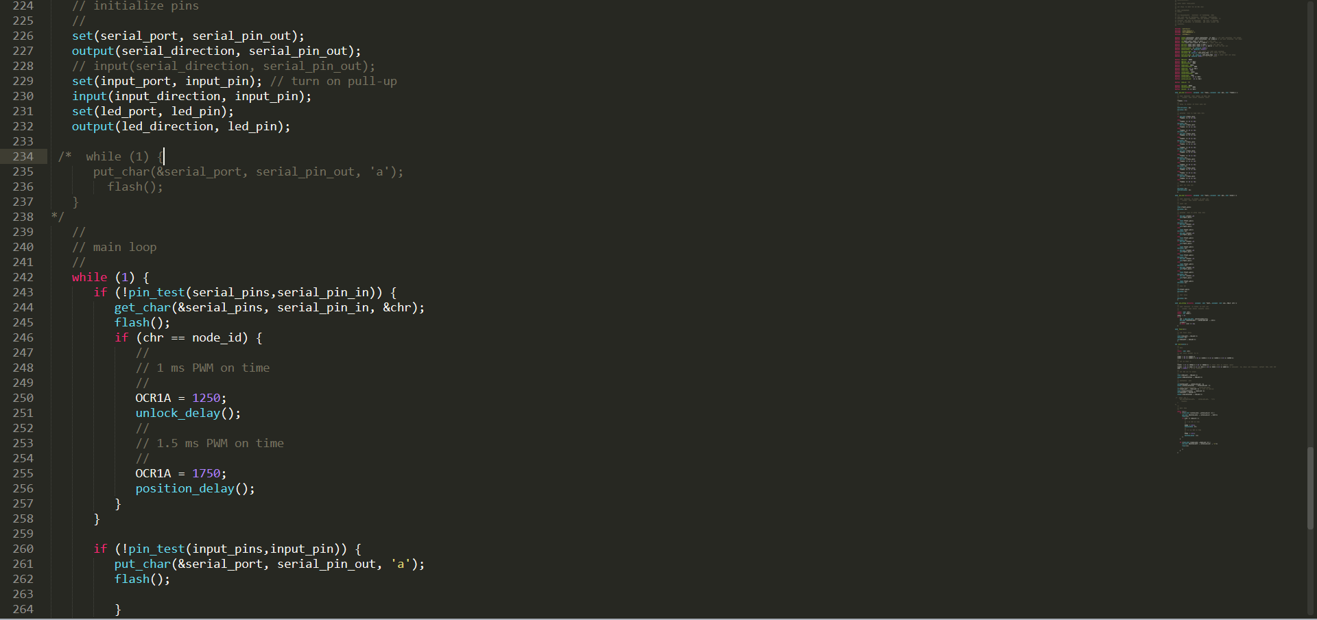
After getting some help from Bas and looking further into it myself the problem was solved, wich was that under "get char" it would be waiting for an input which meant that nothing else of the code would run before getting any input from the serial connection. Also there was an error in initialize pins which is outcommented in the picture. The other line which is outcommented in the main loop, was to test wheter it could send out information at all. This was used to localize the errors in the code. To have a closer look at the code, download the file
.
Setting up the Raspberry Pi Python code
The code running on the Raspberry Pi had to do a few things according to the code running on the microcontroller. It had start running the code when it's receiving and "a" from the button. Check with the camera if its the owner trying to access the box, send a picture of whoever is trying to access the box to a mobile device and if it's the owner send a "b" through serial communication back to the microcontroller.
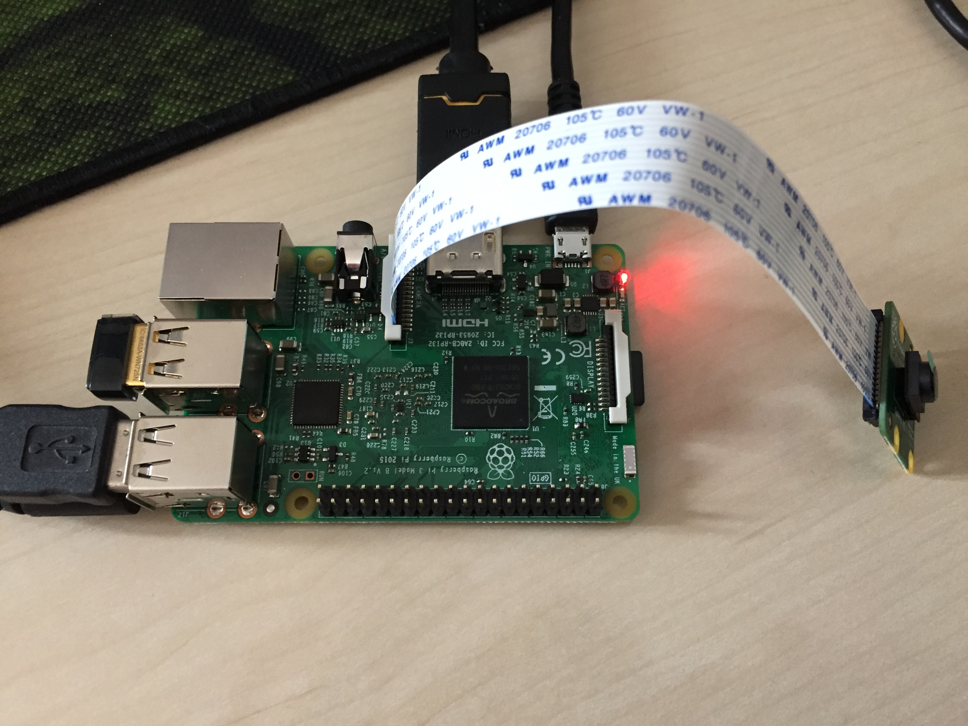
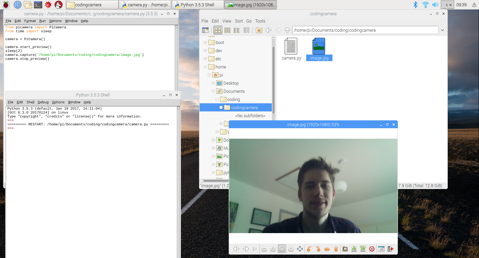
The first thing was to make the camera attachment work. There is countless examples on the Raspberry Pi website on how to do this. This is how I made it work:
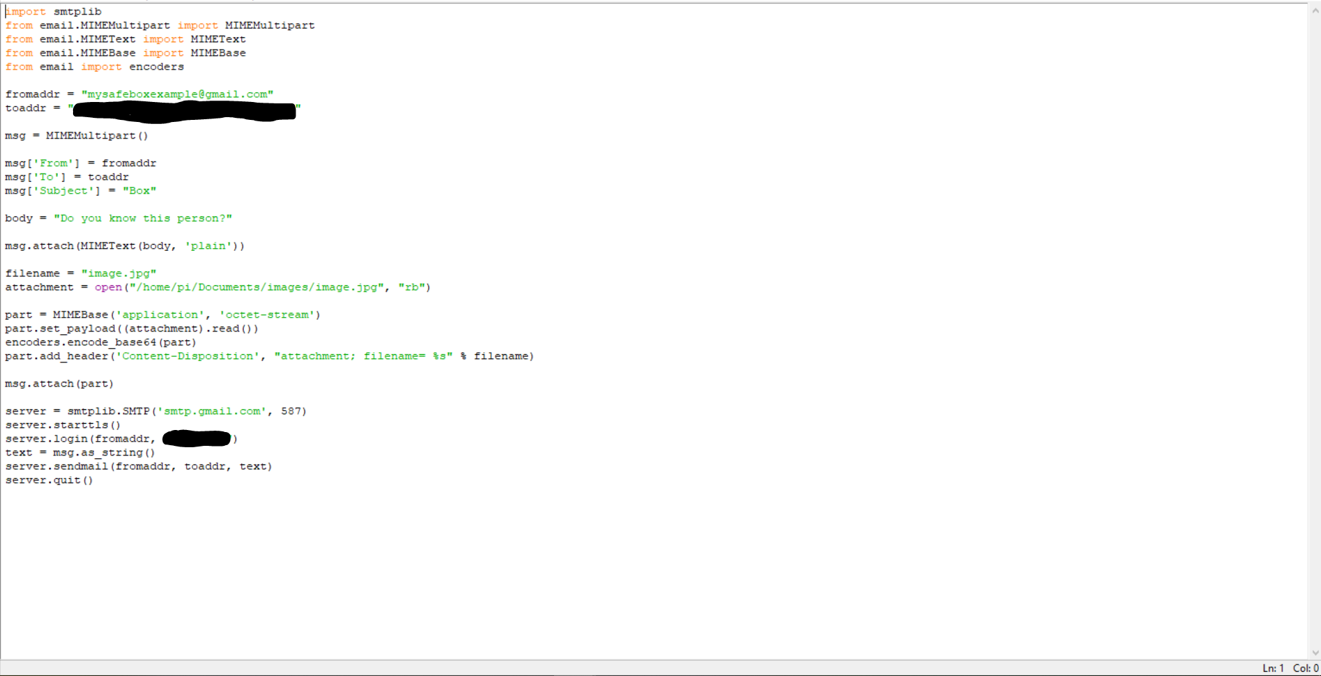
A way to get the pictures onto my mobile device is through email. I found an article explaining how to do this. Last example on this page should be suited. The only problem was that it was made for Python 2. To use it with Python 3 the only correction that had to be made was the name of the libraries imported. For sending emails with attachments it looked like this:
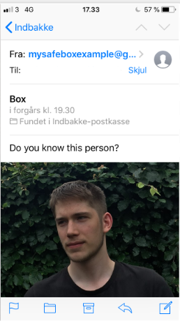
This is what it looks like on the mobile deivce:
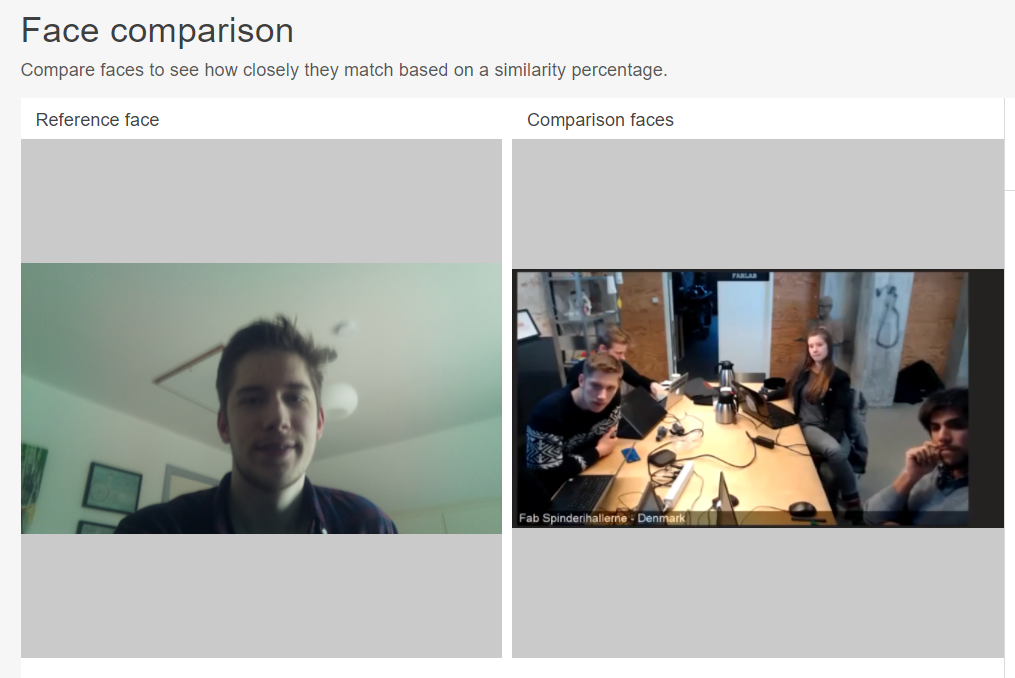
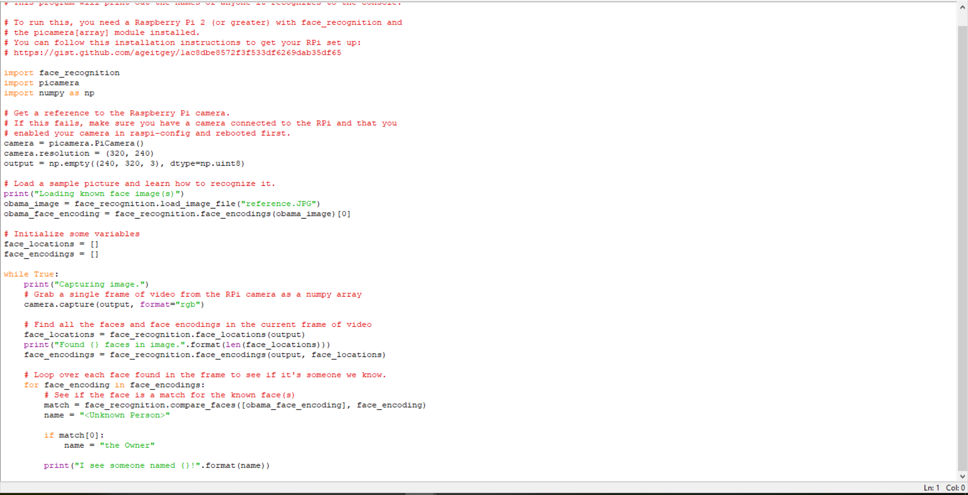
To make the camera recognize my face I already had some experience with AWS from input device week. But it seemed like something that would be hard to integrate with the time I had. Instead I found this page where a guy named Adam Geitgey made face recognition software using dlib which is a C++ libary about machine learning algorithms.
I followed the instalation guide and used one of there examples where I put in a picture of me as reference instead of the one they were using of Barack Obama. It didn't work in the beginning but after searching for an answer it seemed like from this link that I had to install another thing with the error I was getting. After that the example underneath was able to recognize my face:
In the end I figured it would be good idea to remote control the Pi when was it was in the box. For this i used a service called VCN connect. I was setting it up using this guide.
Now that the core of the code was working I put it all together, and used Pyserial to make it talk to the microcontroller. The code will start taking pictures when it is receiving an "a" and will send out a "b" if it finds a match to the reference picture. It is therefore made in relation to the previously mentioned c code on the microcontrollerwhere the button is sending out an "a" when pressed and the motor in the locking mechanism will turn when it receives a "b".
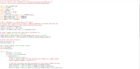
To get a closer view of the code, download the file.
Designing the box
The last thing I had to do was to design a box where everything could be integrated nicely into. I already had my 3D model of how I wanted it to look like but to get more specific I found these examples online which fitted the style that I wanted.
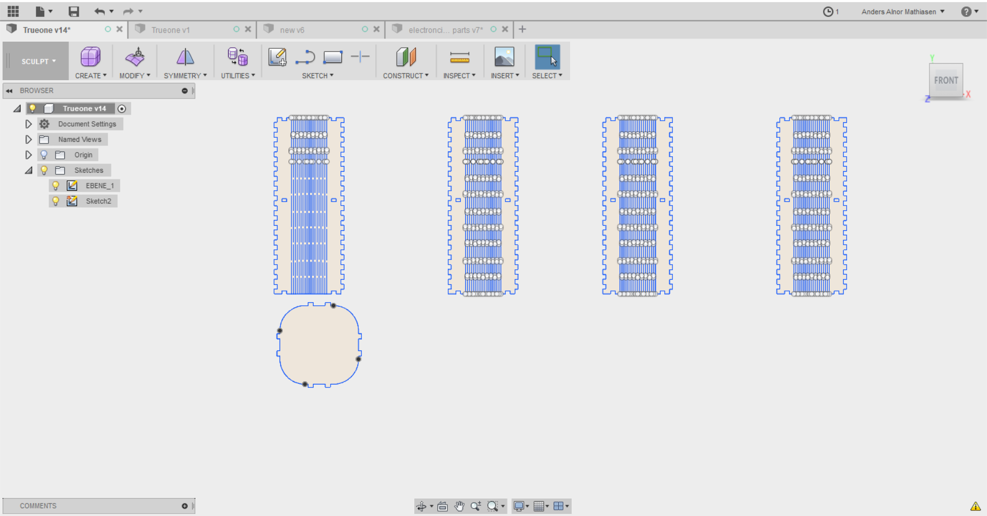
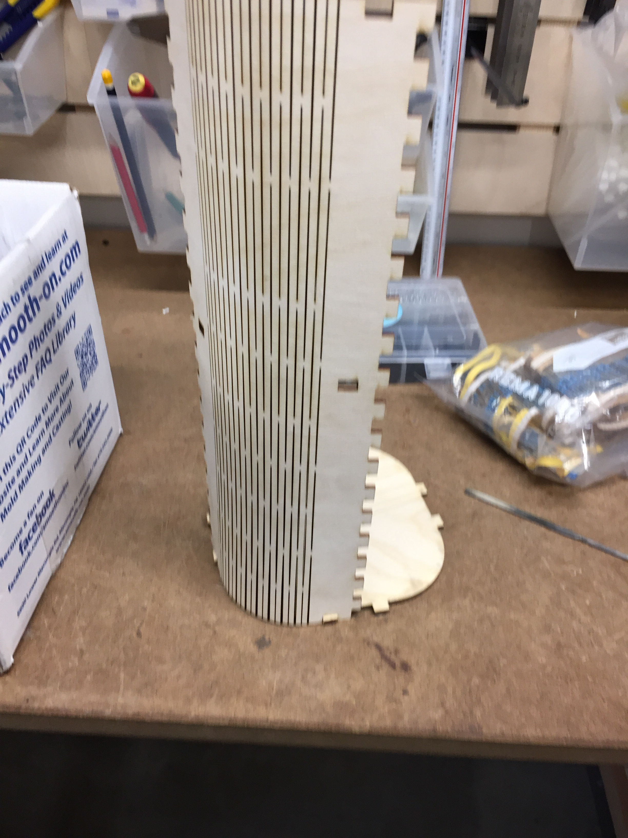
I found an example online, which I unfortunately can’t find again, which showed how to make this grid system in order to bent wood so that It could make up this cylinder alike shape. I imported the example into Fusion 360 and scaled it to the size I needed for my project. I added another set of wholes and a circular shape to fit into these holes (see picture), which would function as a stopping block for my rack and pinion designed locking mechanism.
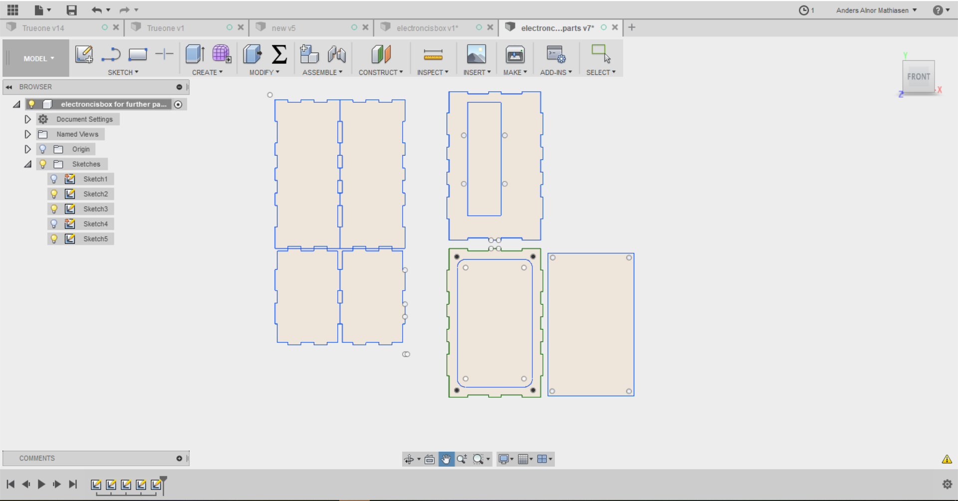
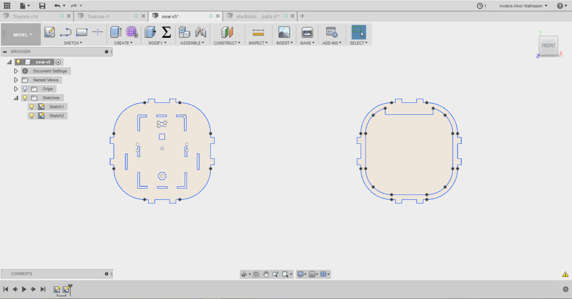
Now the cylinder shape was in place, I needed something to hold all of my electronics. I figured that the lid with a cubic box underneath would be a good solution, since It would then be able to fit the button, led, camera and charging usb in the lid where it would be easy accessible. I used boxmaker to to make the tabs for the case which I then imported into Fusion 360 to make holes in the lid for it to fit into. I also changed the sides of the box so that I would be able to open it again. On one side I made a hole for the Raspberry Pi and on the other side I had a piece which can be screwed on and off.
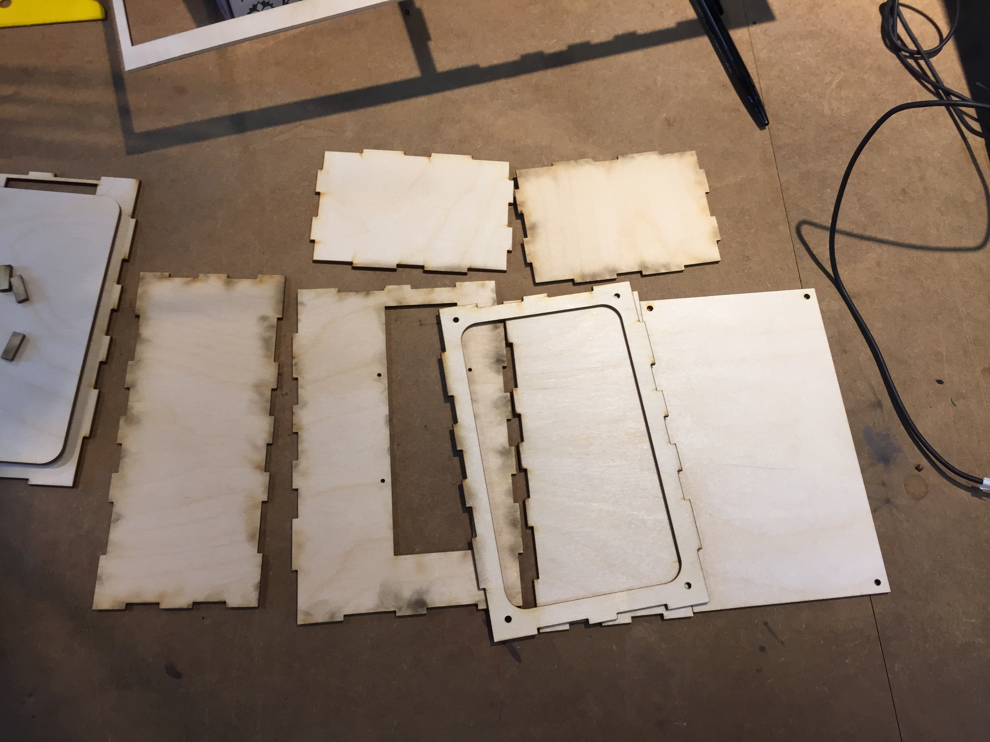
All the parts that I needed to laser cut therefore looked like this:
Assembling
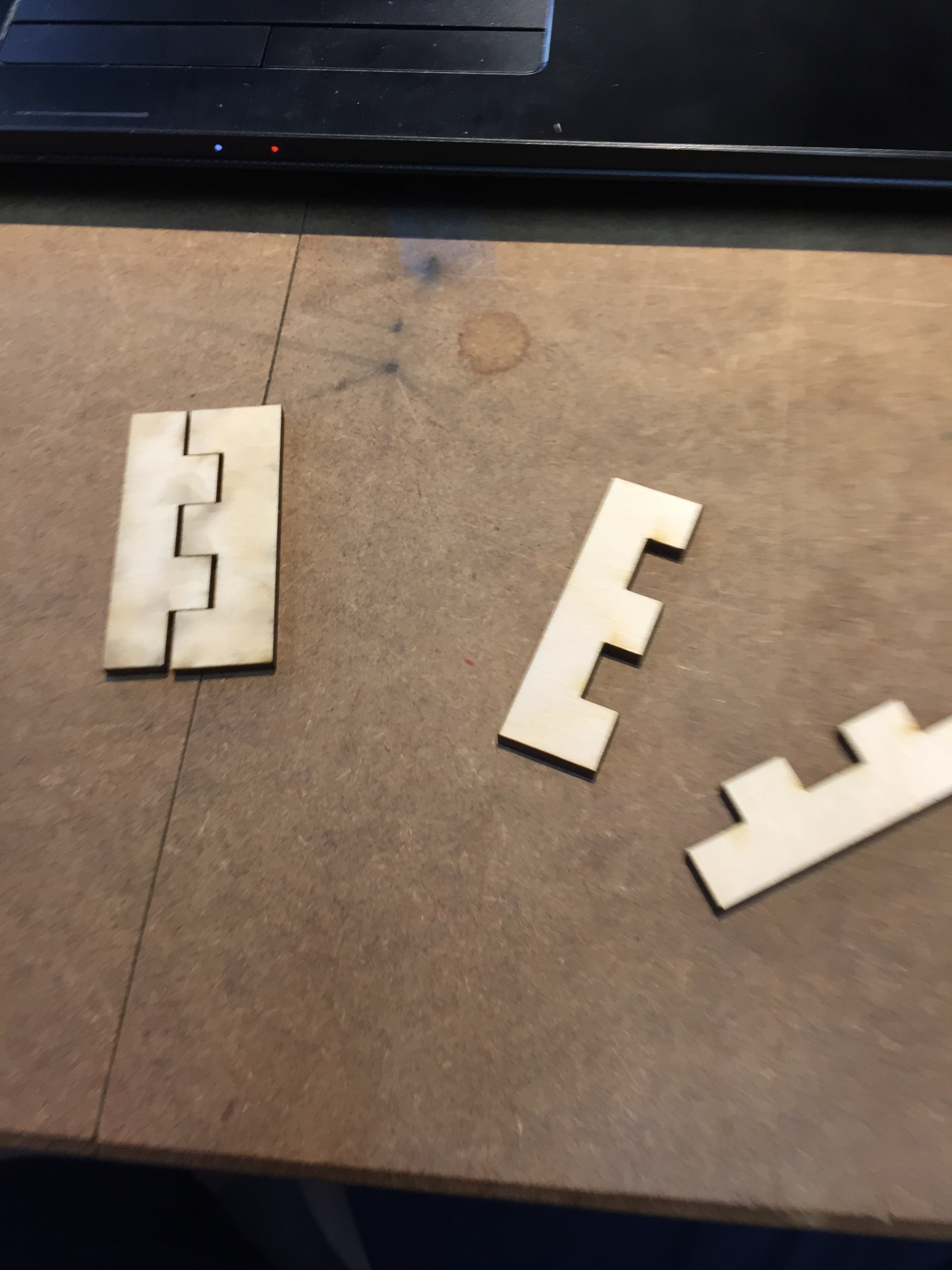
All of the files from 2D modelling was meant to be laser cut. I decided to use plywood since it had a nice finish compared to the cost of the material. Before cutting everything I made a few tests to see if the kerf was okay:
The lid I had to make a few times since every time I did it there was always something that surprised me which I only could have found out be cutting the previous version and then trying to fit the parts it had to hold.
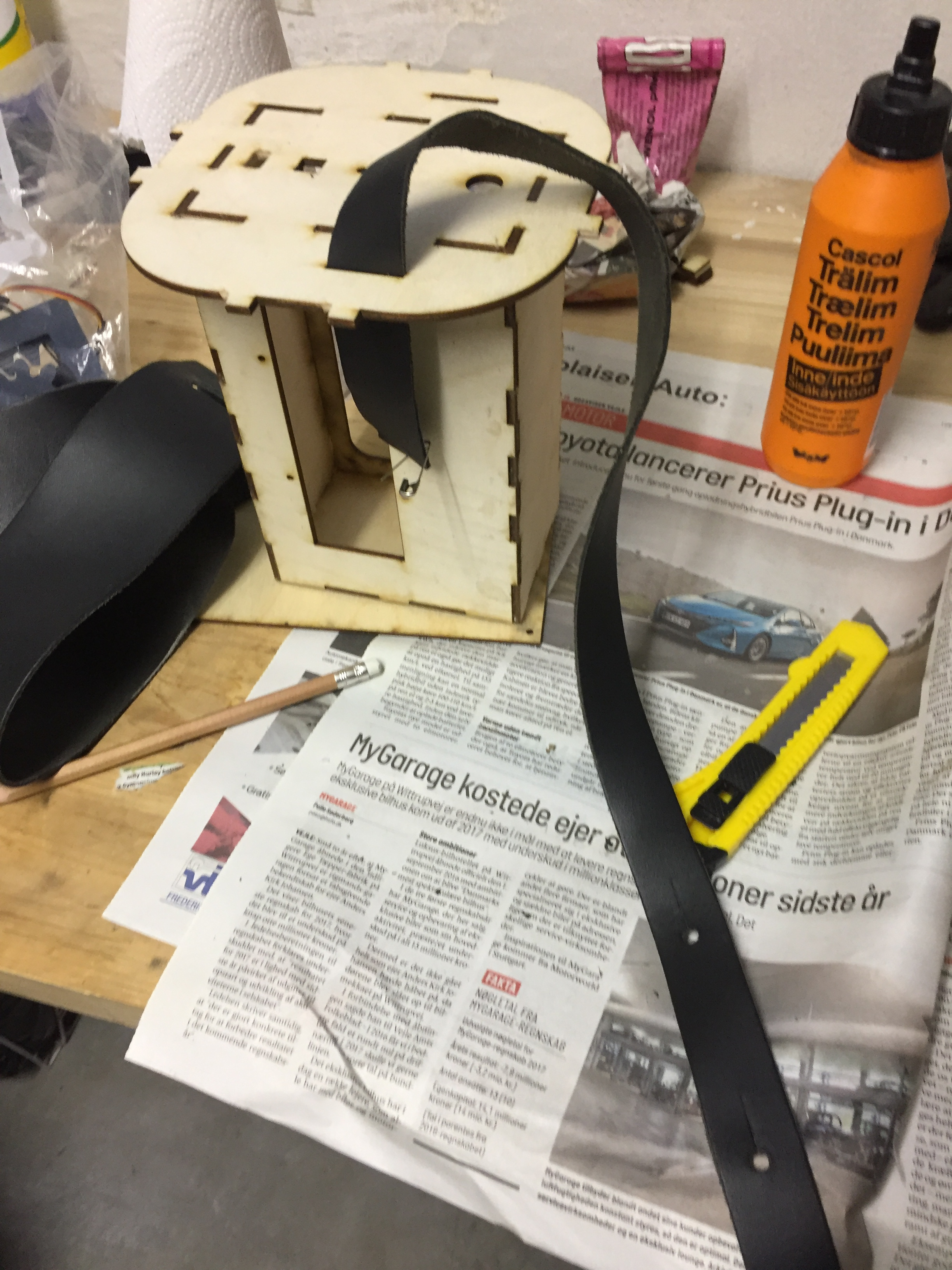
When assembling the wooden parts I used some glue. Maybe it could have worked without glue but I think that there was no point taken the risk.
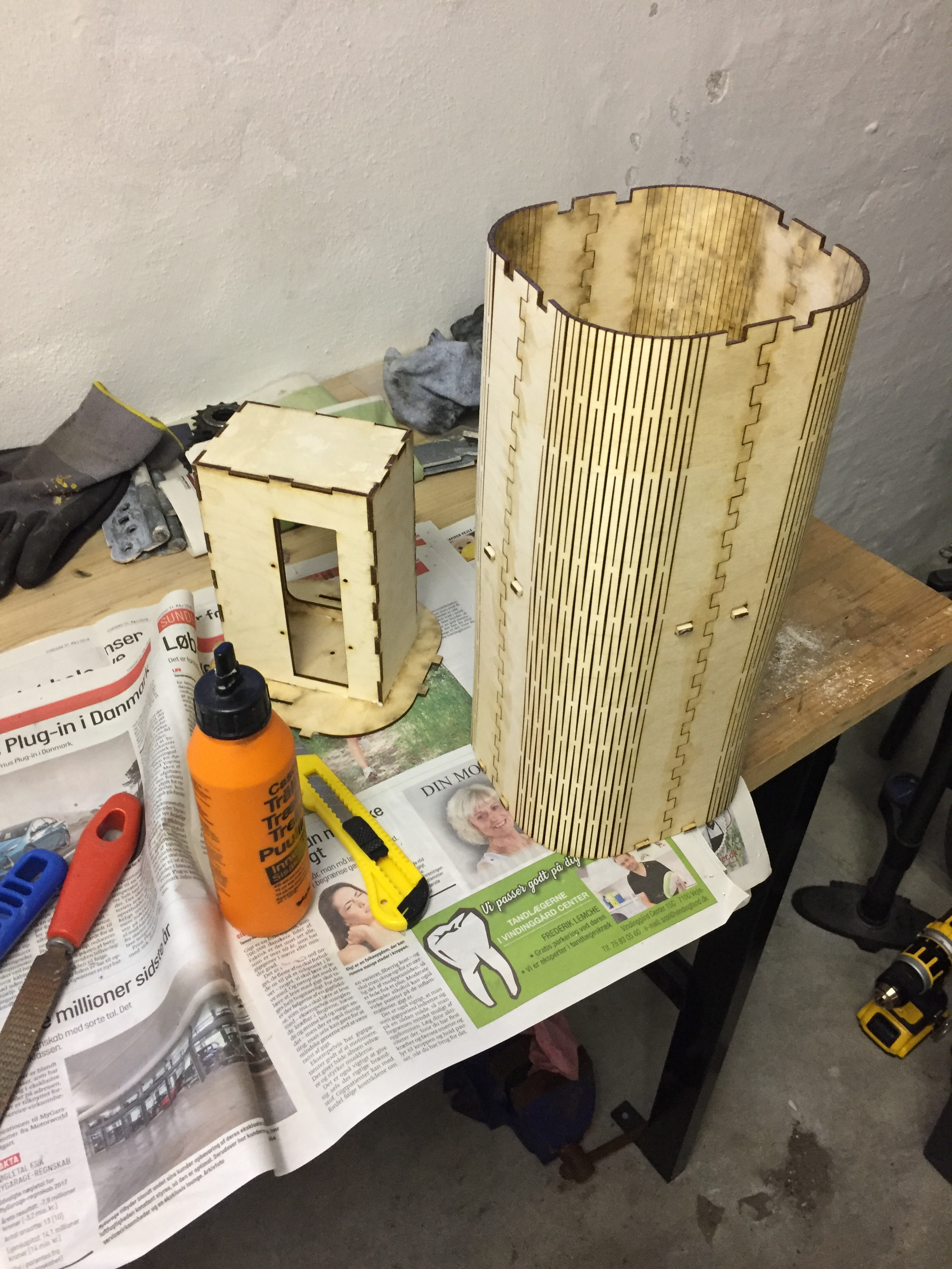
The process is the same when I assembled the lit. I also made a small band made from a guitar strap with some neadels so it would be easy to cary.
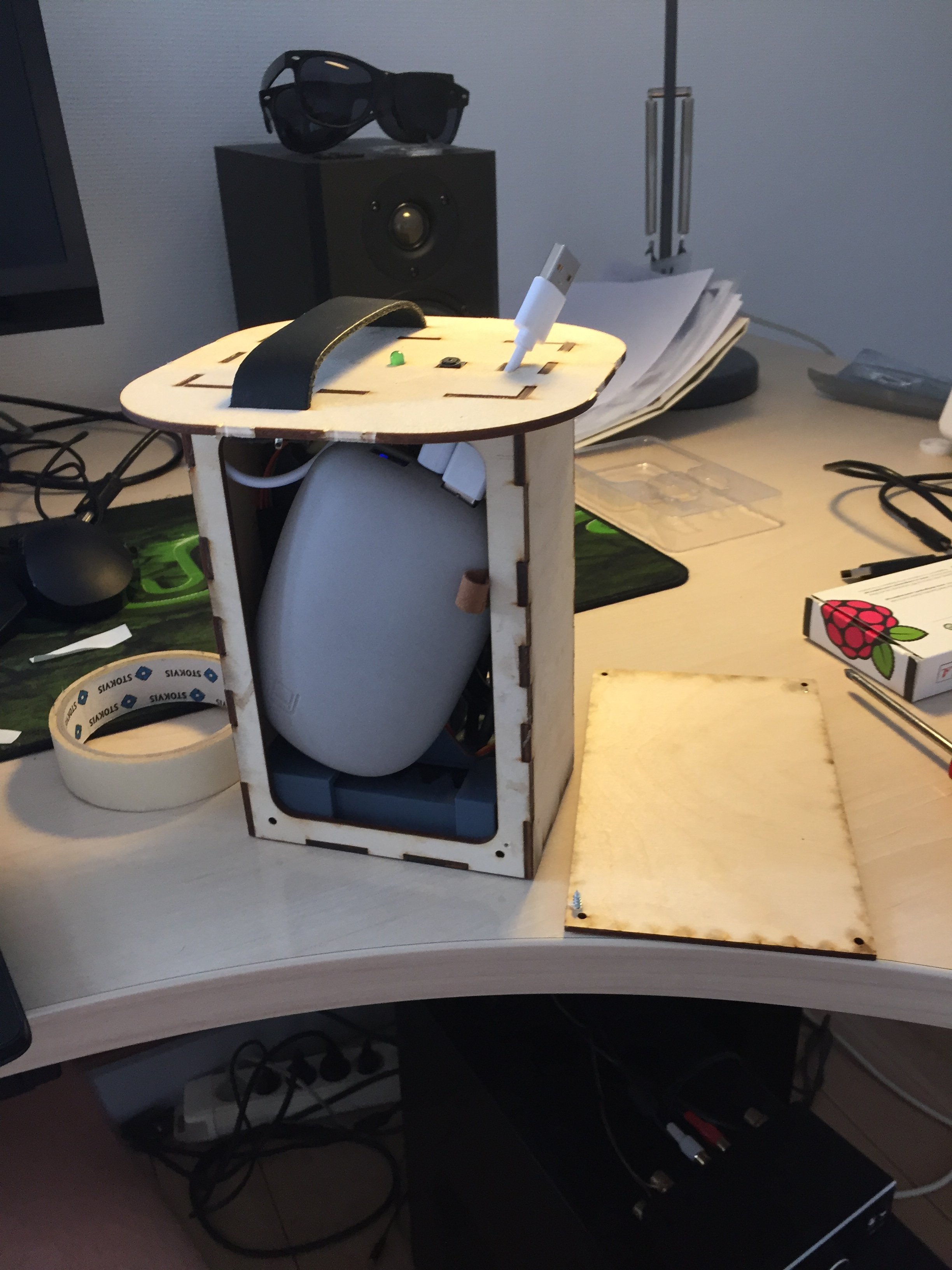
I used double sided scotch to make the electronics stay in the electronics case.
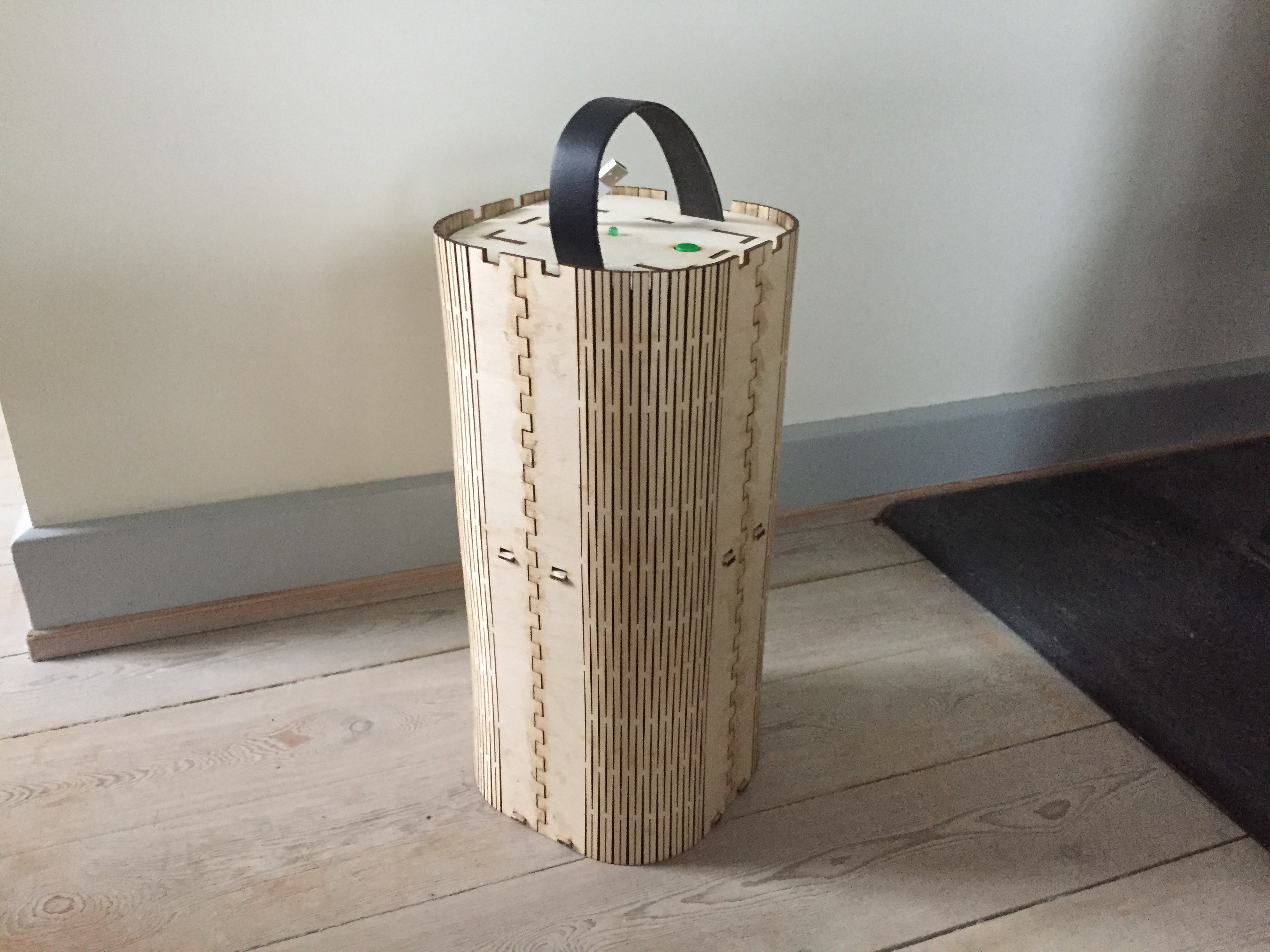
Integrated in the end the this is how my final project looked like:
To see the presentation video and slide go the final project presentation tab(link).
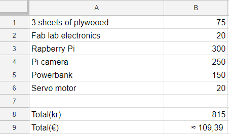
BOM
This is how the bill of materials ended up being like.
To see the presentation slide and the presenation video go the final project tab.