Computer-controlled cutting
Assignment
- Use the vinylcutter
- Account for the lasercutter kerf
- Make a press-fit construction
Files
- Kerf tool
- Game
Vinylcutter
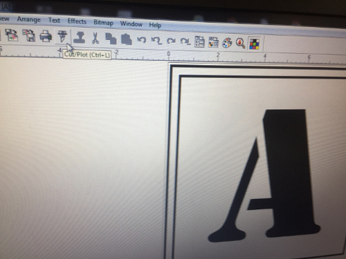
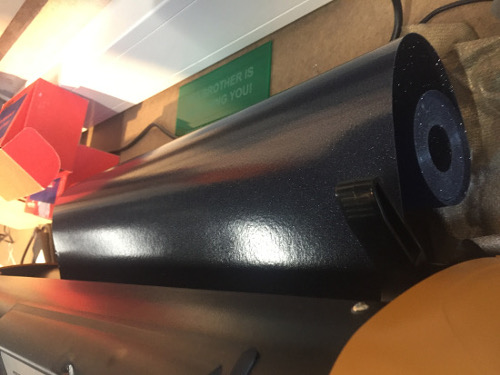
On the vinylcutter I decided to make a sticker that I designed in the previous week when learning Inkscape. Underneath you will see a picture of the design.

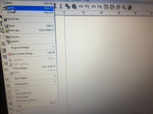
I was introduced to using the vinylcutter since it was my first time using it. First thing is to open the file and pres cut:
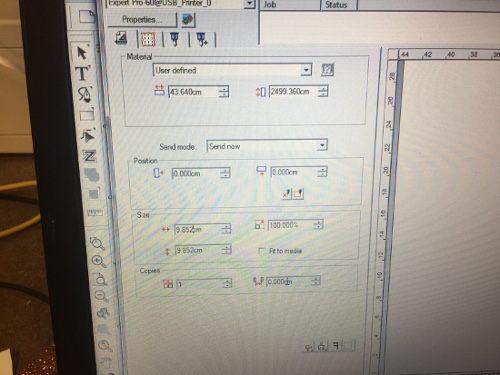
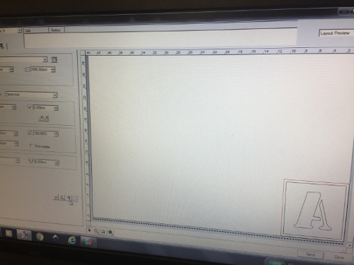
After that a new window opens with a number of settings to select: size, position and copies.
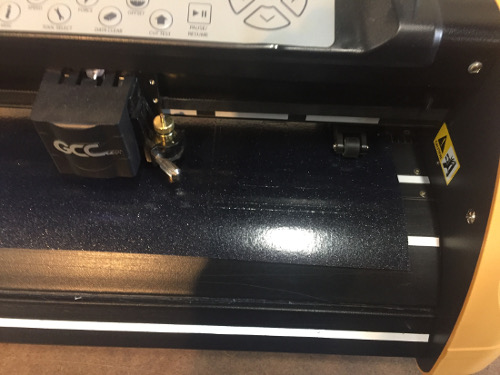
Once the setup is done a role of vinyl is attatched at the back of the machine. The material then go through to the other side. The machine will mark the outline of the job when the up-arrow in the on the machine is pressed. To adjust the z-height if the cutting depth of the machine is not as intended, remove the knife and adjust it with the small wheel.
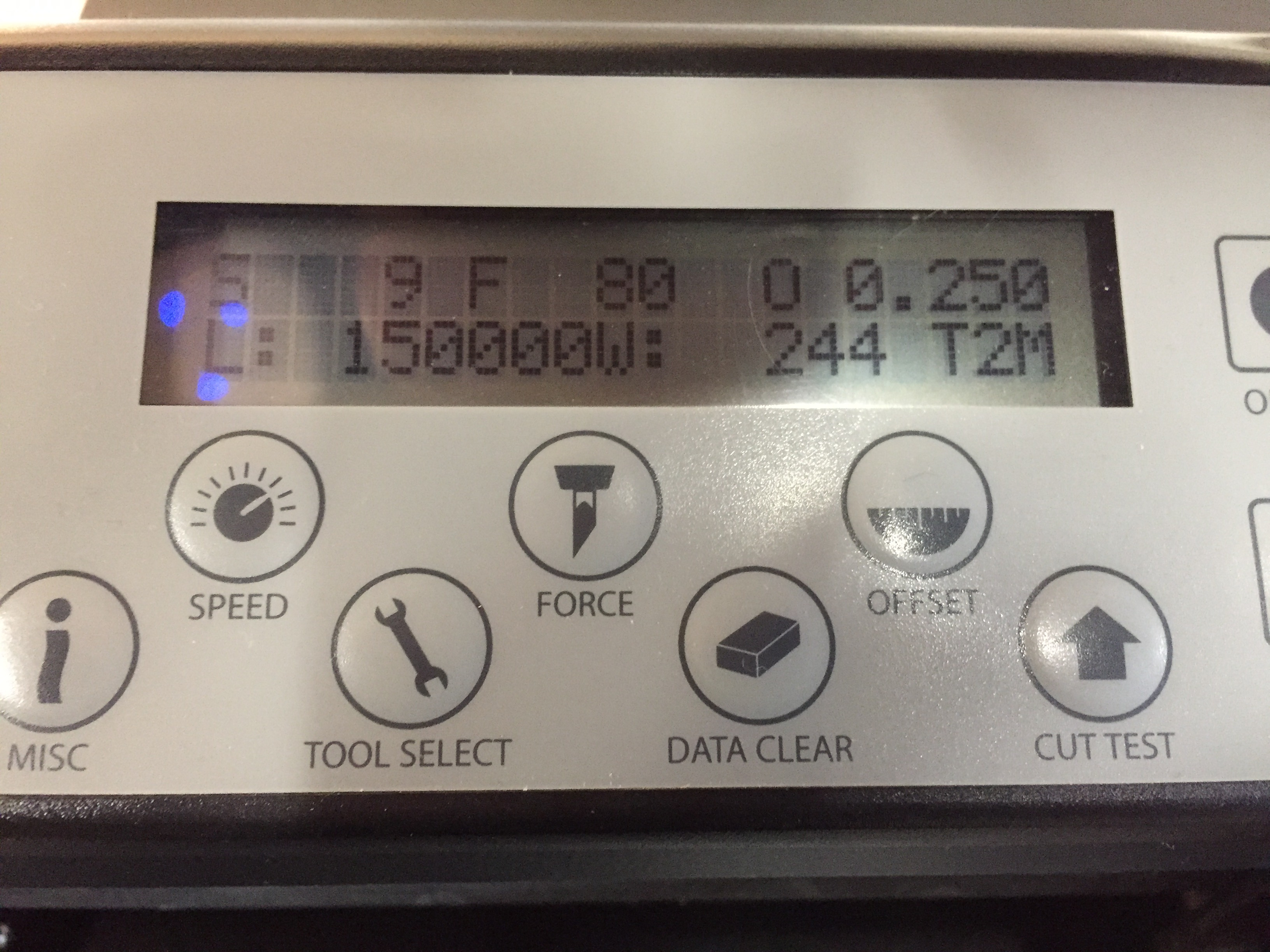
The settings on the machiine itself is the following seen in the pciture, where the main ones are force = 80 and speed = 9:
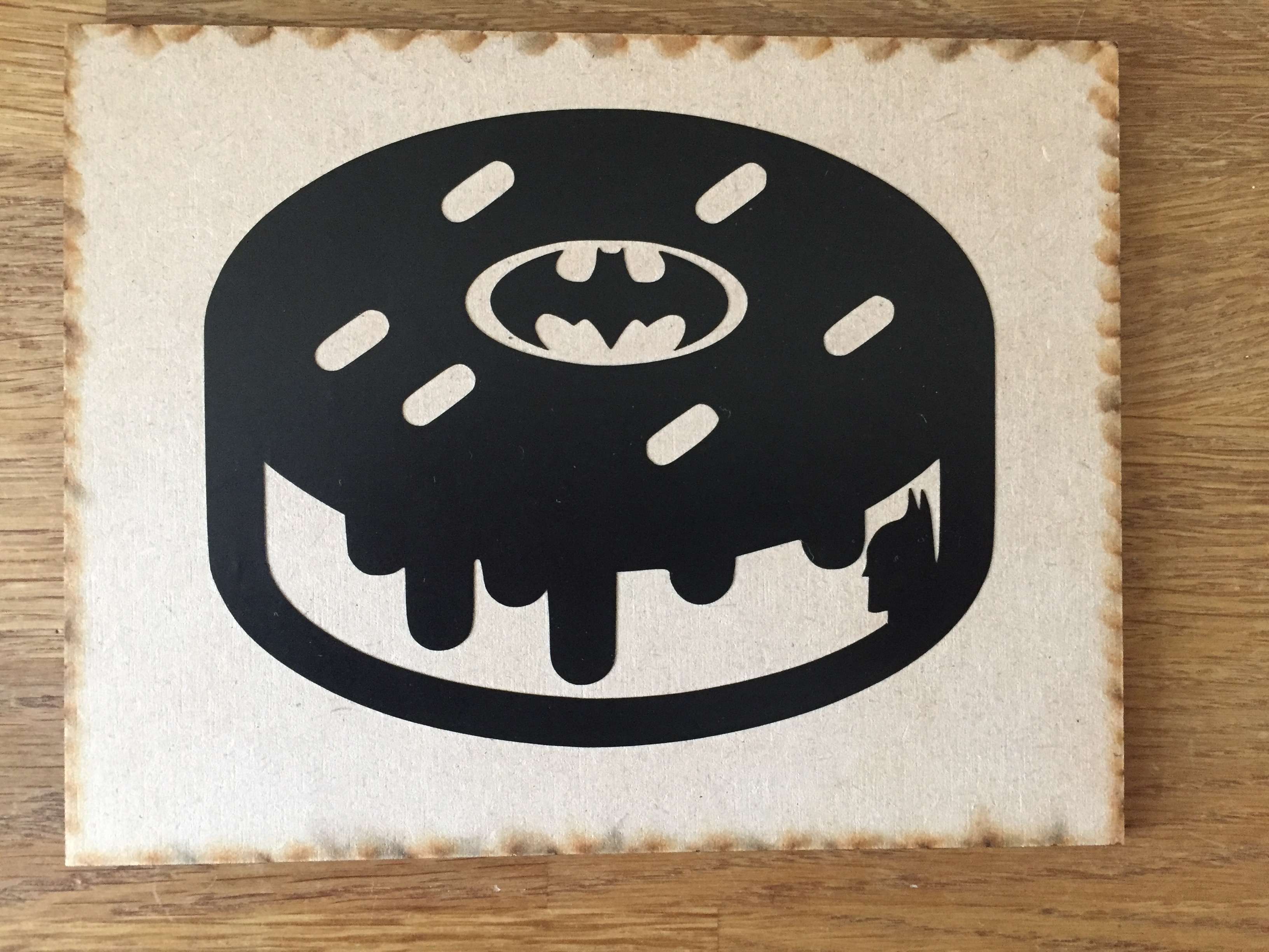
The final result of my design:
Setting up the laser
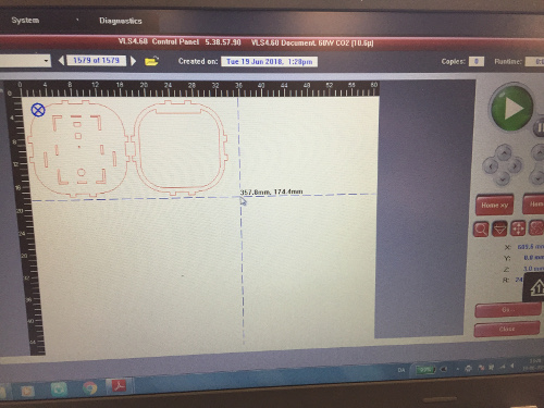
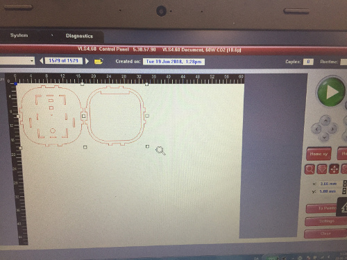
For setting up the laser in our lab the first thing you would want to do is to open the PDF file press print which will import it to the laser cutting software. Once it is in there the point tool from the left menu should be chosen to move the laser around to see if there is space enough for the job on the chosen material. Remember to open the lit of the laser while doing this, else it wont show its pointer. Once this is done select the next tool in the line menu and select a corner of the job which is being moved to pointer with the "To Pointer" button.
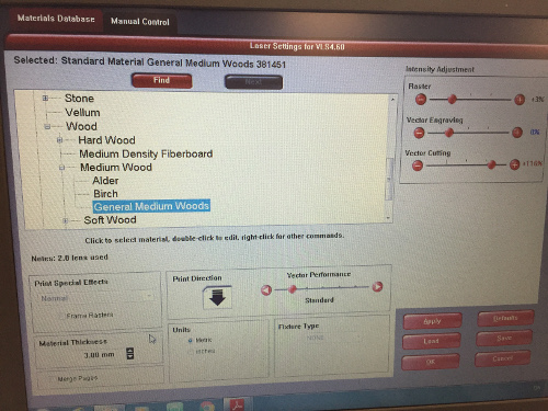
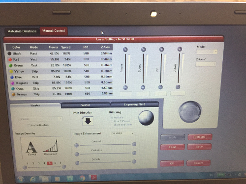
Next there will be a menu like the first picture underneath. Here press go to material database and pick a material and select the thickness of it by measuring then press apply. This is just a database with a bunch of presets to make it easier to do the fine adjustments afterwards.
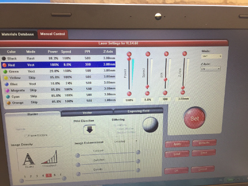
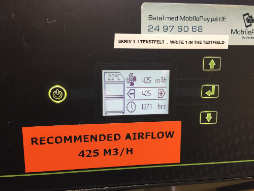
After that we should go to manual control and do the specific settings. For the red colour I have inserted the standard setting we use in the lab for cutting 3 mm plywood. Once this is done press apply and ok and it will take you back to the first menu where you would have to press the big green button to start the job. Before doing this remember to turn on the ventilation.
Lasercutter Kerf
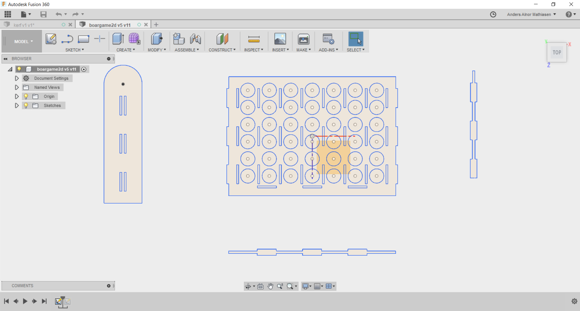
In order to account for the kerf , the diameter for the material that the lazer itself cuts away, I started by making a parametric model in Fusion 360.
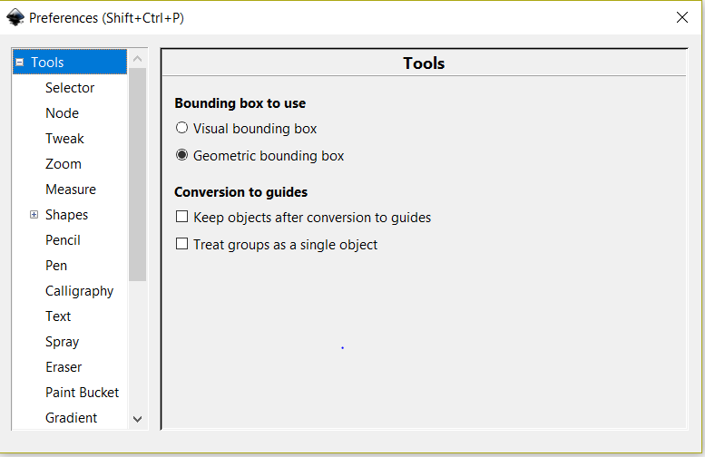
Before I cut anything out on the lazercutter, one of my fellow student was kind to point out to me that I had to change my settings to geometric bounding box so that the file would be read as the lines having no thickness. Something that I was unaware of. The settings for the lasercutter I used in my fablab with Inkscape, was to make the width of the line 0,025 mm and the line color all red when cutting and all black when engraving. For the cardboard of 4.2 mm I used, the speed of the laser was 100% and the power 12% but this depends on the material being used.
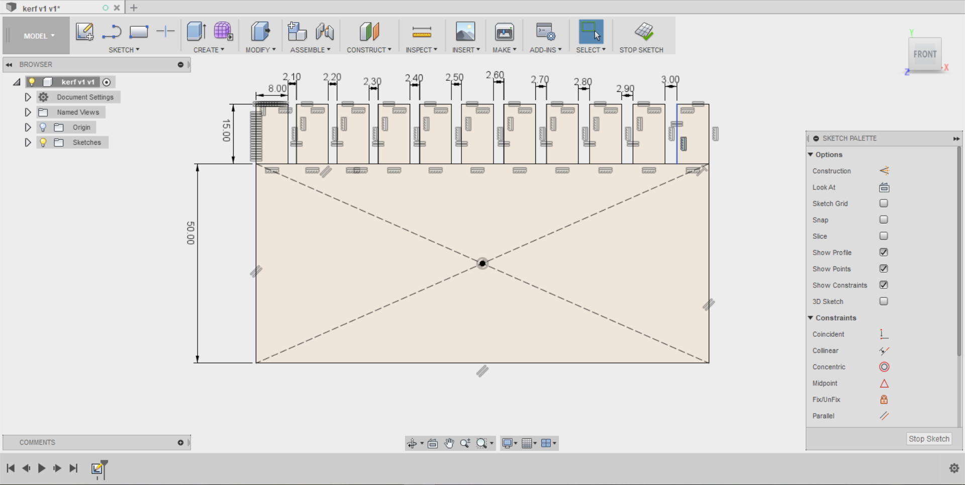
The parametric model enabled my to quickly change the measurements of the model when needed. The material I decided to use was cardboard since it was the same material that i was going to make my pressfit model in and also because it is a cheap material and therefore good for prototypes and testing. I measured the thickness of the cardboard that I would be using to 4.2 mm but I also realized that the quality of the cardboard wasn't perfect, which meant that the thickness was uneven. Below you see the result of the kerf measurement.
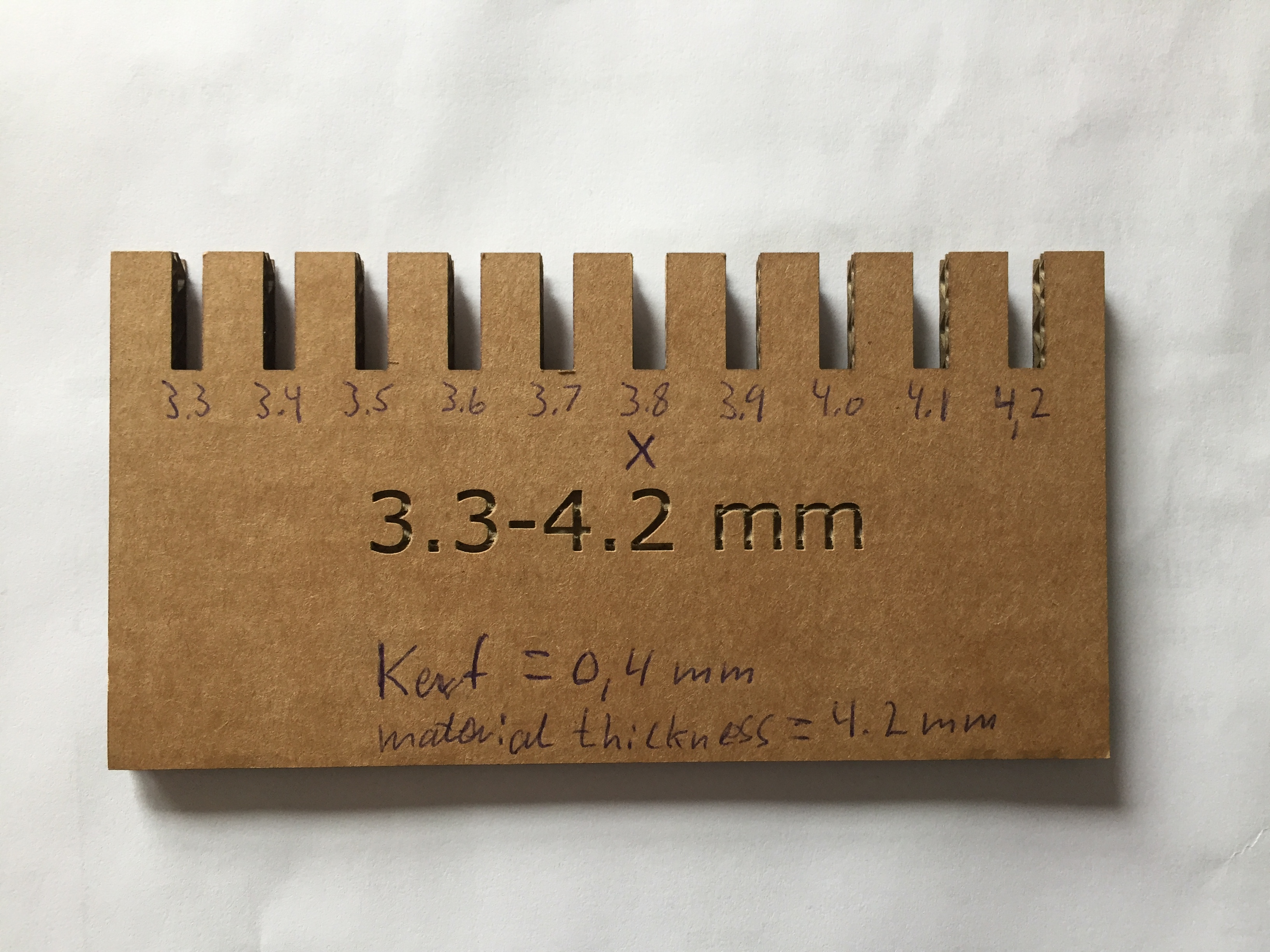
The 4.2 mm cardboard that I had would fit best intro the 3.8 mm slot, which meant that the kerf was 0.4 mm. I would therefore have to add an additional 0.4 mm of material in my pressfit construction for the material to fit in the holes by making them only 3.8 mm wide since the lazer would cut away 0.4 and therefore making them 4.2 mm.
Press-fit construction
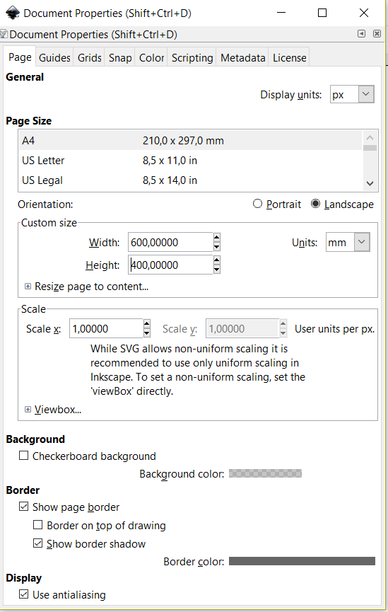
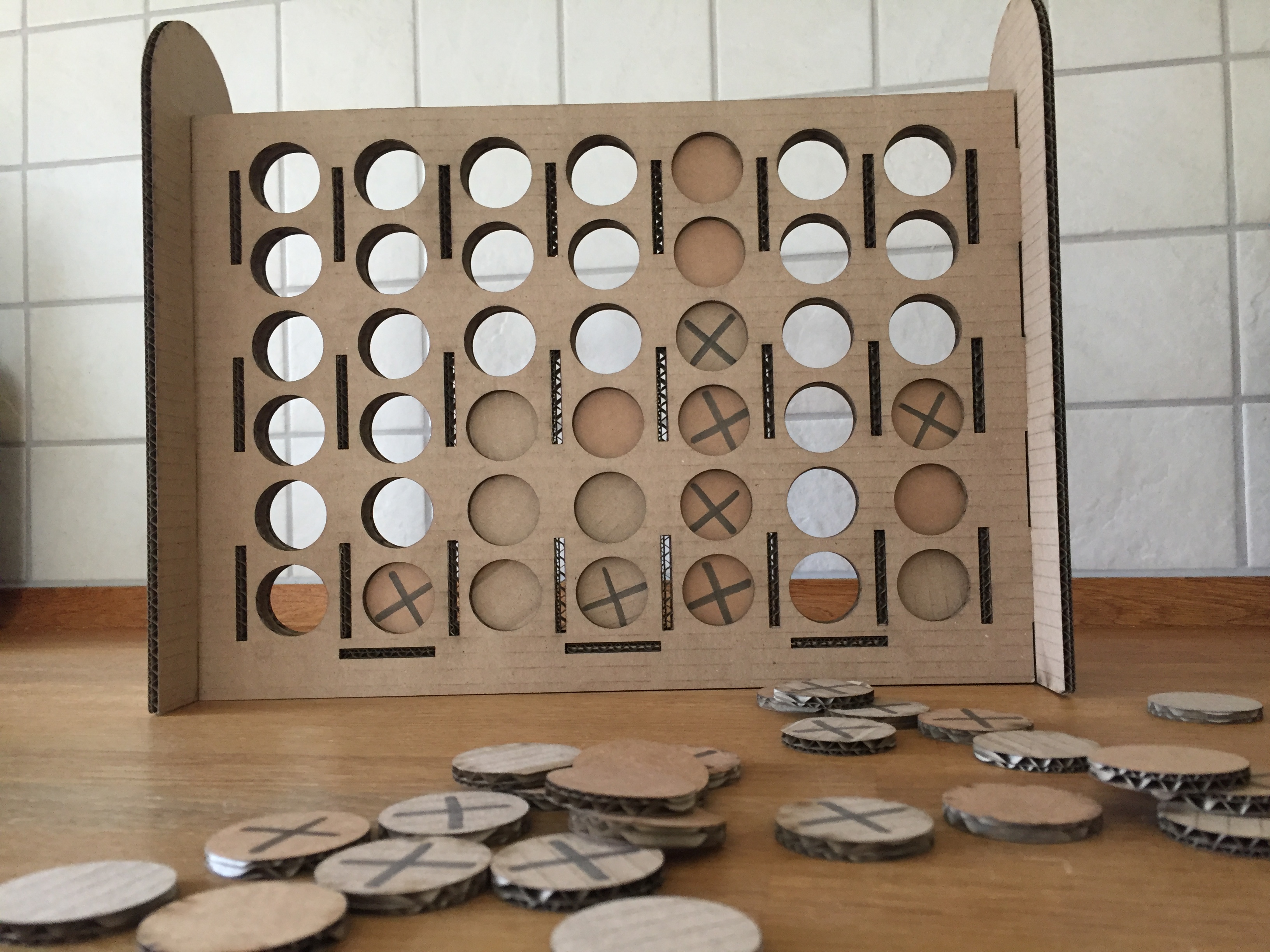
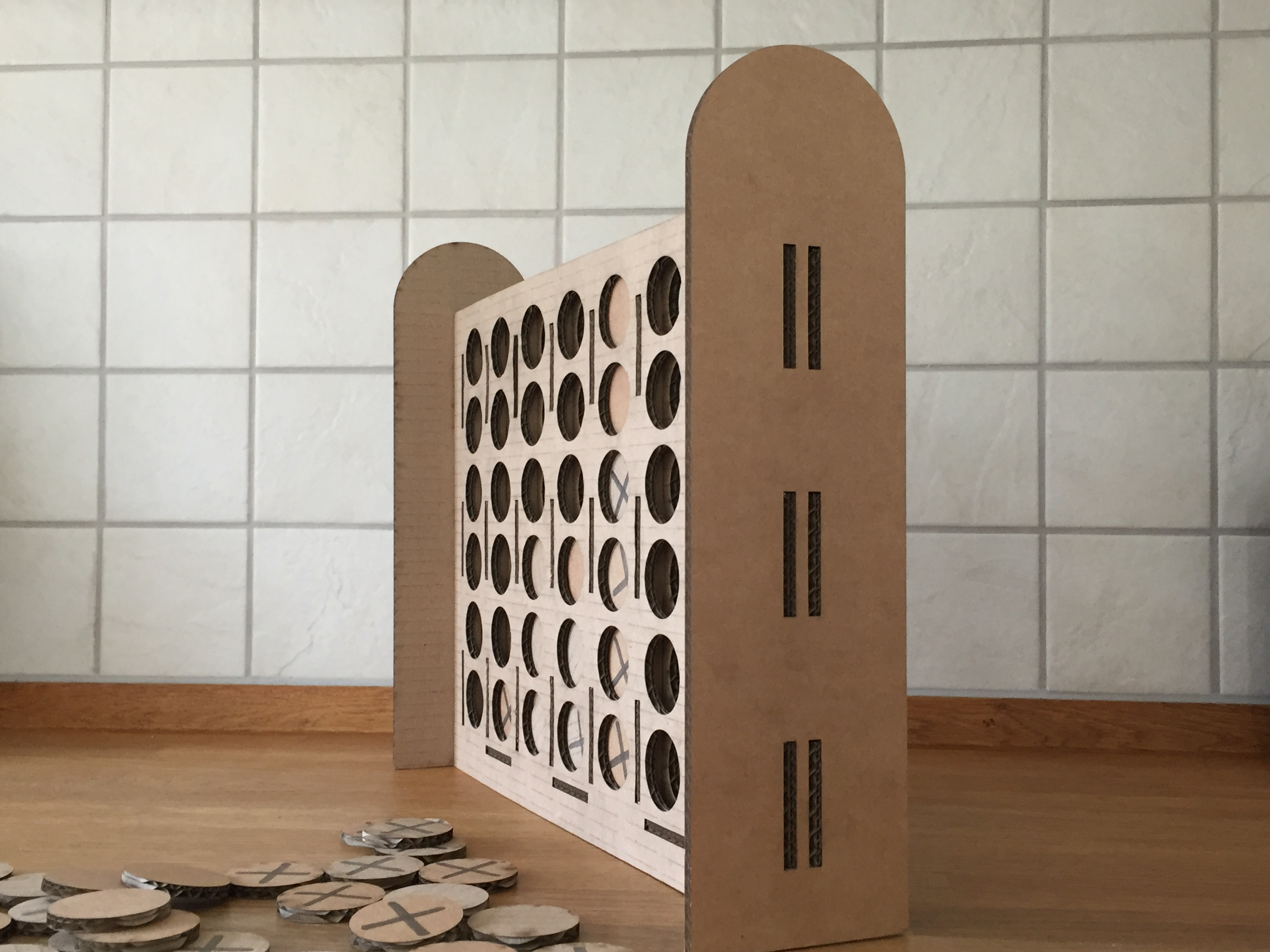
Last week I made a model of the game four in a row in Inkscape. To make it parametric I made this same model in Fusion 360. I made a mistake in my first try by writing all the dimensions over and over again which made me unable to change the dimensions all at once. I solved this problem by using the equal option in the constraints menu. This became very important especially when it came to testing the different parts on the lasercutter where I had to make more than one try to get it all right. As a result of my boardgame being bigger than an A4 paper size, I would change the page size to 600 x 400 mm, which is the size of the bed on the lasercutter. This allowed me to fit multiple items when exporting my file to PDF from Inkscape.
Even though I had accounted for the kerf my initial tries did not fit perfectly. I believe the reason for this is that every piece of cardboard did not have the exact same thickness all over the piece. This meant that I made three tries in total starting from 3.8 mm going down to 3.4 mm instead. 3.4 mm was very tight when I had to assemble the model, but it made it completely unable to move once put into place. On another note, In order to for the lasercutter to read my drawing I had made in fusion, I had to copy it over to Inkscape change the color of the line to red and the width to 0.025 mm and finally export the file as PDF format.
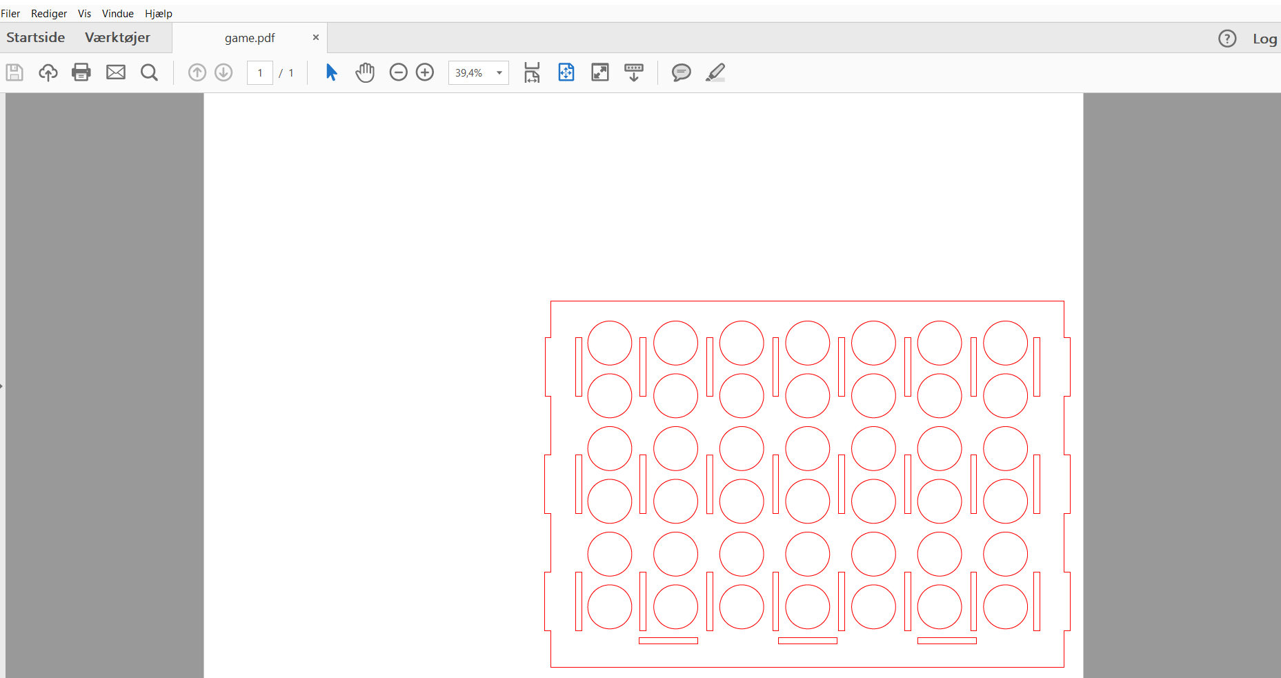
When It came to the pieces that had to be used for the game I also had to make three different types and test them out. On the last size I tested the circles had a diameter of 3.9 mm and they then lined up perfectly as seen in the picture below.
I also spent time using computer controlled cutting in project development week.