Assignment
Individual assignment:Measure something: add a sensor to a microcontroller board that you have designed and read it
Group assignment:
Measure the analog levels and digital signals in an input device
Files
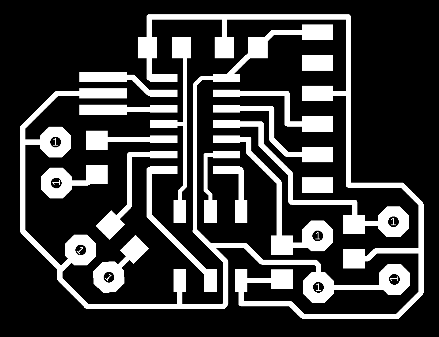
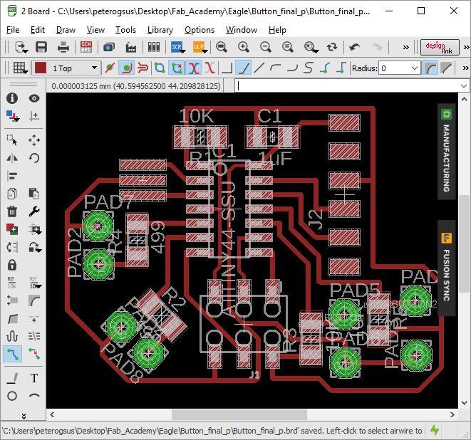
Button:Button_board
Button_schematic
Button_png
Outline_Button_png
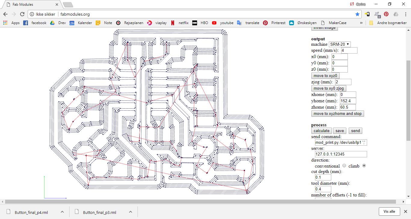
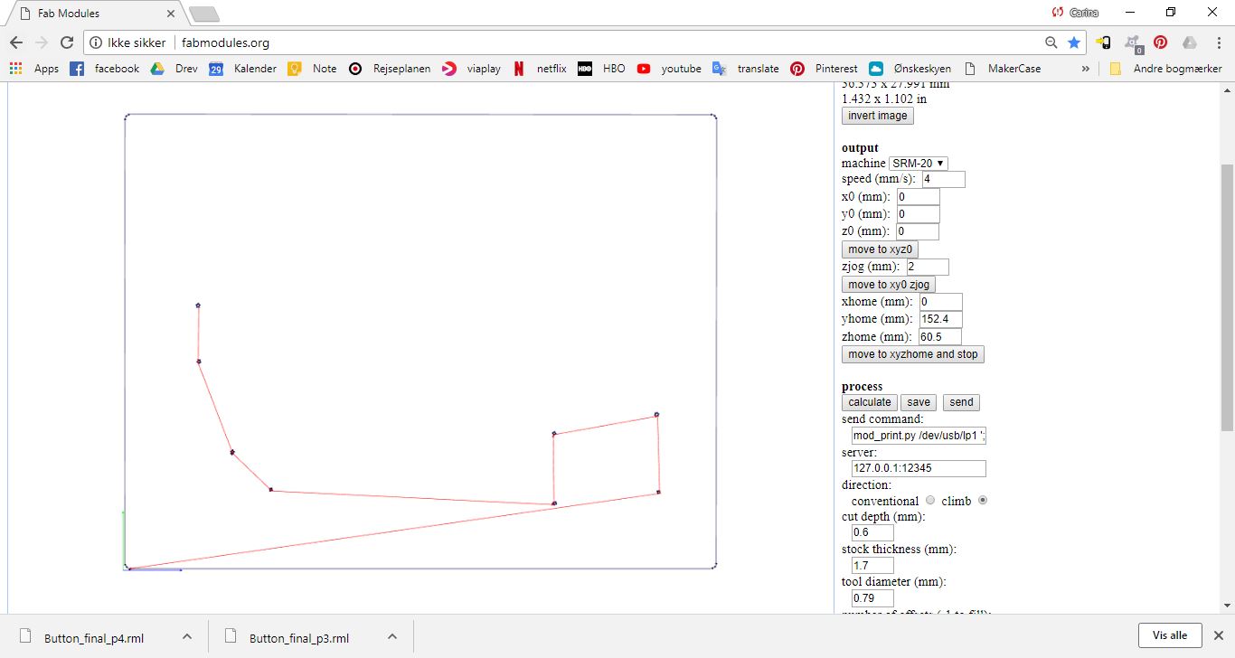
Button_rml
Outline_Button_rml
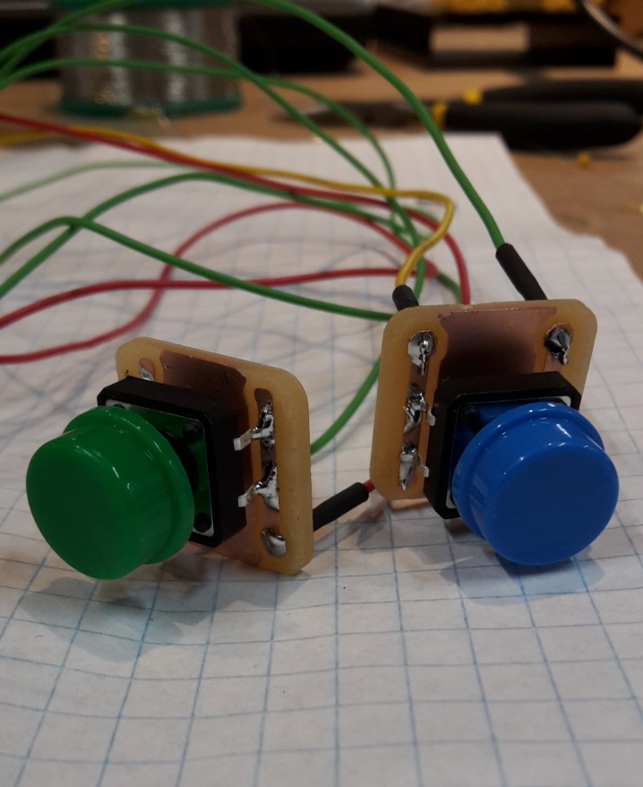
Small button:
Buttons_board
Buttons_schematic
Buttons_png
Outline_buttons_png
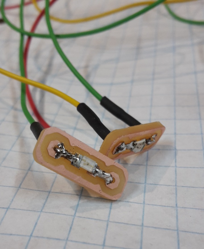
Small LED:
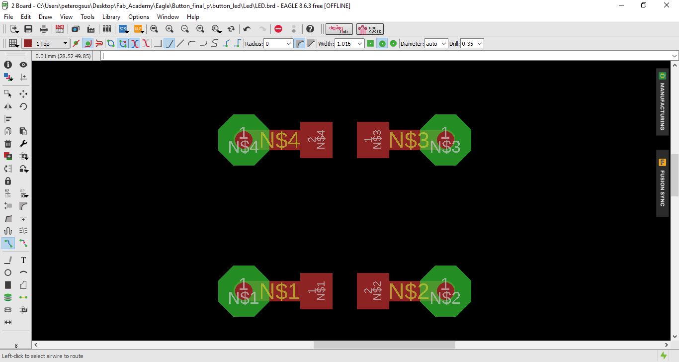
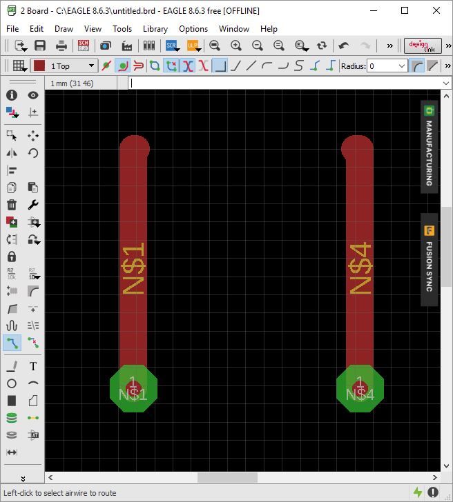
LED_board
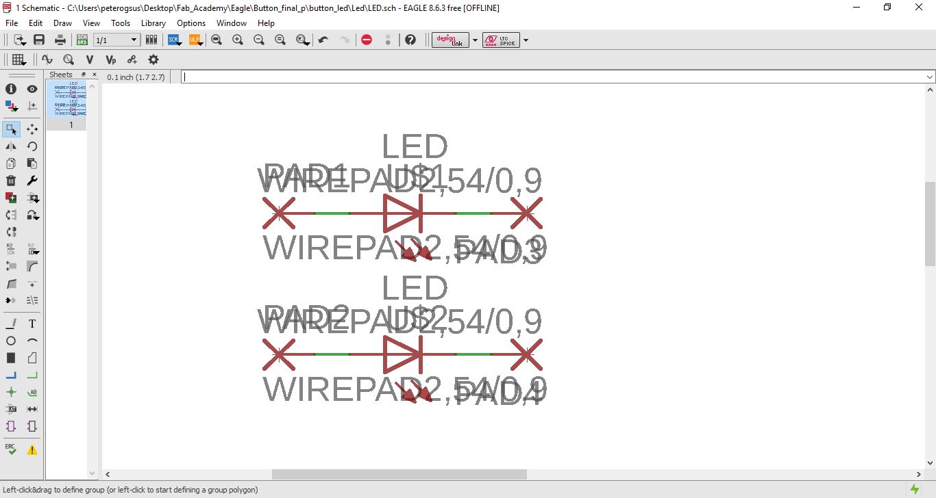
LED_schematic
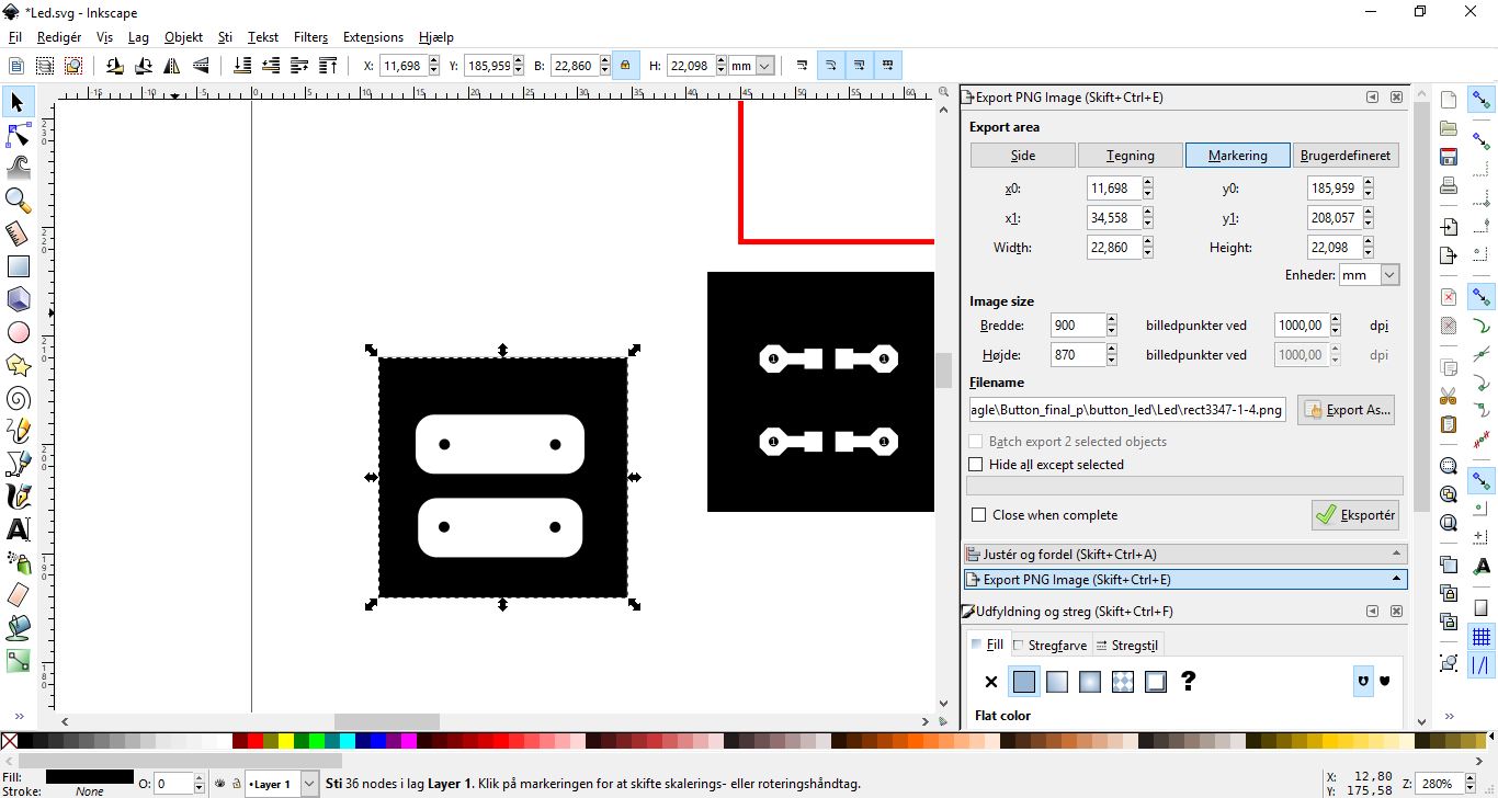
Led_png
Outline_Led_png
Arduino code:
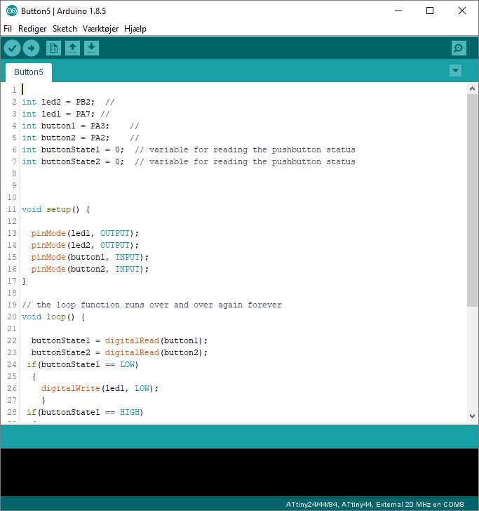
Button5
For the Input I have decided to make a button.
I started out with the hello echo button board that I made. I then added holes for wires instead of having the buttons and LED directly on the board. I have two LED's and two buttons.
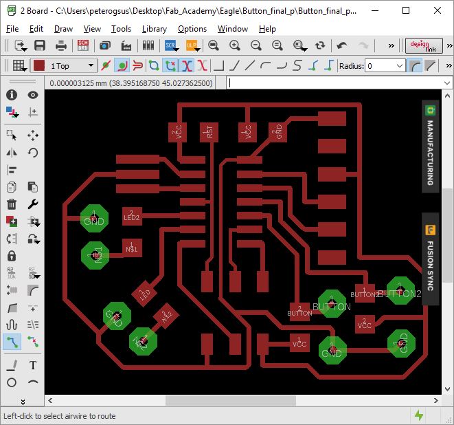
Then I desided to make small boards to put the LED's on.
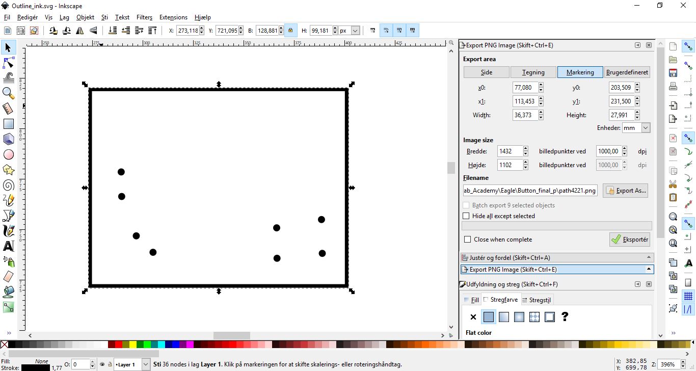
This is the board to put the buttons on.
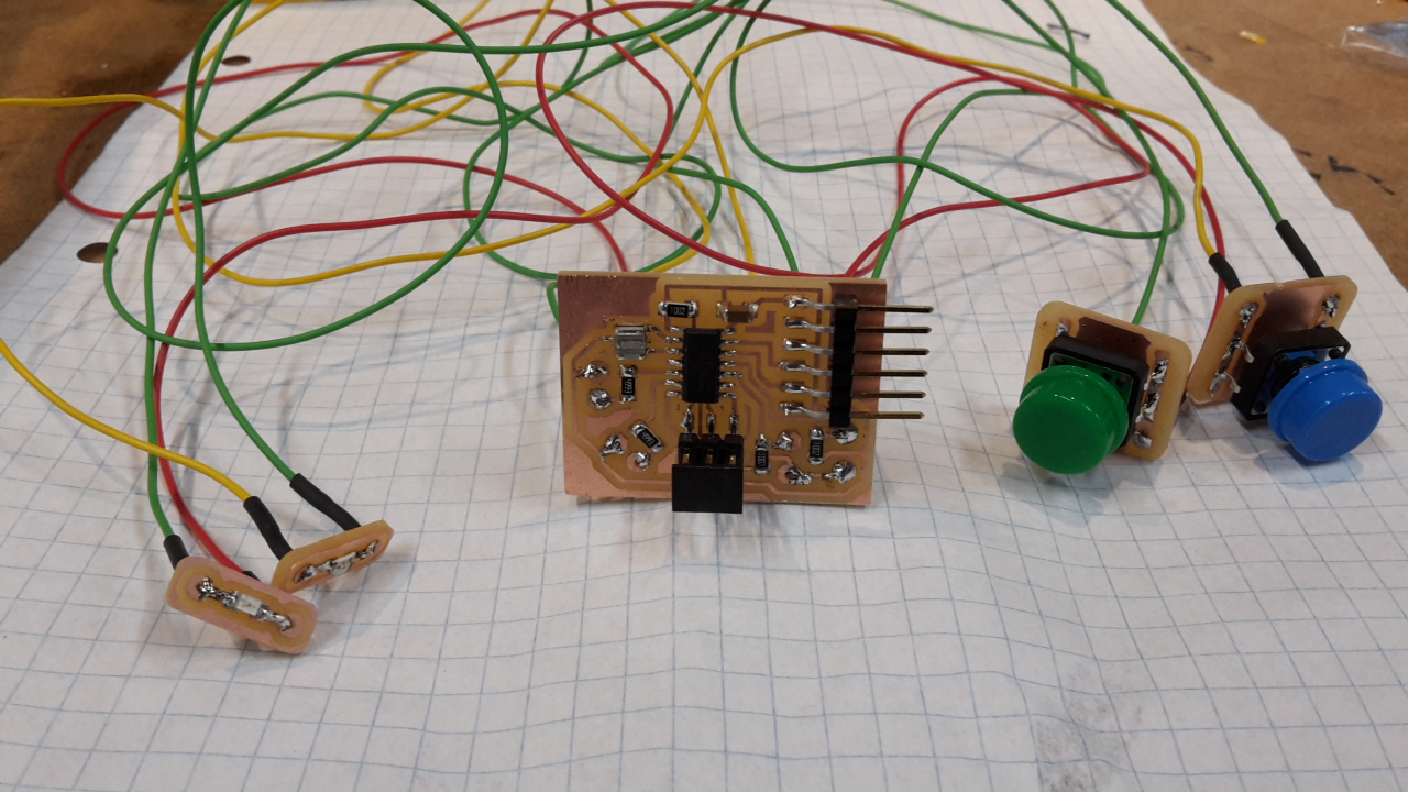
The first board I made (not on the schematics and pictures above) were some of the connections I had made for the wires wrong. At first I tried adding wire jumpers, but ended up making a new board.
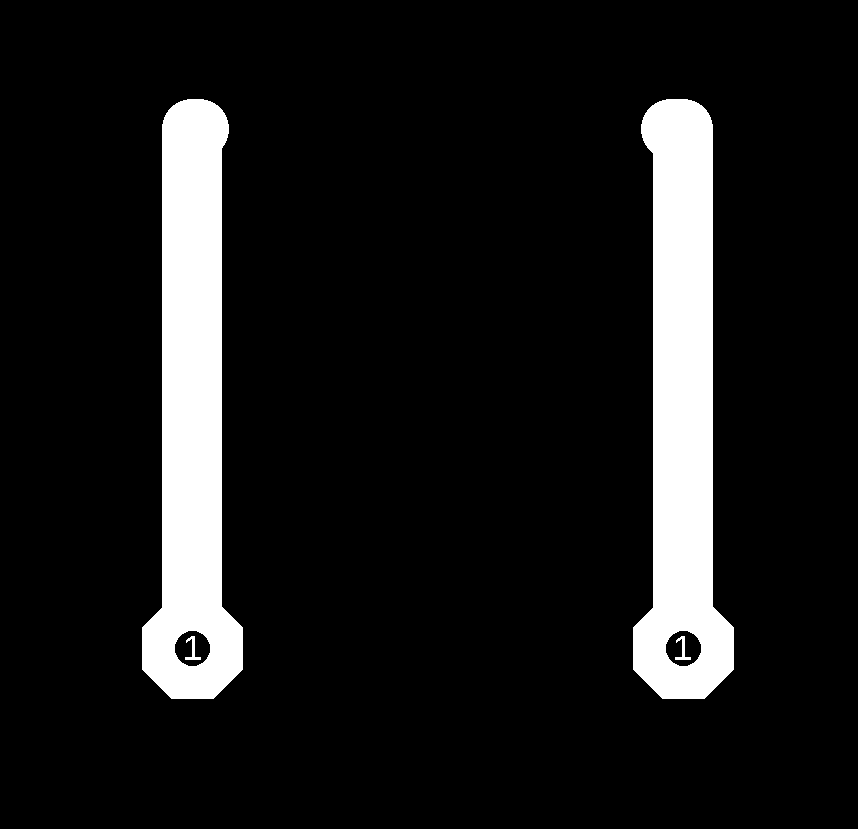
The one on the left is the wrongly made and the one on the right is the done one.
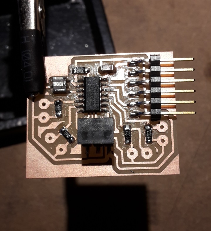
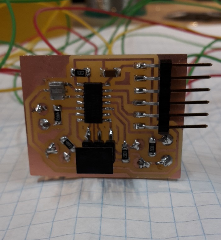
I then burned the bootloader and there was no smoke - succes.
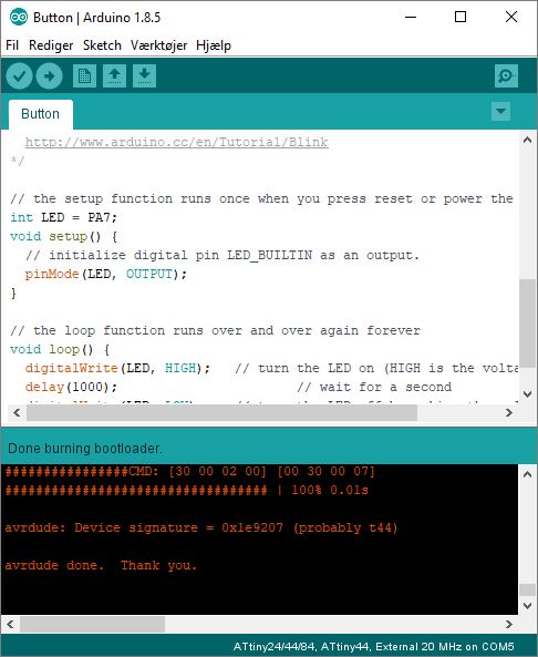
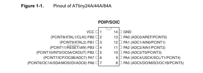
I then look at this picture to figure out what the pins I am using is called in Arduino.
I then tried uploading this code where I am using one of the LED's and one button.
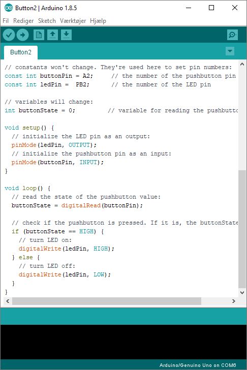
But when uploading the code, nothing happens...
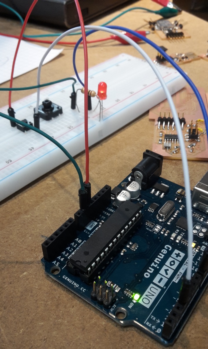
I then try it using the bread board and the Arduino to code with. I am making the same setup as on my button board.
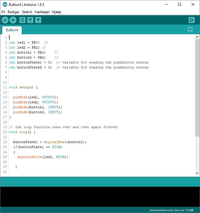
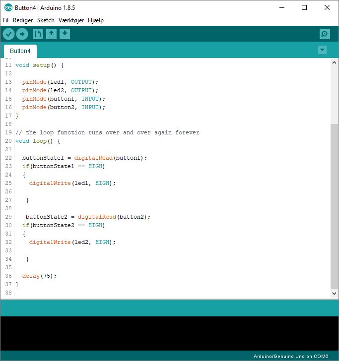
Code
In the beginning I am defining which pin the button and leds are connected to the microcontroller.The buttonstate is 0 because when the buttons are not touched the status is 0 and it will not do anything.
Pinmode: I am defining if the pin will find information or read information.
Input = recieving information
Output = giving information back
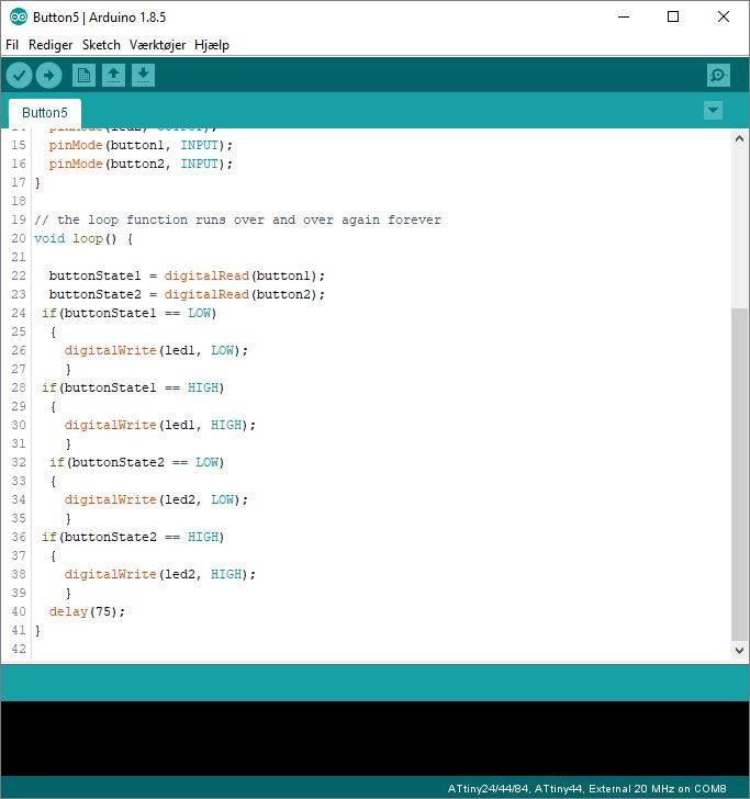
loop:
The microcontroller will keep reeding the information coming from the button 1 and then button 2.
HIGH is 1. LOW is 0.
if the buttonstate is high that means that the button is pressed.
if this happens then the led would be switched on.
delay: time before the loop begins again.
This code works really well with arduino.
Debugging and problems
I worked really hard, but during the process I faced a lot of issues. So here is a list.I had the LED in via crocodile clips.
I had the 10K resistor via crocodile clips for the button.
I found out that I had turned the LED's the wrong way. But still after turning them - it's not working.
I then tried with another LED that you can put directly in the board.
I then tried with another button.
Now it worked - the LED would turn off when I pushed the button.
Then it must be something with the button.
I then tried putting the wires different ways next to the (big) buttons legs and found out that there is a connection if the pins are diagonally opposit each other.
So I cut the copper on one side of the button and removed one of the buttons legs on the other side.
It is still not working.
There is no light in the small LED's when I wire it to the board. Only if I use the big one as on the picture above.
But I testet the LED's and there was light in them.
I then tried removing the resistors for the LED's on the board and adding a 220 instead of the 499.
This is still not helping.
The solderings look good so I still have to figure out the problem.
Debugging v2
I found out that the pin PB2 I was using for one of the LEDs were not able to be used for this purpose.But the code is working with the other LED. I changed it a bit, because it is easyer to have the LED on, and then when pushing the button it will turn off.
See video below