Assignment
Group assignmentTest runout, alignment, speeds, feeds, and toolpaths for your machine
Individual assignment
Make something big
Files
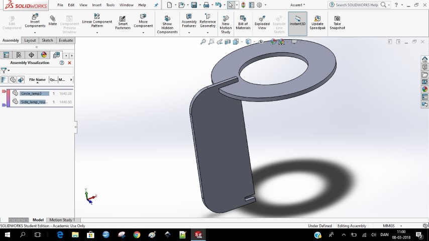
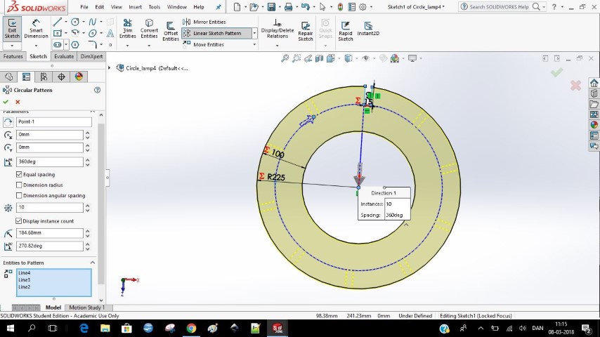
Circle_lamp4Circle_lamp4_bottom
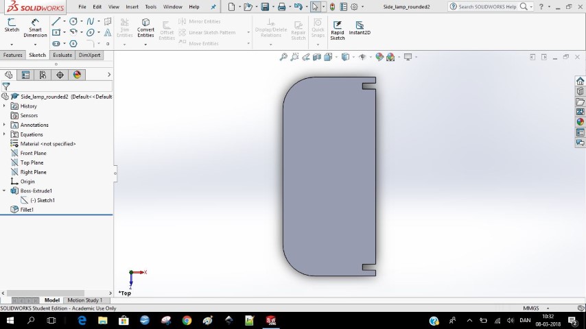
Side_lamp_rounded2
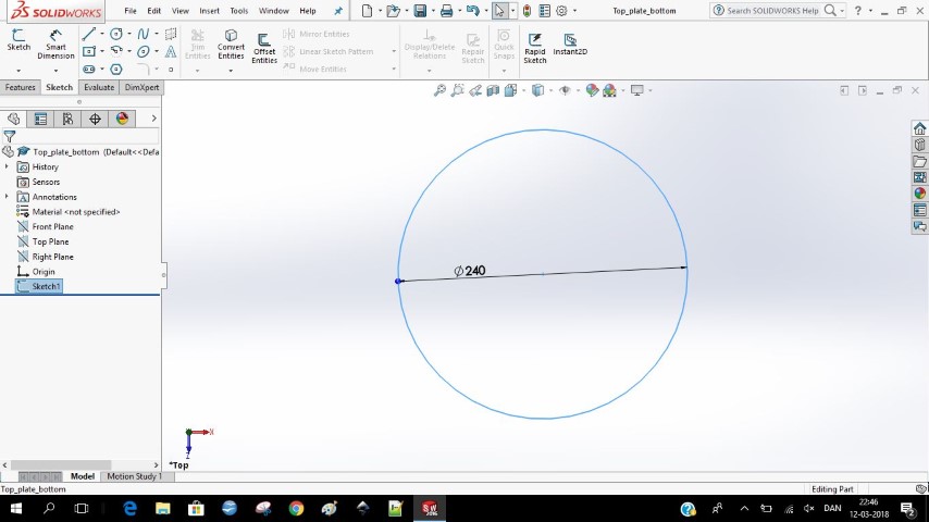
Top_plate_bottom
Top_plate_top
Ideas
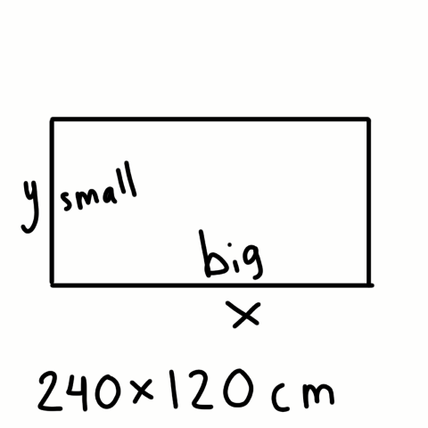
I have been working on a lot of different ideas for making something big. I thought about making a shelf system that could easily be changed (see sketch bellow to the left). First I made a box that would be assembled to another box with a tap. In this way you could have seperate boxes and assemble them just as you want. I decided that this was a cool method, but I would be using a lot of material because it is boxes on boxes, so it would have double walls some places.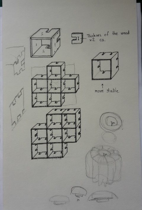
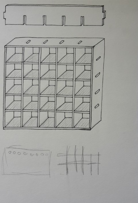
Another idea I had was to make a big shelf system you could also modify (see sketch above to the right), but in this one I would use longer pieces but I would be able to make them in different lengths.
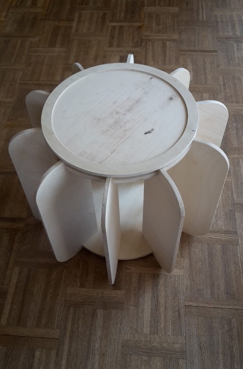
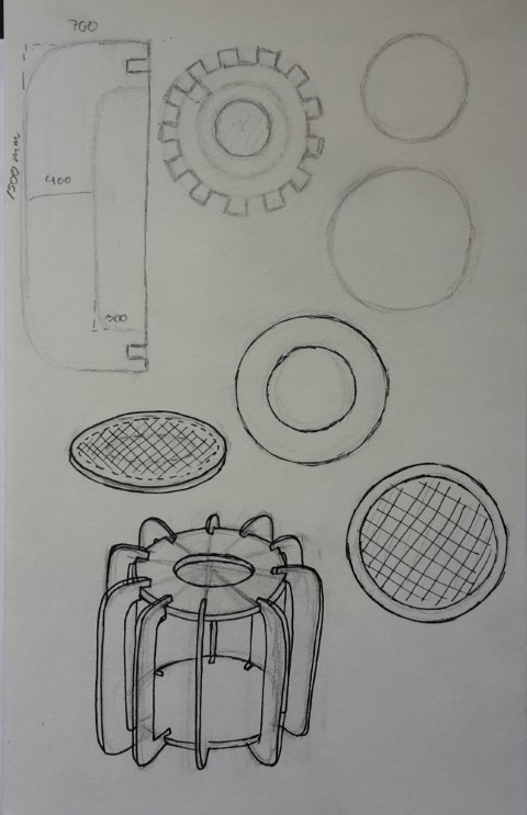
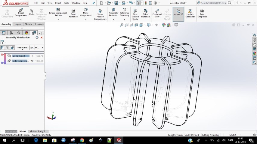
I decided to make the lamp I made for pressfit constructions, but I modified it. Instead of it being a lamp it is a multifunctional stool/table. When you have the pillow on it’s a stool and when you don’t it’s a table. You can also lift off the table plate and fill the “lamp” with pillows or blankets and put the lit back on.
Designing
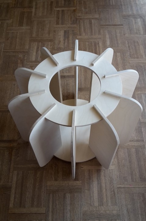
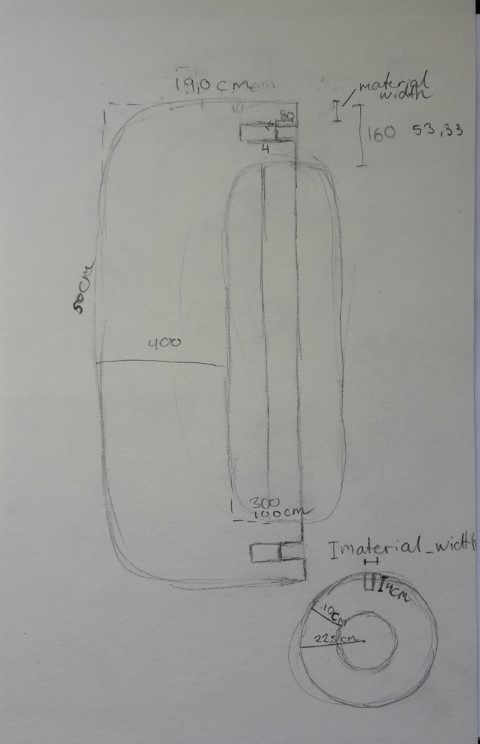
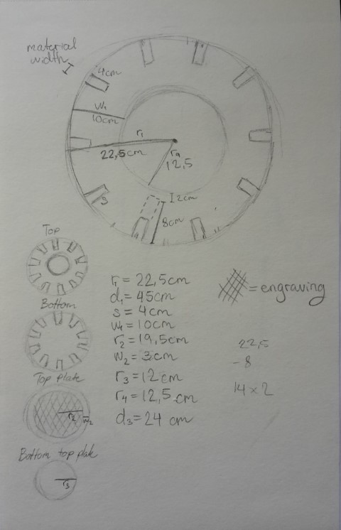
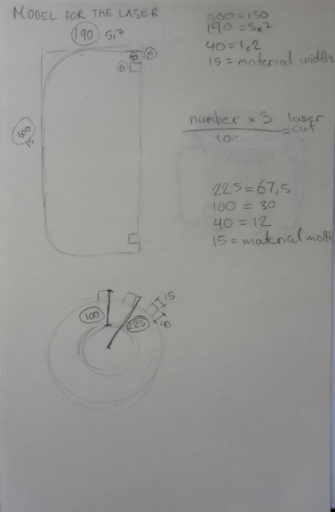
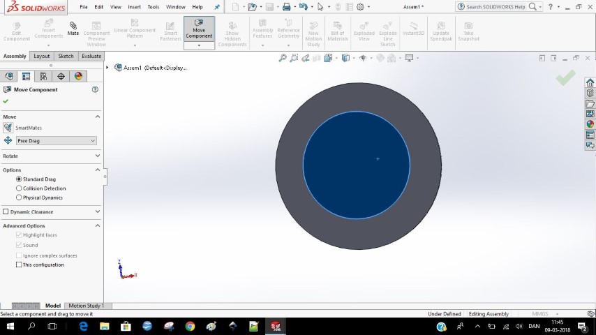
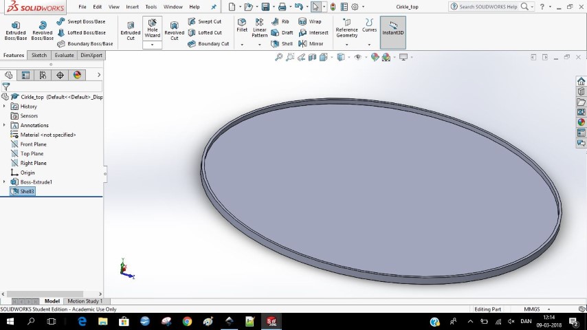
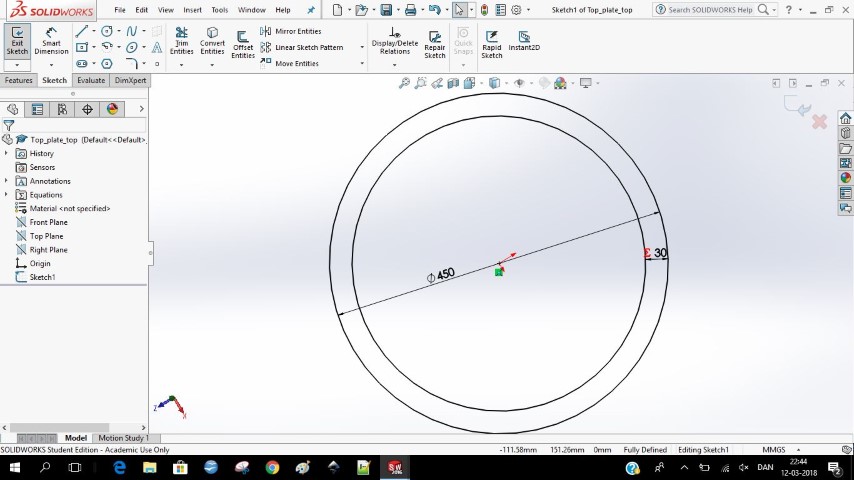
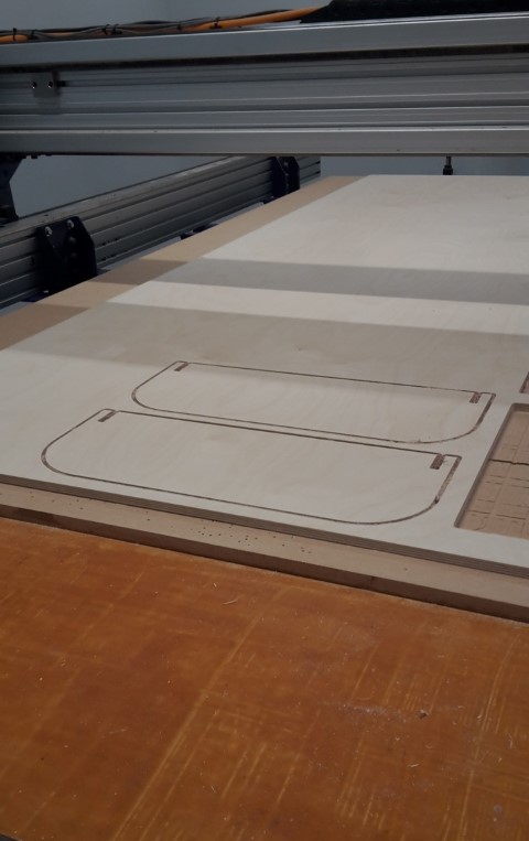
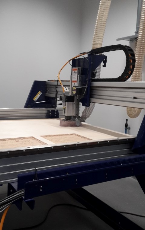
I took the drawing I made for the pressfit lamp and saved one of the files with a new name so I wouldn’t edit the old file. For the pressfit top and bottom I made a whole new circle because I wanted to have less sides than on the lamp. It was easier to make a completely new one instead of modifying the lamp version. I made it all with parametres so it would be easy to change. I made a lot of equations for the lamp on paper because it needed to fit exactly together. I also made an extra pair of equations because I wanted to make a small model on the laser before I would make it on the CNC machine. I saved the files with another name so I had both the big version and the small version.We went to Odense FabLab to use their CNC machine. Because my project is so big, I wanted to make a test to see if the pressfit would fit. I made two of the sides to test the pressfit. It was very tight so we turned down the threshold I think. But I don’t think the threshold was saved in the settings because when we milled the whole thing it was very very tight and might need some sandpaper. We milled it without tabs and used a downcutting tool. The downcutting tool is pressing the shavings down in the drilling line. In this way the thing you are cutting out is staying down because of the material in the line, it is in tension. This was the way they did it in Odense, but they also said that if it was small things, you should add taps when using the downcut tool.

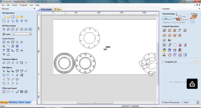
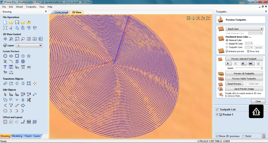
Vcarve
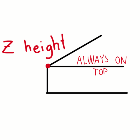
In our lab we use Vcarve to make the files for the shopbot.In FabLab Spinderihallerne we set the Z on top of the plate because we have an aoutomatic zero button. The button does the same as if you were doing it manually. The drill will send curent through, so it can feel when it is touching the button, and at which height.
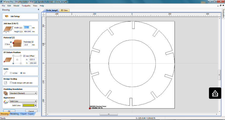
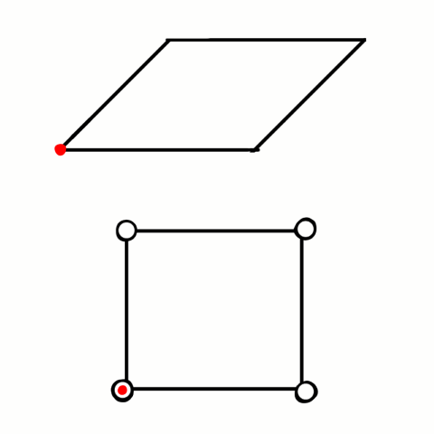
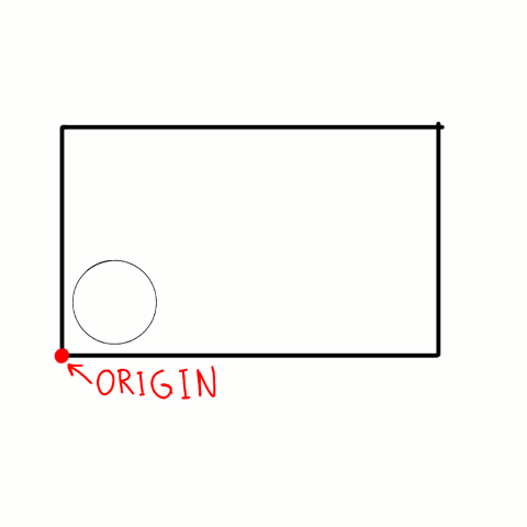
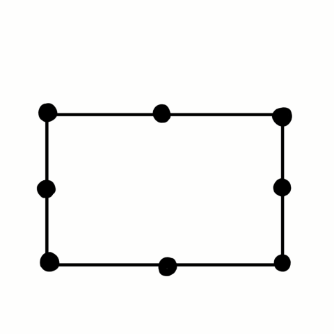
XY datum position:
It’s important that it is in the corner as shown on the pictures. Otherwise the machine sometimes might think that the thing you want to cut is actually outside the plate that you want to cut.
We don’t use the offset button. It is easier to do it manually. Remember to make space for screws.
Units:
Remember to make it metric
mm not inches.
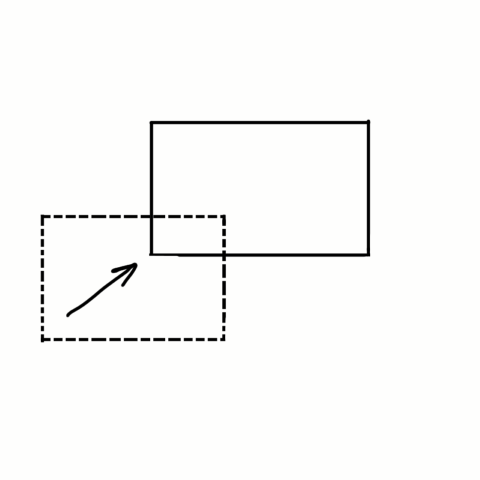
Move selection:
This will move the position of your drawing
Scissor:
Can cut lines
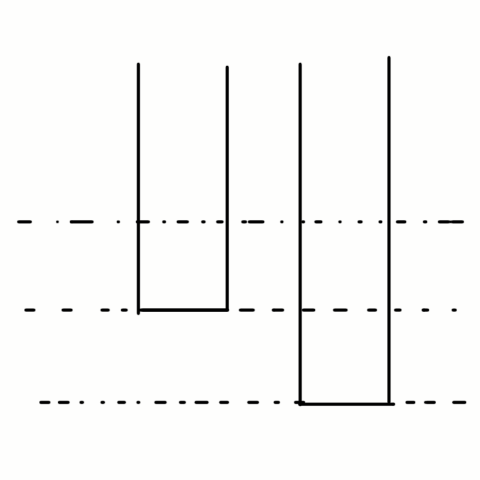
Join Vectors:
Some vectors might look like this if you zoom in.
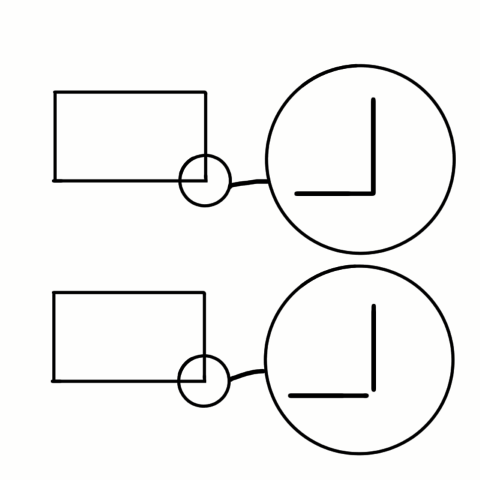
Fast way (top of the picture)
Slow way (bottom of the picture). The machine will go up because it will read the small space, and down again. It’s a default in some programs.
Selected vectors:
Closed:1 - If this is 0 then the line is not closed.
Open:0 - If this is more than 0 it means that there are open lines = not closed lines.
You can only push the JOIN button if there is an open line.
I decide the tolerance between the open lines.
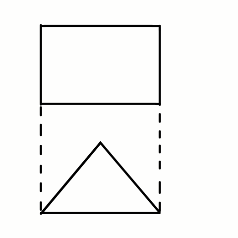
Nest parts:
Moves everything close together.
You can also choose to nest parts inside other parts.
Group selected objects
Material setup:
Pay attention
Choose the right stuff.
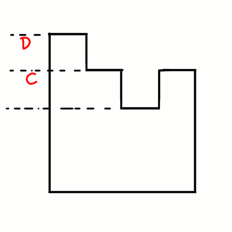
Pocket toolpath:
Start depth(D) should be 0,0 mm
Cut depth(C) - you decide fx 10mm
Different bits:
Imperial - inch
Metric - millimeter
Upcut - throws material up and away you have to have fastened the material really well.
Downcut - presses the material down, the plate will stick better. Use this for ca under 15mm plate.
Clear pocket:
Offset - controventional
Important to check preview.
Passes:
This shows how many times the bit should make a row/levels
Machine vectors:
Outside/right
Inside/left
On
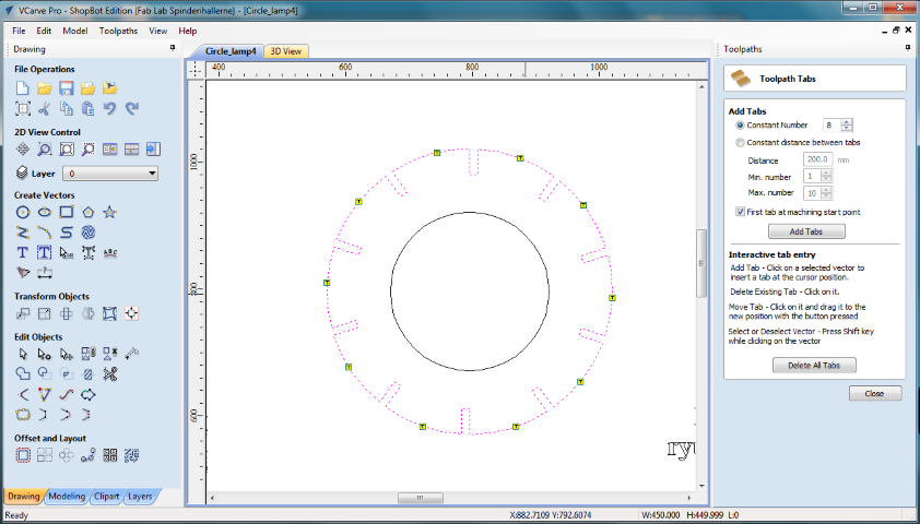
Add tabs:
3D tabs => will make big tabs because the machine just keeps on the speed.
Add tabs -> edit
Constant number => how many tabs you want.
Name it - fx as the bit you are using.
Choose the cut - save toolpath
Shopbot metric
Save toolpaths to file.
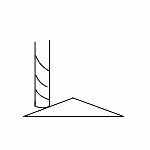
Dog bones
I decided not to add the dog bones in the corners because I wanted it to be a neat design. If I made it with dog bones you would be able to see them afterwards.You can add dog bones in the corners if you want the corners to align. Because the drill is round, it can’t make a complede square. If you want this you have to add dog bones.
There are different kind of dog bones. You can place it on the side or on the center of the corner. The placement is a matter of design.
Chip loads
To understand more about chipload I look at this page where it is well explainedChip loads: Controls the required force to cut the work material.
Assists in controlling heat
Controls tool wear
Directly affects the metal removal rate
Directly affects surface finish.
The chip load is a measurement of the thickness of material removed by each cutting edge during a cut.
This is a valuable piece of information which can then be used to calculate new set ups.
Chip Load=Feed Rate (inches per minute)/(RPM x number of flutes)
Example: Chip Load = 500 inches per minute / (15,000 RPM x 2 flutes) Chip Load=.017”
Feed rate and speed will vary from machine to machine as a result of machine rigidity, horsepower, collet condition, spindle integrity, part clamping, hold down.
Chip loads are based on material thickness of average size for cutting edge length of tool.
Making of
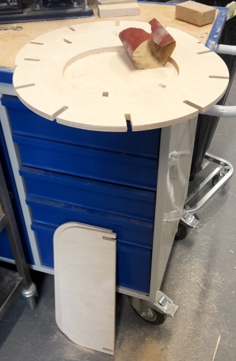
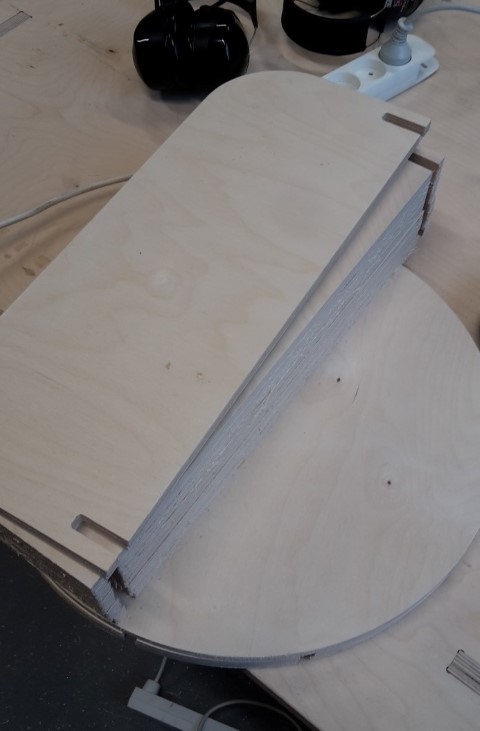
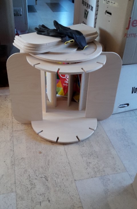
Assembling
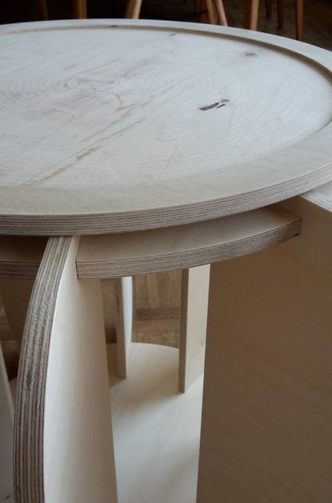
It wasn’t meant to be this tight. When I made it on the CNC I started with making two of the sides to see if it was the correct pressfit. It wasn't perfect, so there were added some offset, but I don’t think it got saved. Because I had a hard time assemble it.I had to use a file in every single pressfit. This was a lot of work, but I was able to get it all fit together (with the use of a hammer). I also sanded the hole thing because when we used the downcut tool, some of the edges were rough.