Machine Design
Group Assignment
- actuate and automate your machine
- document the group project and your individual contribution
Link to our group website:
Individual assignment
My assignment for this week is electronics assembling
Files
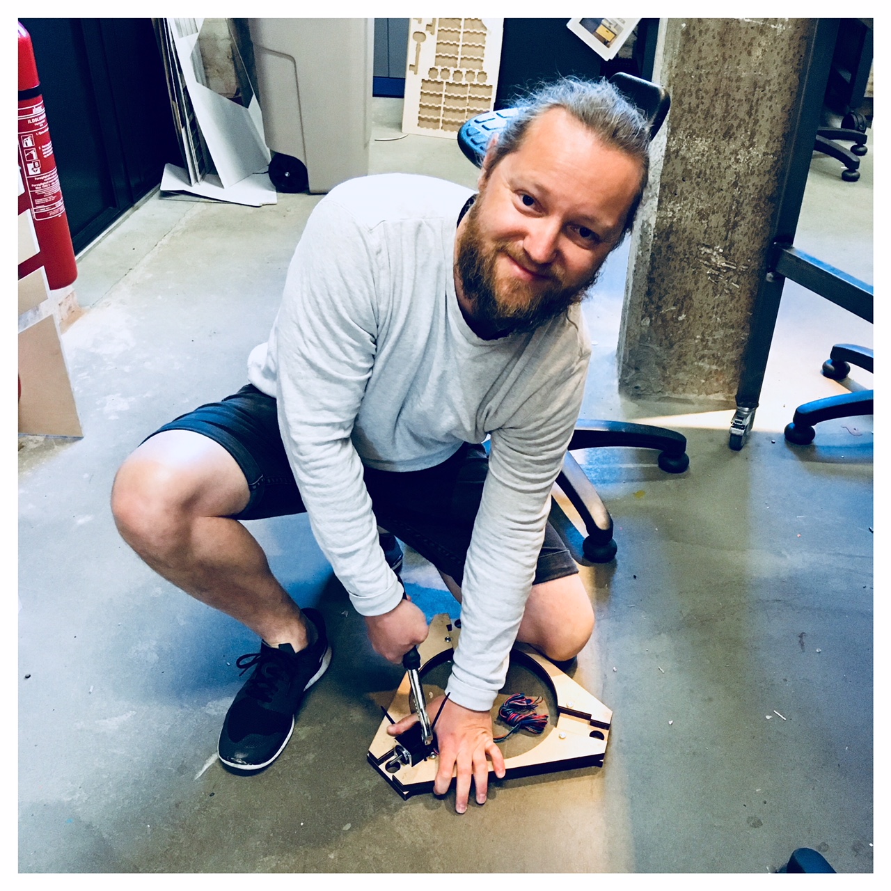
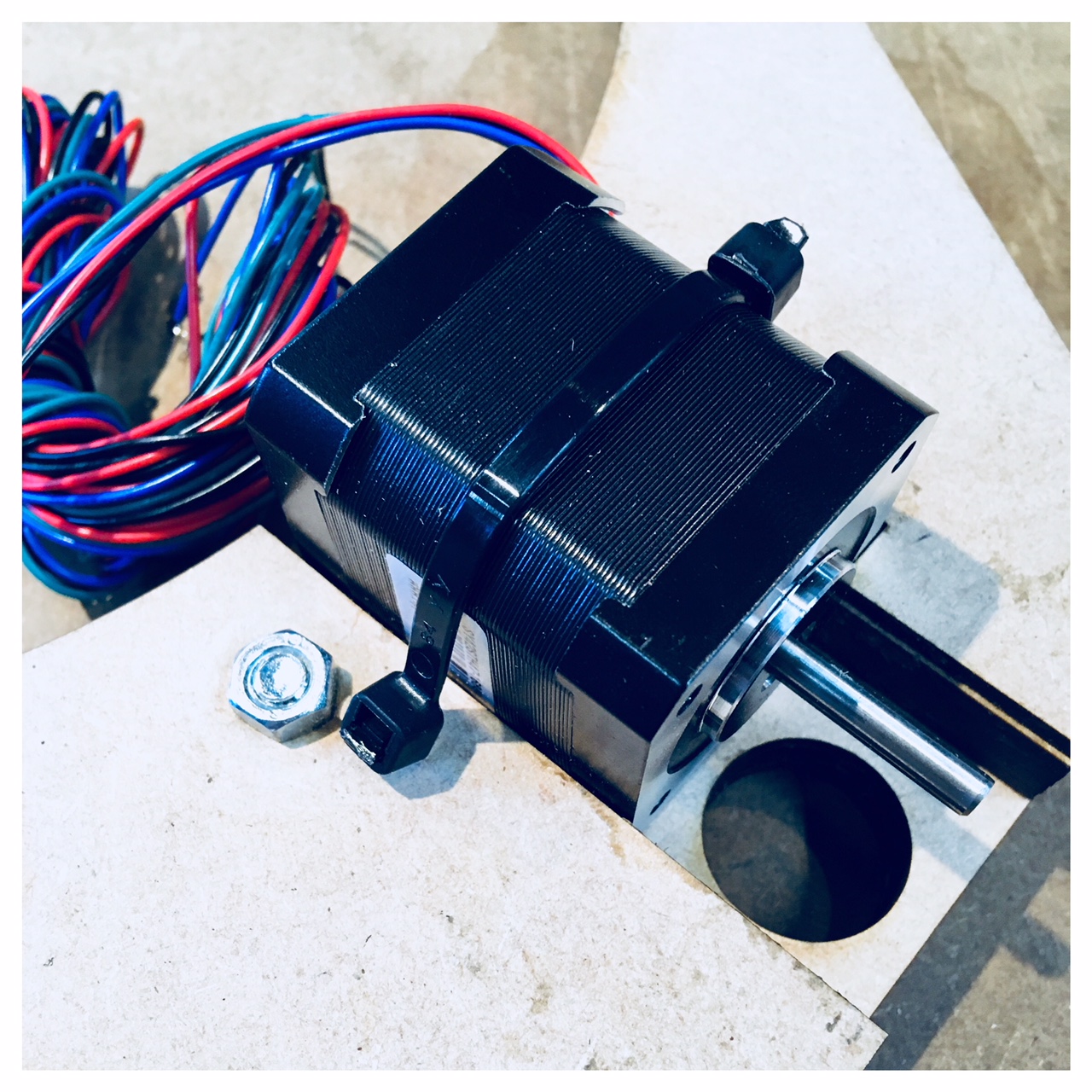
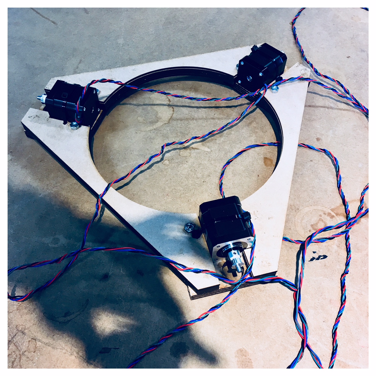
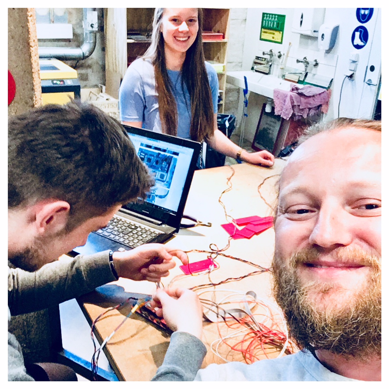
We all started this week with the same procedures as last week. We talked all together about the assignment and the course of the week and then split up into smaller teams with different tasks. As last week, I worked together with Anders Alnor. In addition, Carina was also with us this time. I started out adapting the top to the stepper motors and drilled holes to attach them. I have attached them with strips that are thoroughly tensioned similar to the clay printer made by Jonathan Keep. Link to Jonathan Keep's webpage
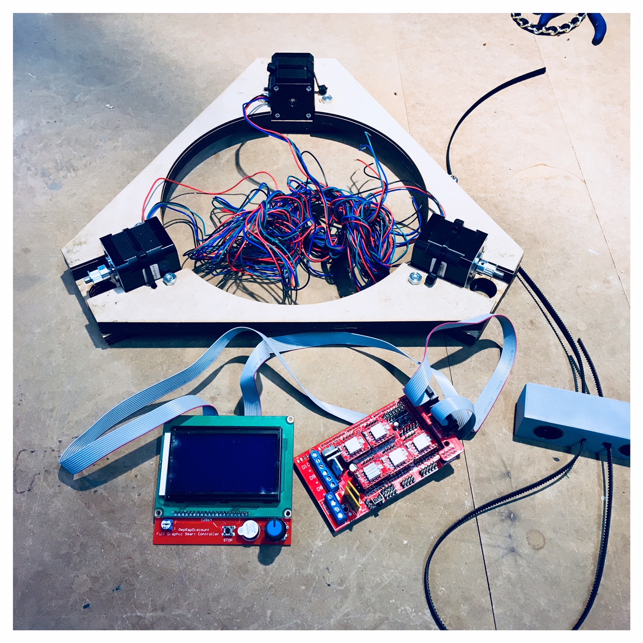
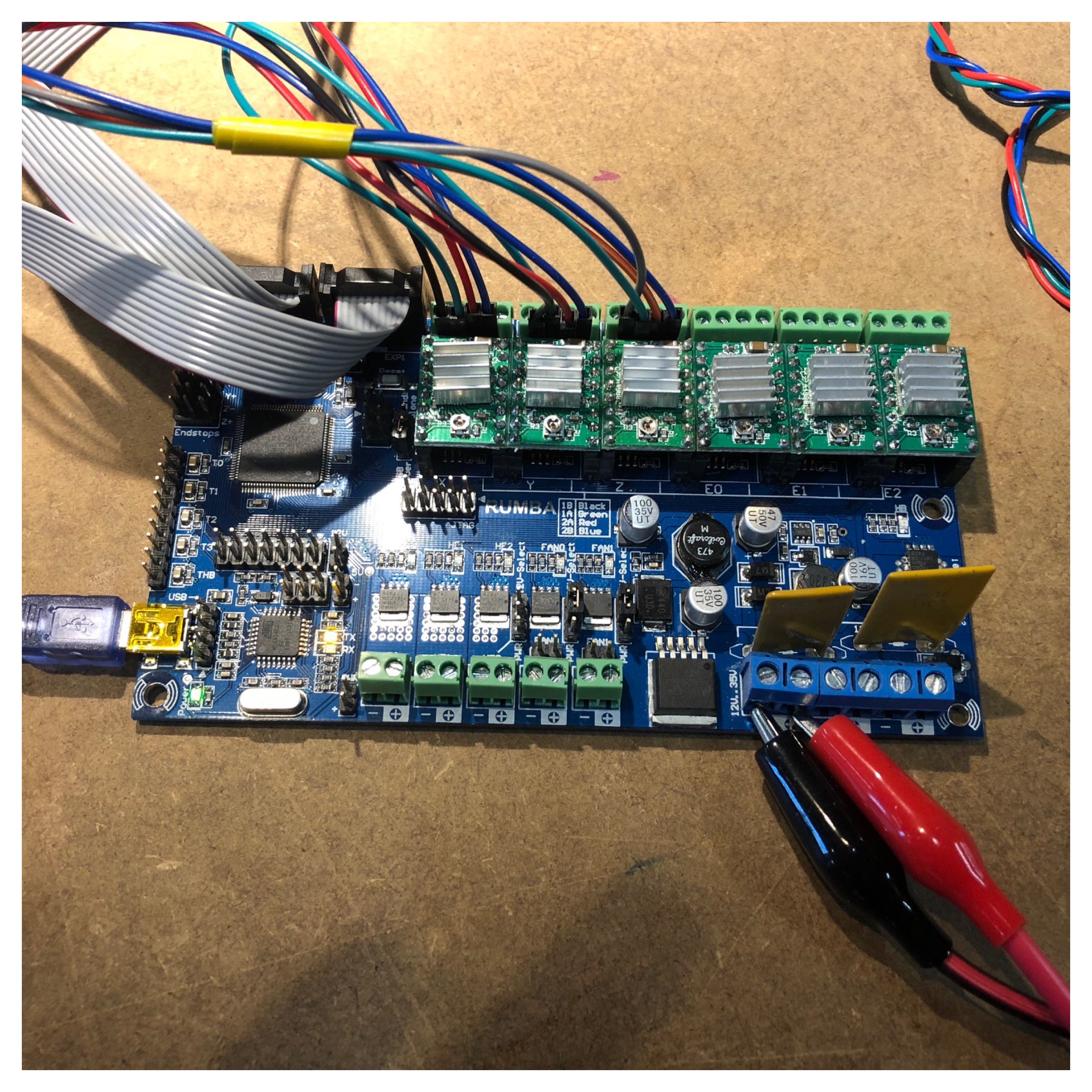
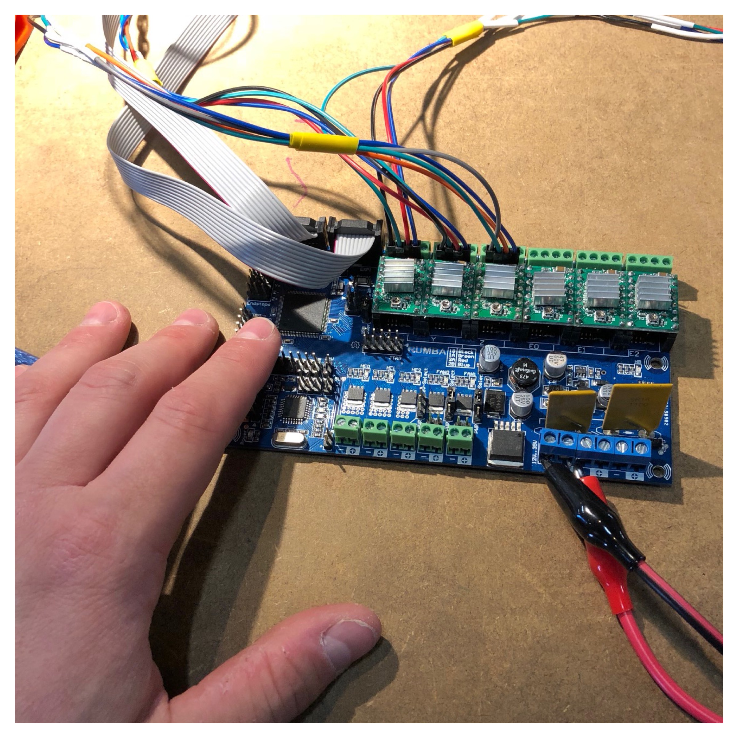
I then soldered all the machine parts together making sure that none of the solderings were exposed by using shrinkable plastic tube to insulate the wires. The first time the Arduino was put to the motor shield, an error occurred, which resulted in the shield burned off. We replaced this shield with a new board from RepRap called RUMBA (the blue board you can see on the pictures). It works with an ATmega2560. Six motor outputs powered by Pololu pin compatible stepper drivers.
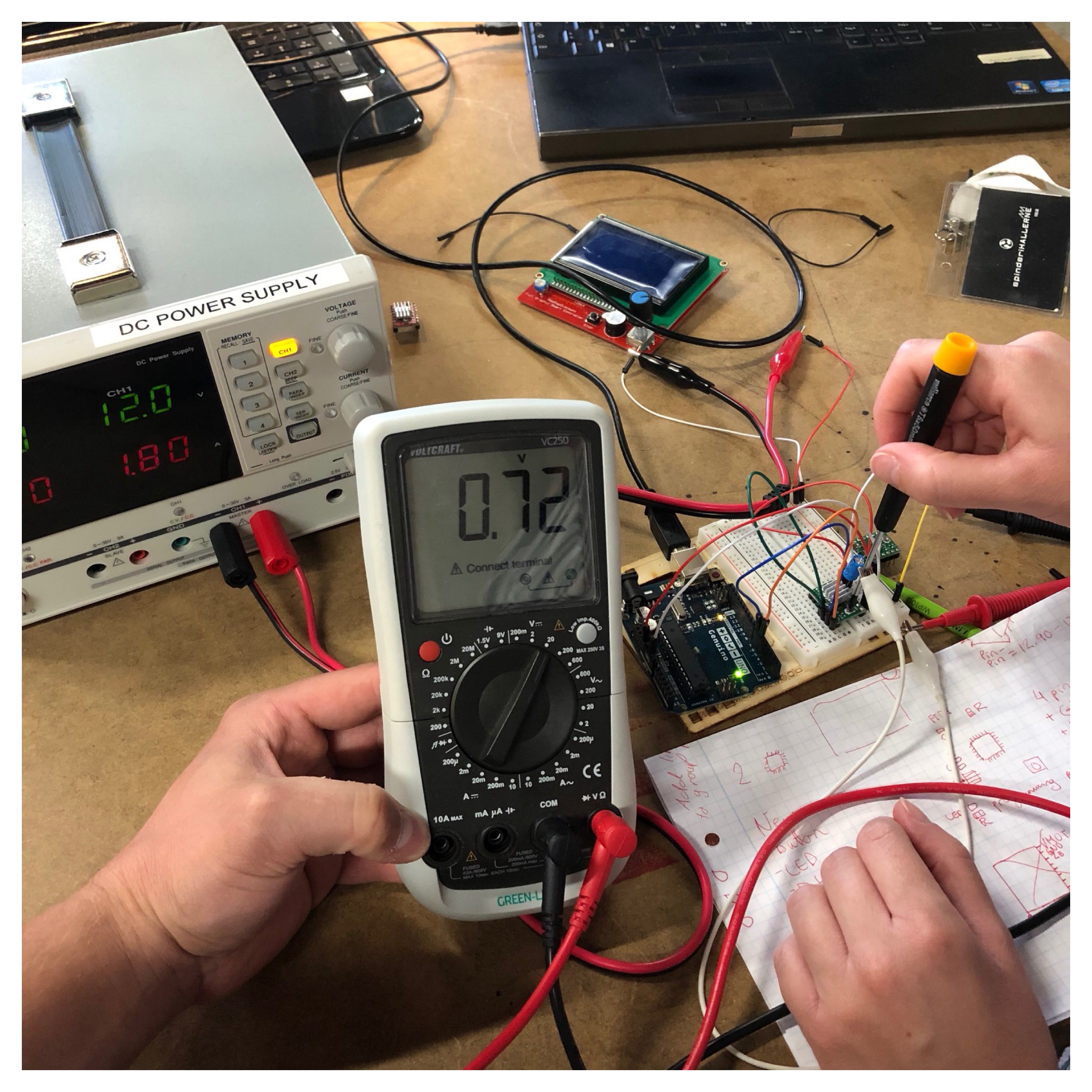
Here I mounted the pololus onto the RUMBA board (wich I helped Carina adjusting and adjusted one of the three pololus with a multimeter, a breadboard, Arduino, 100 uF capacitor, wires and a power supply. The power supply should be set on 12V and 1.8A for the green pololu. The multimeter should be set on 20V. GND should be connected directly to the board. But the VCC should be attatched to a screwdriver (check if curent is going through the screwdriver before you use it), then when you are turning the screw it is showing a number on the multimeter. You should keep turning clockwise until you hit 0.72 on the multimeter for the green pololu).
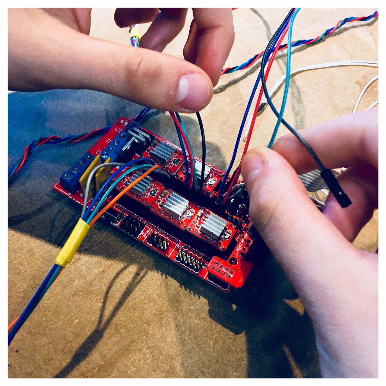
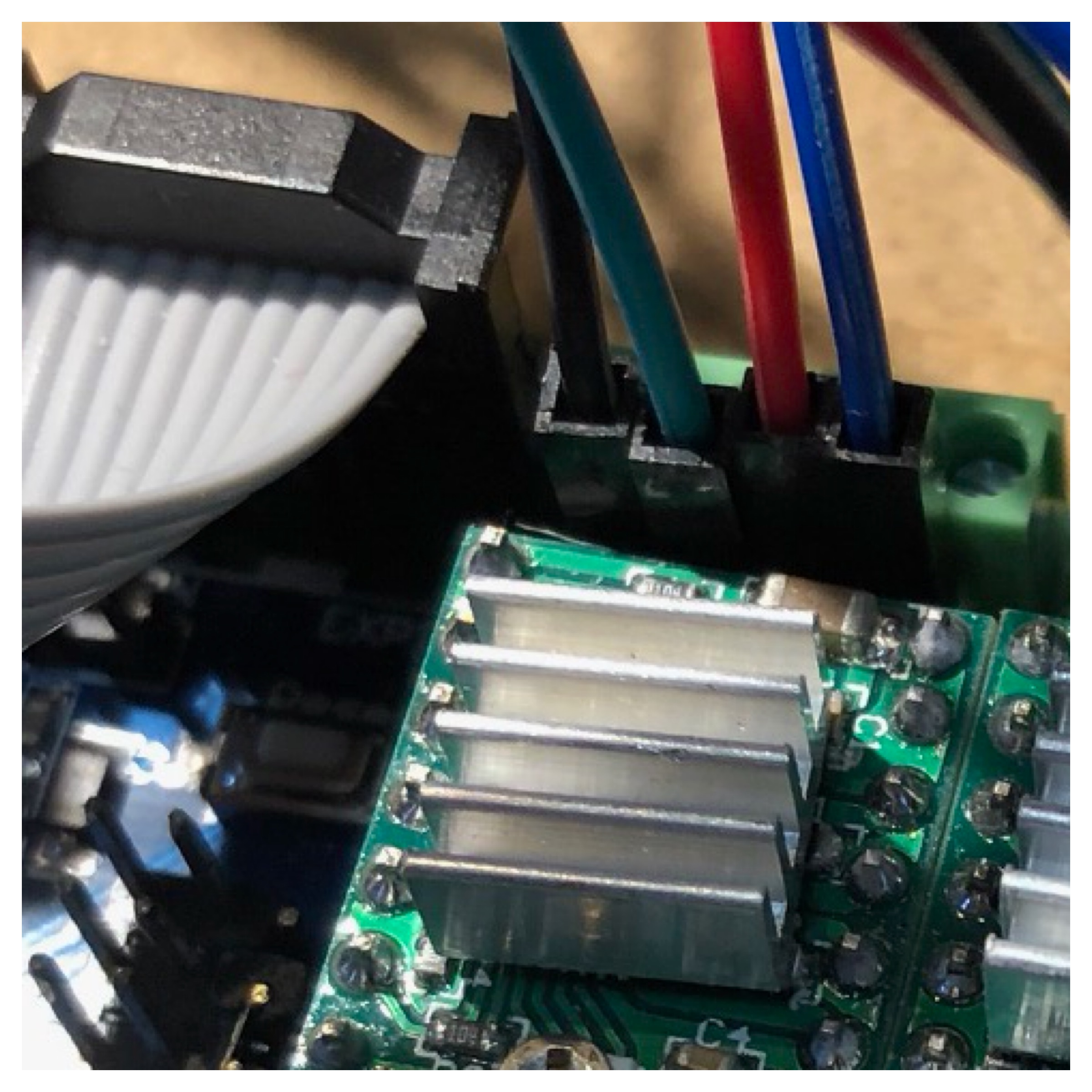
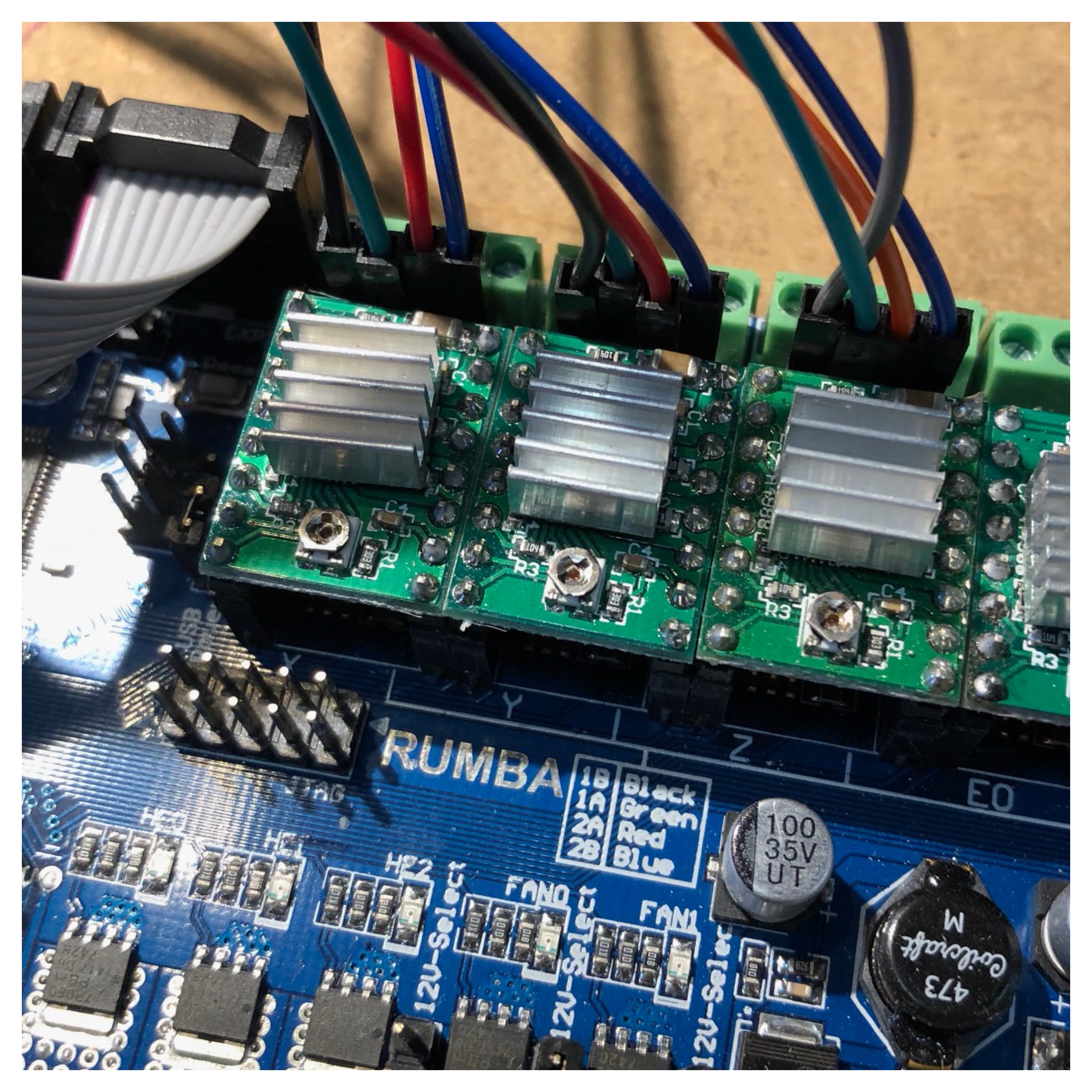
I then placed four wires for each of the three motors. An X, Y, Z which runs the three motors in each corner of the delta shaped printer. Here there is a black, green, red and blue wire comming out of the motor. It is extremely important that these wires are set correct. Otherwise the motors will run the wrong way creating a mess.
The RUMBA board are marked with the following text: 1B (The black wire), 1A (The green wire), 2A (the red wire) and 2B (the blue wire).
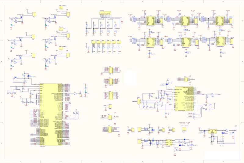
Under here you can see the Rumba schmatics or follow this link for further information about the RUMBA board. The blue board is an older model. Today the board is white: RepRap RUMBA
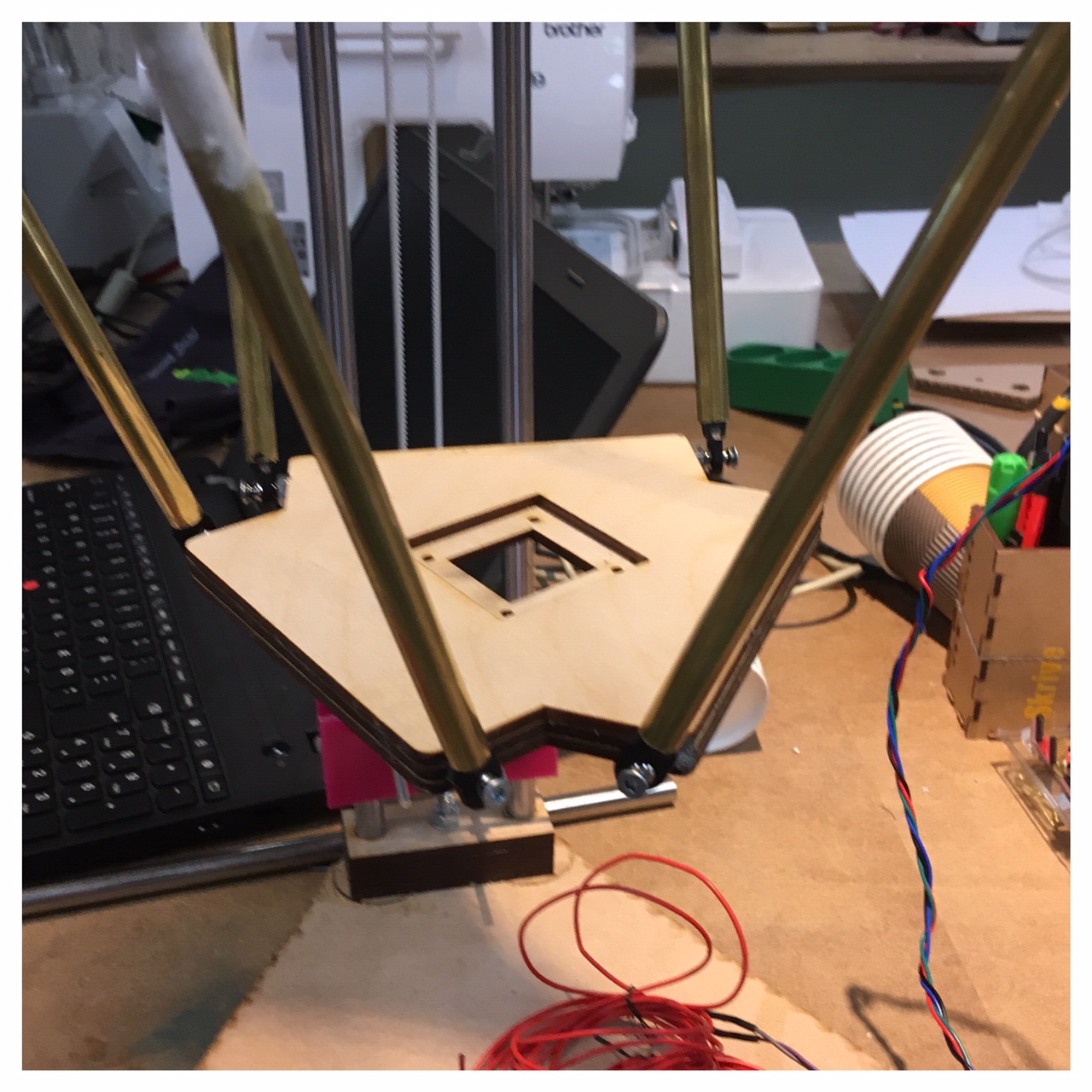
The extruder base
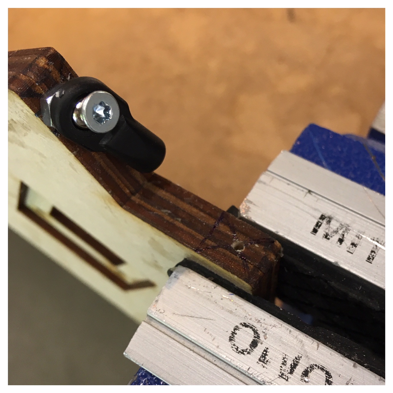
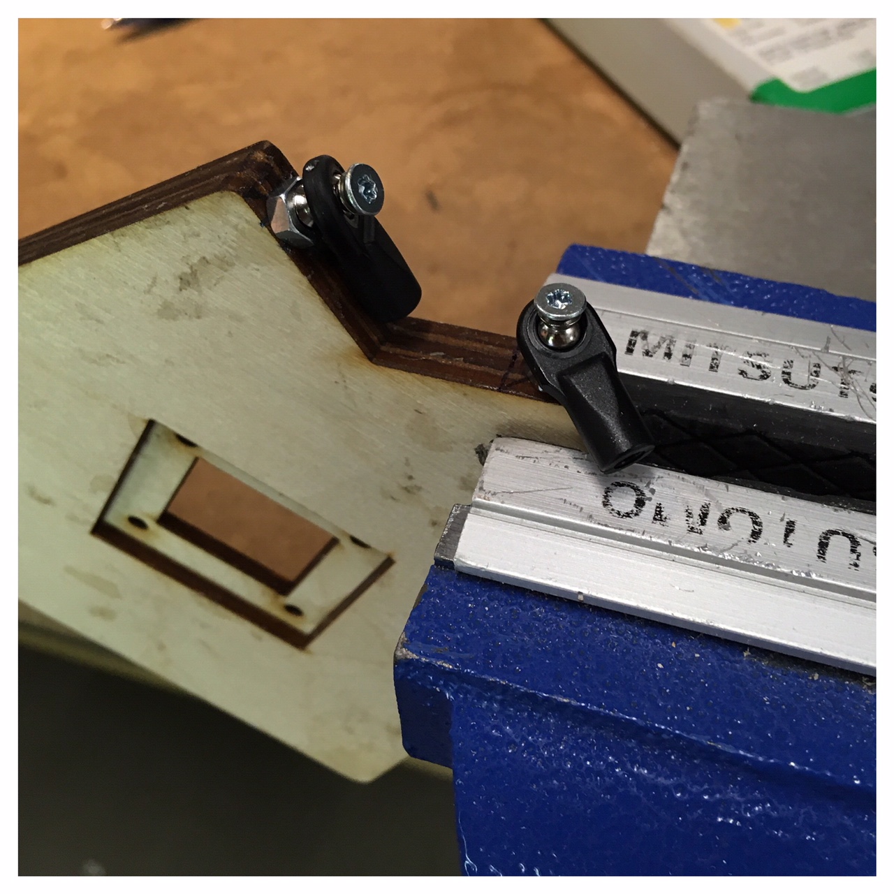
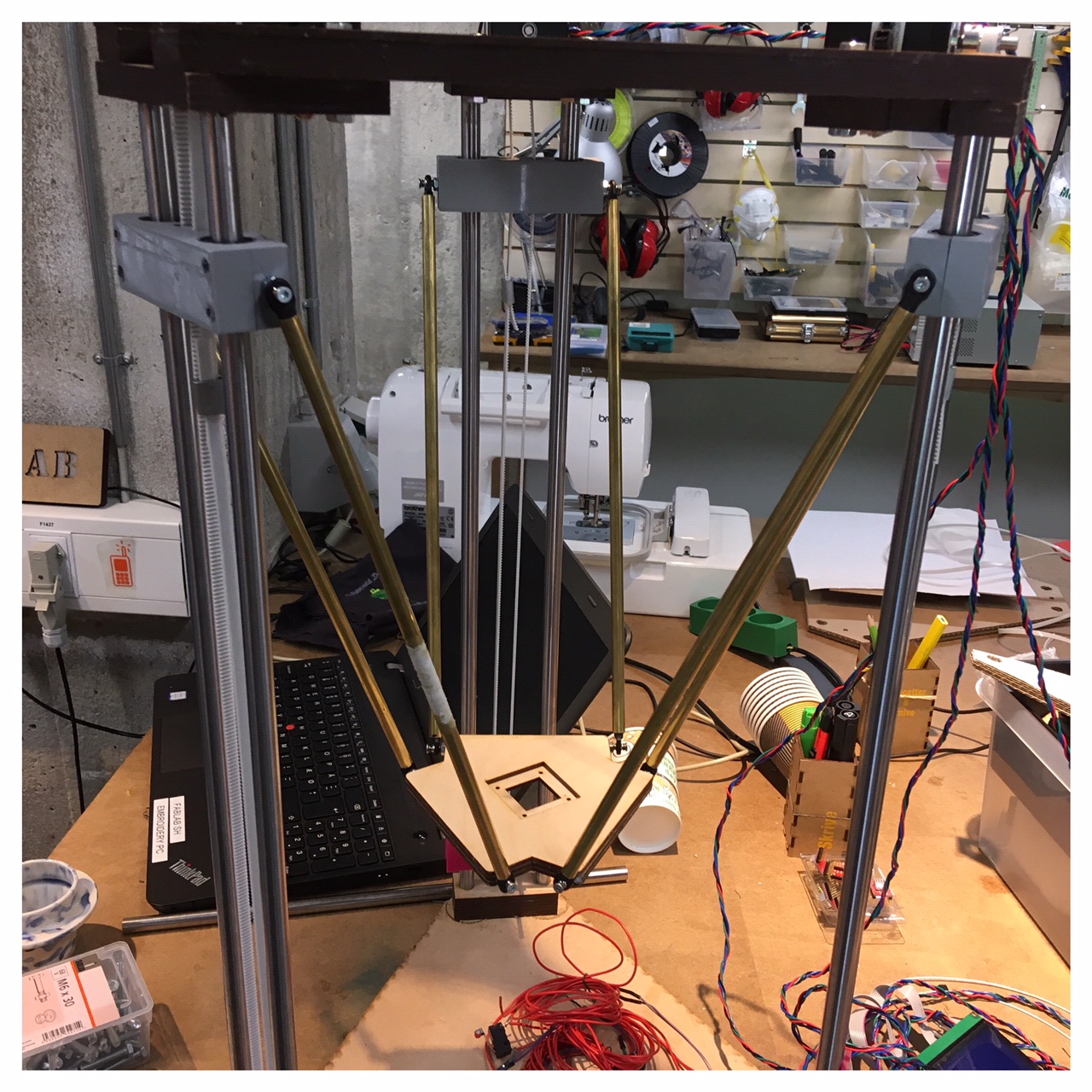
The next day, I assembled and mounted the brass rods that hold the extruder base and z-axis together. For this job, I used some small, thin screws that I have bought at the local hardware store. I drilled a small hole with a 1 mm drill before screwing in the screws so that the PLA wouldn't crack and same procedure with the plywood base (as we used for the extruder base).
Making The Machine Move with the g-code
I started out with assembling the maschine (the three steppermotors) with the board, making sure that the four cables from each motor was correctly assembled, otherwise the steppermotors will drive the wrong way as I pointed out earlier. The mortors and the cables each represents an axis, x, y and z, wich was marked with small letters on the board.
After a thorough talk about our group project I used two days with debugging the machine. I tested the board and the steppermotors. First making sure the motors could run, then getting the motors to go up with the g-code placed on a SD-card. I then printed the gcode from the SD-Card, but the files started with a auto zeroing, just moving a bit up, as you can see on the youtube video clip. This was still the first move of the delta printer and it assured me that the steppermotors run as they should.
Working as a group
It is hard planning to work as an efficient team. This week was kinda tough as coordination was the key to a succesfully group work. Since we as a group encountered several problems with making the g-code work. Communication was key in order to make sure everyone knew about the latest problems and had the latest version of the code in order to know what to do and start debugging. Who has done what, and what are the next steps. I think that large companies which have many and varied teams need to spend huge amounts of resources and time on management of the teams as well as communication to make things go perfectly.
Opportunities for improvements in the design
In many ways, this has been an important learning process for us as a group during the Fab Academy. A learning process that has also shown where improvements to the design can be done, if we/I once again want to build a delta shaped printer. Some of the improvements are to plan better. An example is buying the small components or order products we need. We have bought some things a little to cheap in for instace e-bay, and actually some of the pololus didn't work from the beginning, so we had to order new ones wich resulted in a lot of waiting time. For another time I think it's a good idea to buy a little more (to have extra) or maybe a little better quality to be more efficeint and also to get a better machine.
One thing that also could need an improvement is the frame that we made. The bottom and top is made of several 3mm MDF and glued them together. This is very hard to align the many pieces of MDF and makes the whole structure very unstable and quite inaccurate. It also makes the bearings to run badly, if theres just the smalest incorrectness between the two steel bearings, they drive way too tight and not smooth at all.
A great opportunity would have been to mill the base and top in one piece on the Shop Bot CNC. But unfortunately we had an accident with our CNC machine, so it was not working at the time and that is one of the reasons why we laser cut the MDF.