This week we have learned about input devices, which means to use various sensors to detect and send the data, in a form of variation of the voltage, to the microcontroler, process the raw data, and then send them out through the serial port.
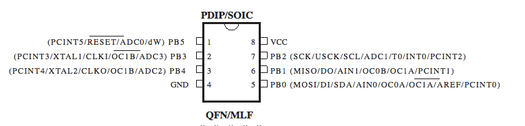
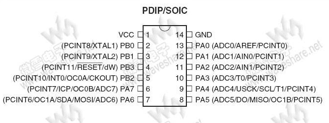
In the preparation, we have to read the datasheet of the microcontrollers and get to know the functions of each pin. Some pins can read analog signals, while some pins can only read digital signals.
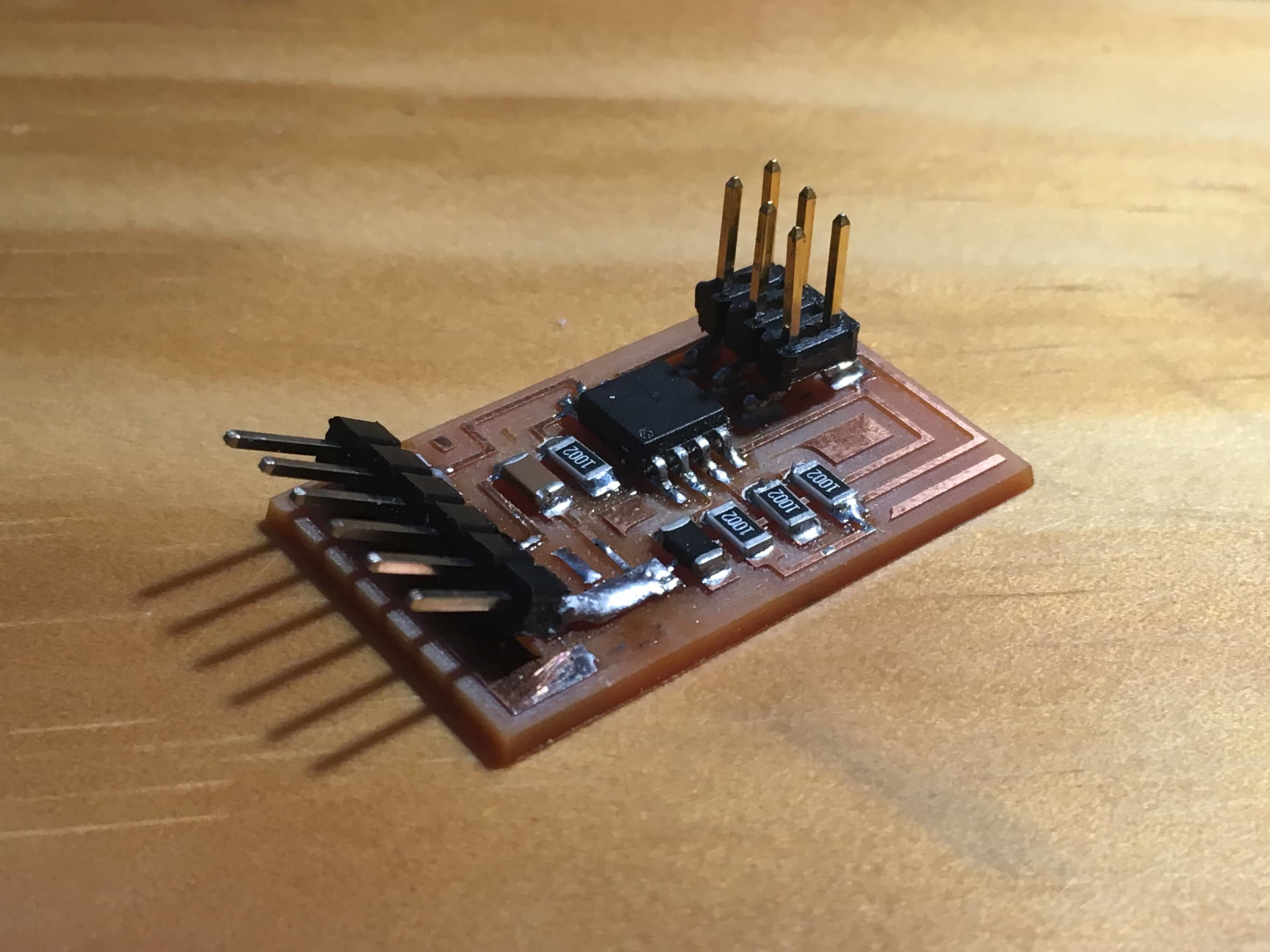
Making the board
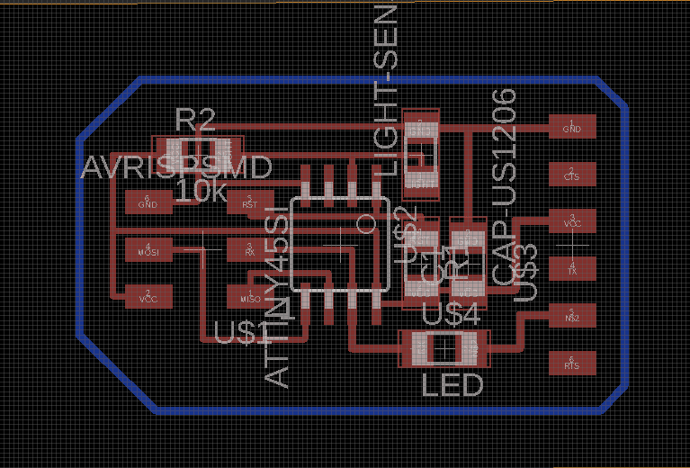
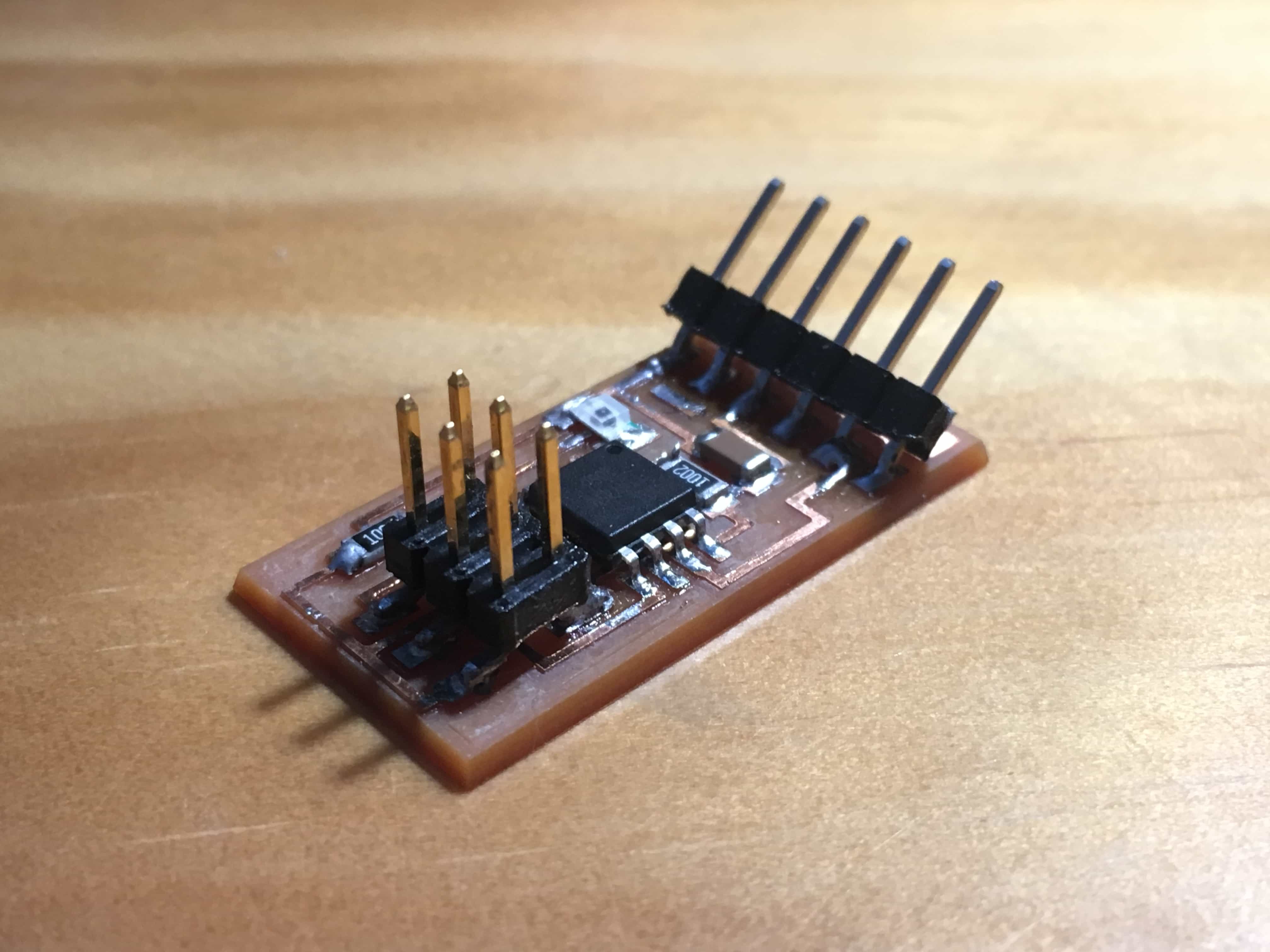
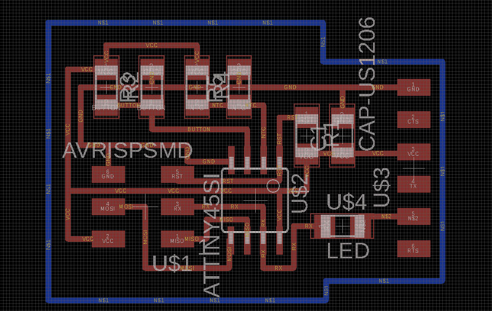
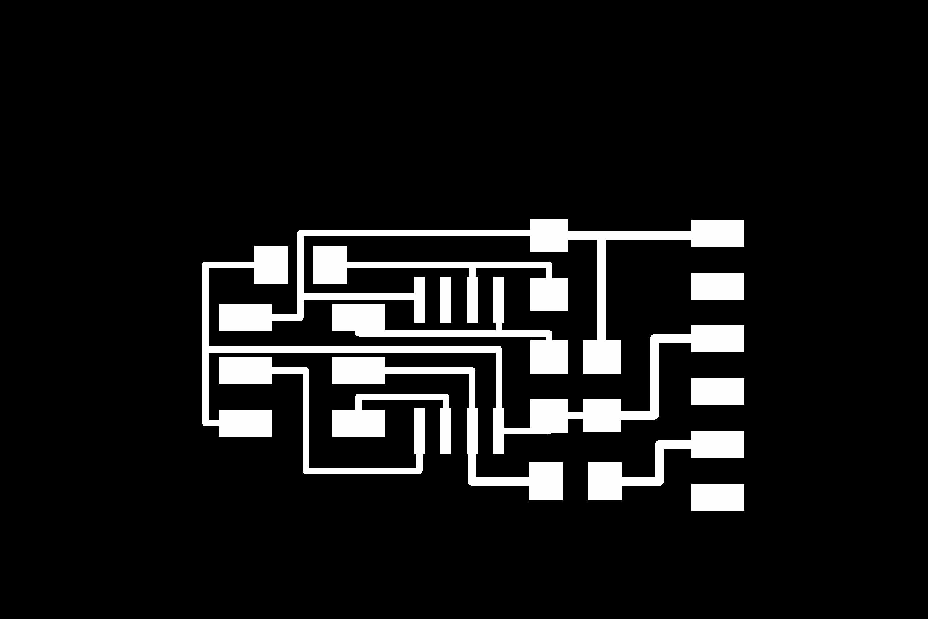
We have to design the board first. I wanted to use the light sensor and temperature sensor (NTC), so I viewed Neil's Design and replicate the skematic of the circuit with EAGLE. After that, I route the board and milled it.
Another important thing is to read the datasheet. On my board I chose PB3 as the analog in pin to read the data. From the data sheet we can know that PB3 pin can read analog signal and it can be used as input pin. In fact, it could also be used as an output pin.
DESIGN FILES :
Light.sch Light.brd NTC.sch NTC.brd
PNG FILES:
light-traces light-interior NTC-traces NTC-interior
Light sensor board
NTC board
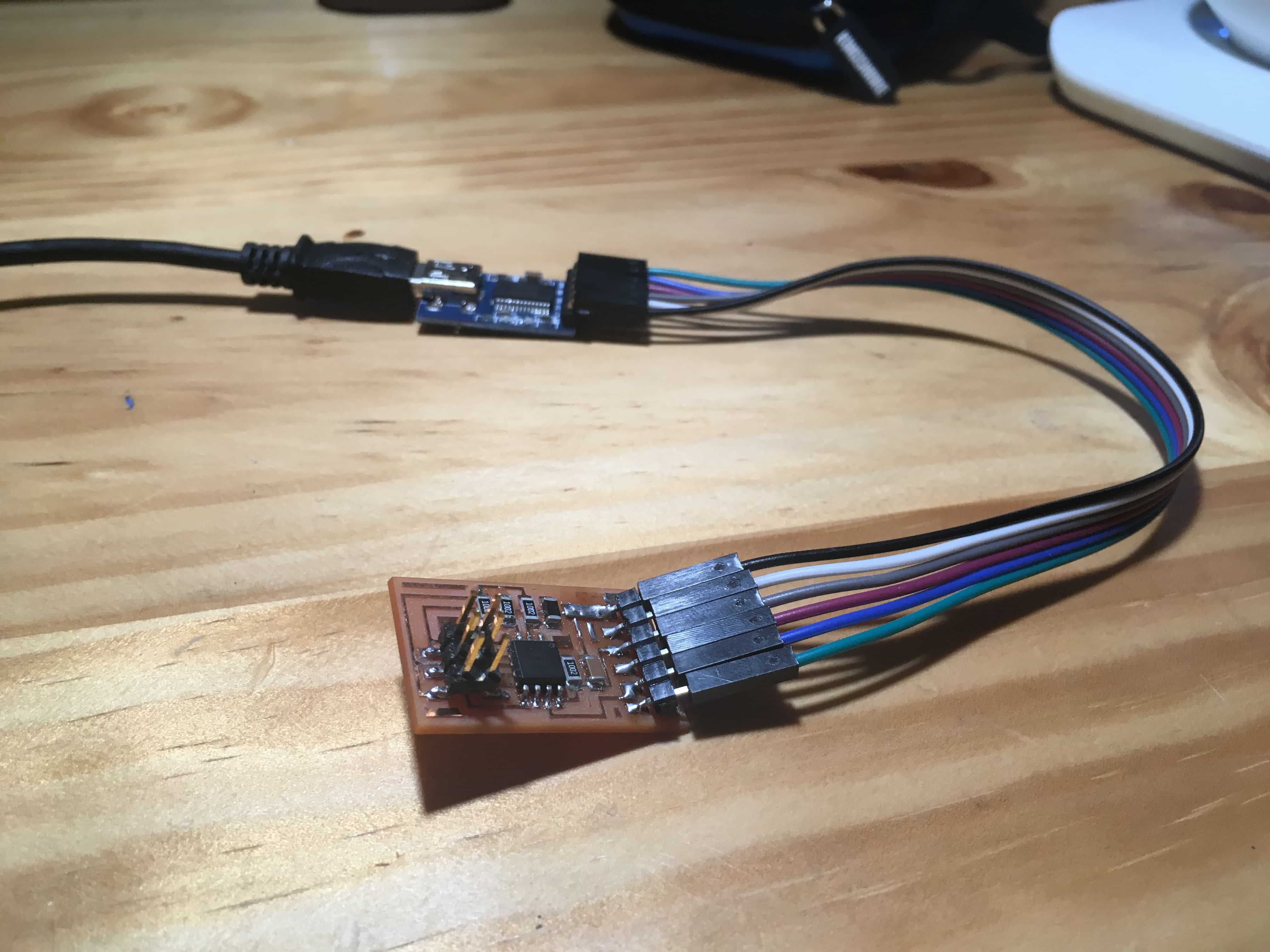
Preparing FTDI Serial
We know that we should install a driver for FTDI serial port. So now we have to download it from the FTDI official website and install it with the instruction on the site. After that, we can test our serial port.
One important thing: I failed several times reading the data because I did not get the correct connection between my board and my FTDI board. Remember, Tx means to send the data out while Rx means to recieve data from other devices. Therefore, we have to connect Tx Pin on the board to the Rx pin on the FTDI board.
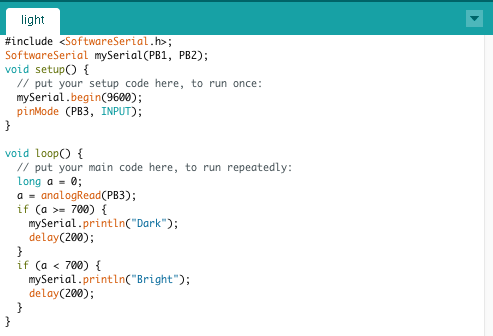
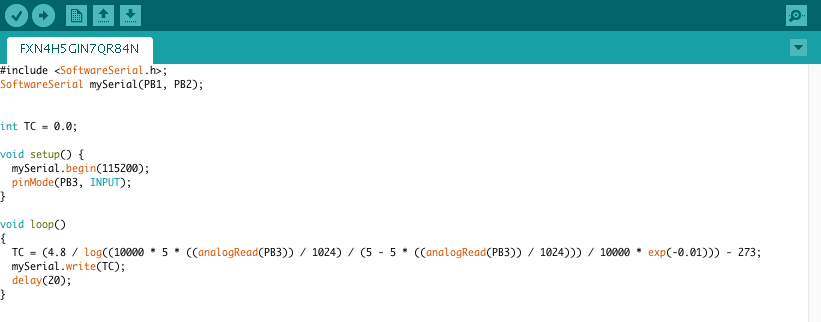
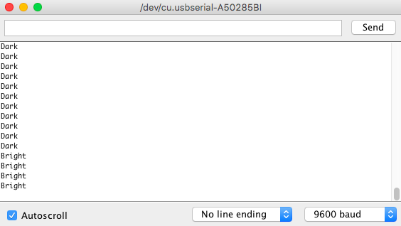
Read the data
Now let's code on Arduino IDE and see the data from our board. Make sure that you have included <SoftwareSerial.h> and the Rx / Tx Pins.
Problems
1. At first I did not found out my mistakes in connection of Tx and Rx, which resulted in that I could not recieve any data.
2. In the making of the board, I heated the board too much so that one trace on my NTC board was split from the board. I had to use a metal piece to solder the missing trace. This taught me that I should make things done fast and accurate.
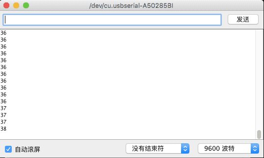
3. Interestingly, when I used my hello 44 board to connect a outside light resistor module and tried to read the analog signal, it turned out to be only two values: 23 and 1023. I suddenly Realized that the pin I connected does not have a function of analog reading, or the module itself was programed to send only two values. So I get back to read the datasheet of both the microcontroller and the sensor module.
