
WEEKLY ASSIGNMENTS
Machine Design
The whole thing starts right after the official opening of our lab, so the time, in general, wasn't on our side. we have 2 ideas in our mind
1- CNC
2- Hot wire foam cutter
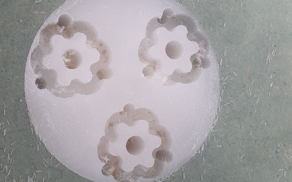
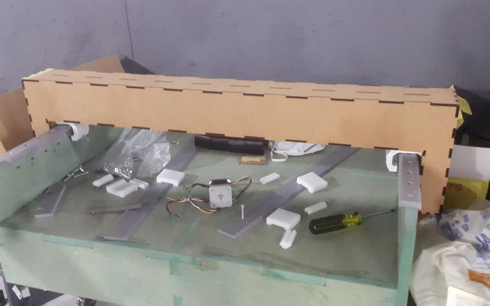
CNC was the one we start with, most of the parts we used in this machine were build from the material we have in our lab and using the 3D printer to print the parts we need like the z-Axis holder and the drimel munting.
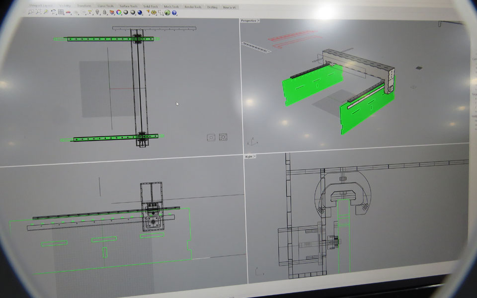
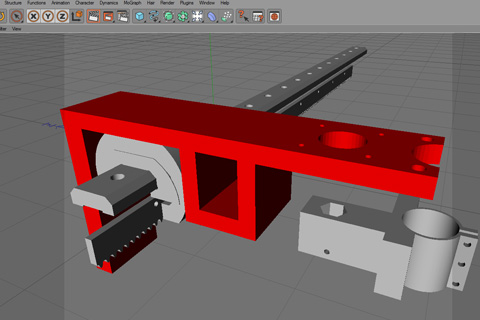
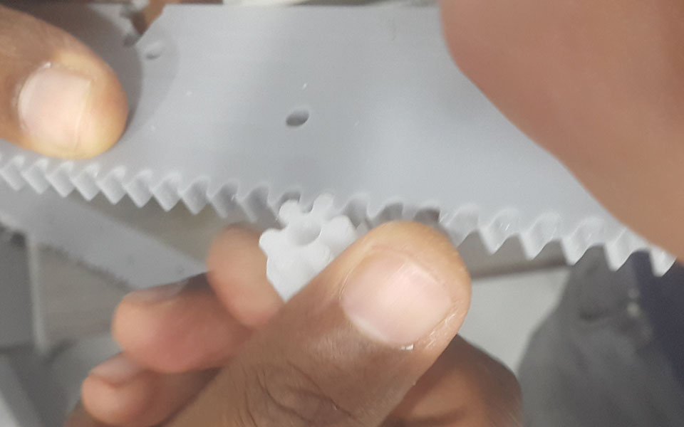
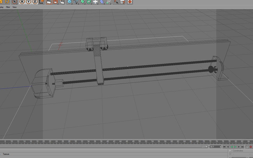
We used Dayvik rhino machine file, and modify it to the design size we agree to work on the pinion, sliding linear guide, tension box. all design and build inside the lab
for the movements, we used 4 Nema 17 stepper 2 motors for x-axis and y-axis movements and one for the z-axis
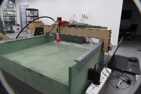
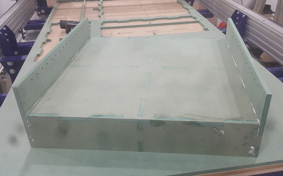
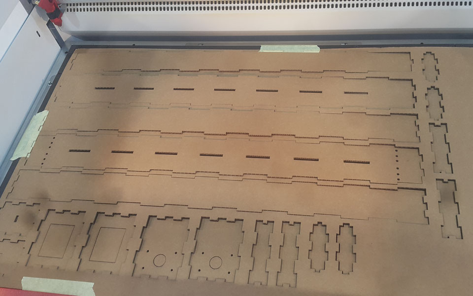
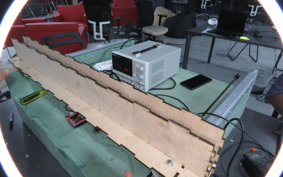
Using shopbot to build a tied box (material used for it was HDF15mm ), on the two wall sides on the top the thickness is 14mm so the two acrylic rails track will be fitted, and it will be drilled to be mounted to the wall of the CNC.
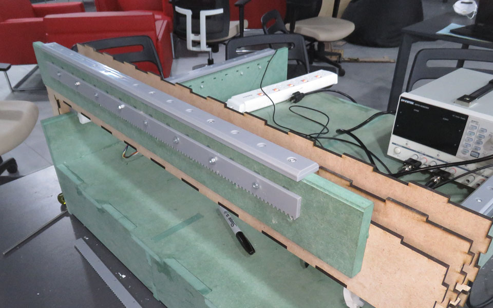
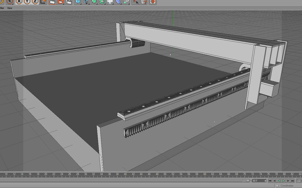
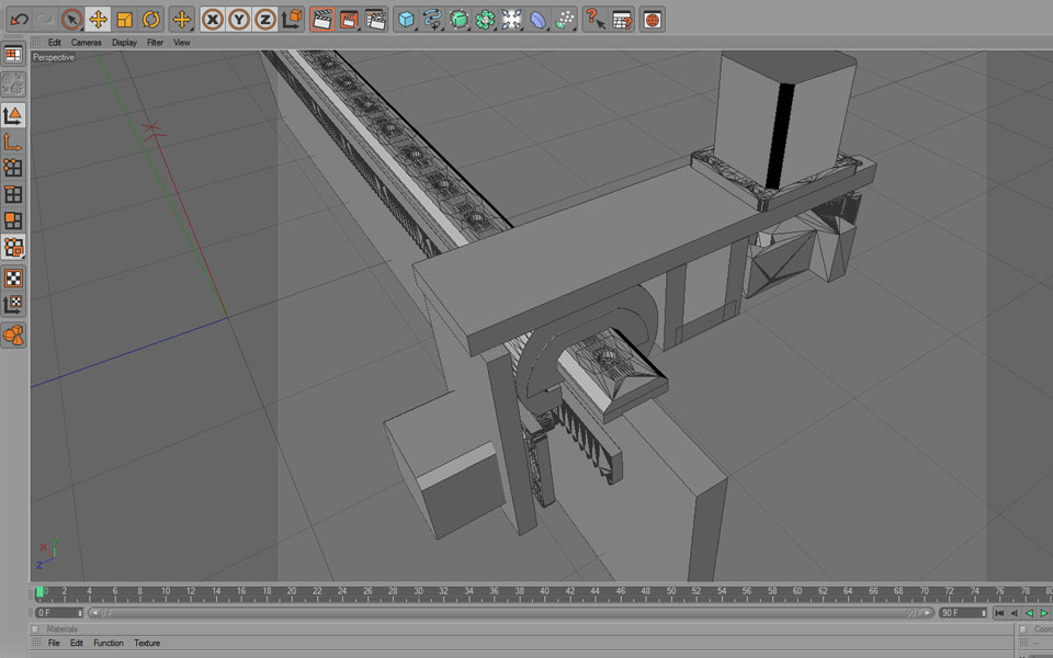
Testing the main bridge that will care out the Y and the Z axes. The first couple of tests I face some issues regarding dimensions and scaling I used Cinema 4d to design the bridge then export the file as DXF, then when I try to cut it on the laser it scales down, even trying to export it as an illustrator it shows the same issue. Then I try to design the whole thing using illustrator again the same thing it scales down, during this troubleshooting we used Rhino it was fine. The full bridge is very strong and can handle weight and twist.
After that I was still looking why this scale down happened, as a logic it should work, then I found out that when I worked on the file (AI ) in mm and open it on Inkscape the scale is not 1:1 it was
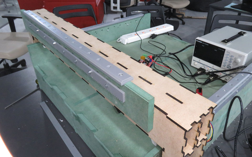
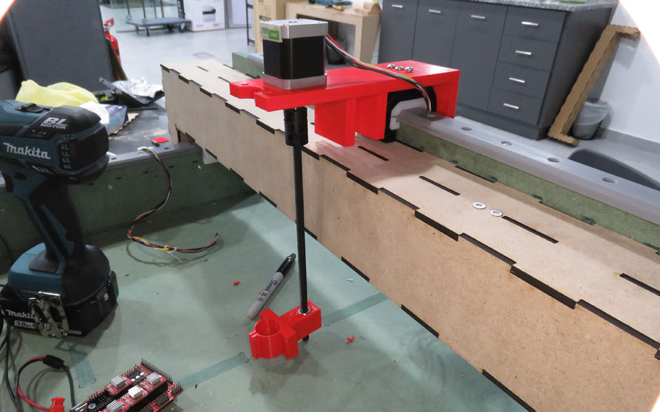
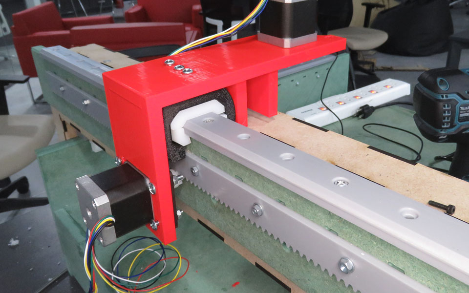
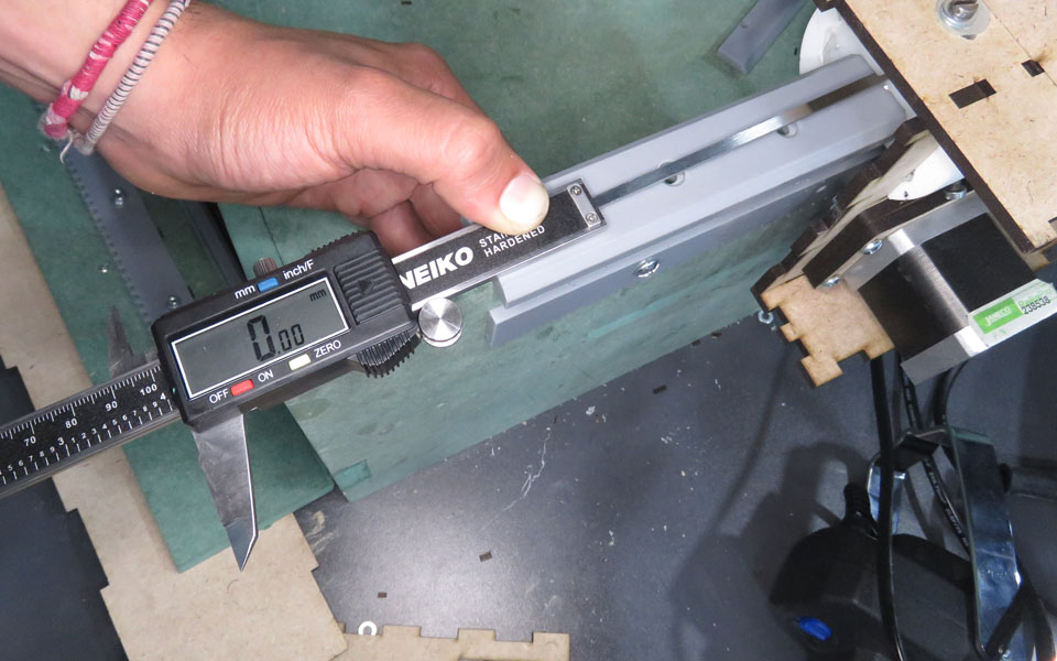
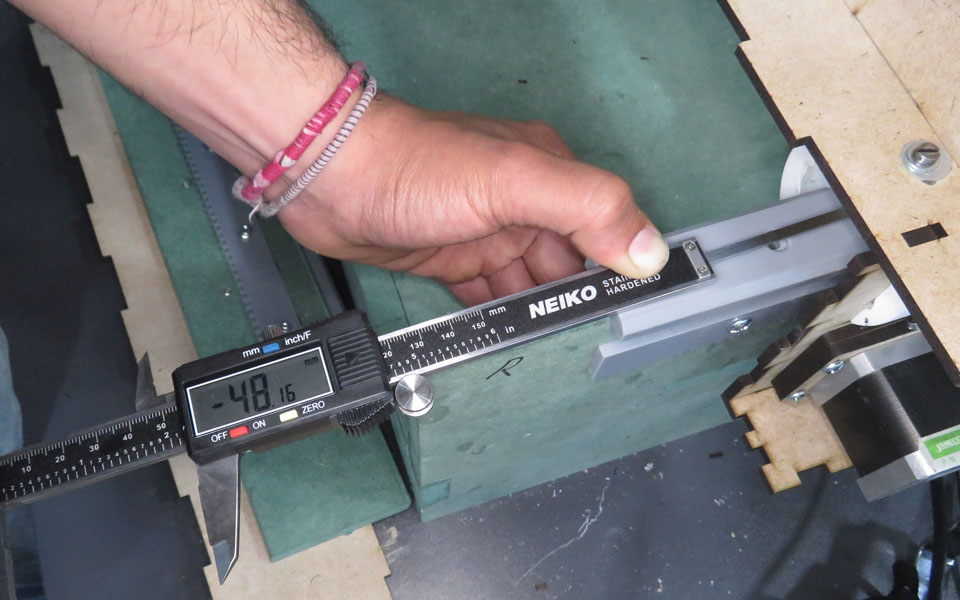
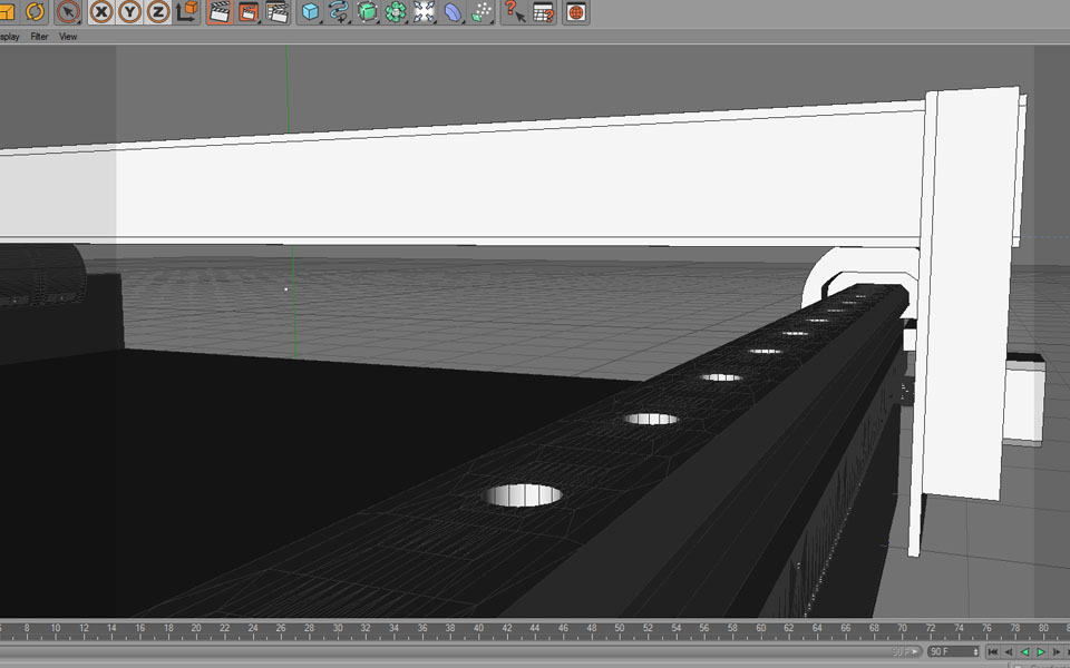
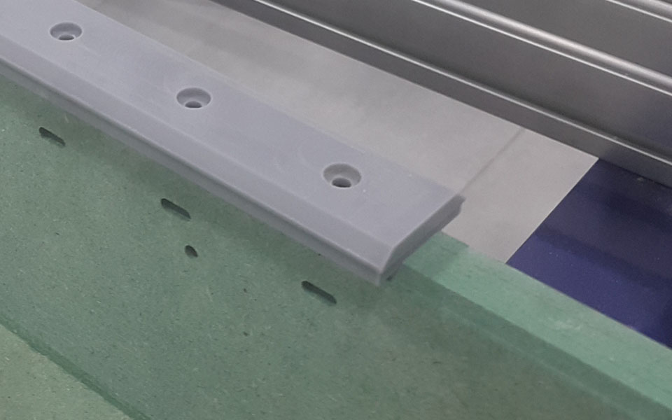
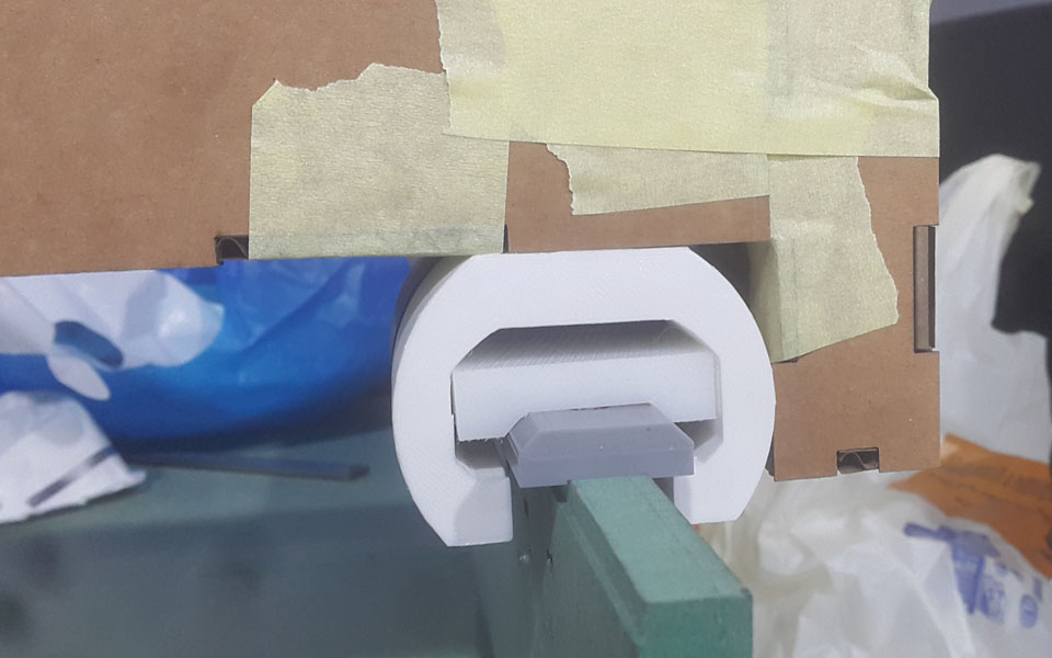
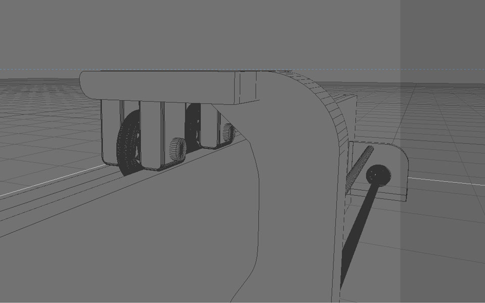
The creative upgrade for the machine will be using bearing system rail tracks on the two sides for the X-axis each one will have two bearings linked to a lines guide on the side as shown on the images mounted to a step motor, that will make it move more smooth with less traction between the surfaces, and it doesn't need that much load. The same bridge for the Y axes but without the two sides that care the step motors, on that bridge, it will use the Bearing system as the one for the X-Axis. With the same movement setup for the Z -axis.
http://fab.academany.org/2018/labs/fablabtechworks/w10/index.html