
WEEKLY ASSIGNMENTS
Input divice
For this task, I decided to do 2weeks tasks, and at the same time to work on one of the parts for my final project.
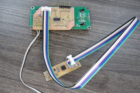
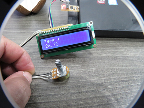
I will build a board ( temp sensor and LCD ) to read the temperature from the meeting box ( for my final project ) and display the reading on the LCD.
using Eagle to design the schematic- Board, One the things I face it how to link the LCD to the ATTiny 44 and the Resistance, so I look at other cases, and exercises, plus reading the data sheet for the NTC sensor. and understand how the NTC sensor read the data. that was another learning care for something and not familiar with and don't have high experience with it, the only experience I am getting in electronics is from fabcadamy
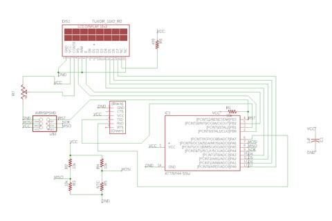
designing the board I face an issue that some connections are not linked it only show a hairline, it took me sometimes to get to the best linked with only 2 unconnected places, I asked our instructor, how to fix this and he told me that I can do a bridge to connect them ( i am using one layer ).
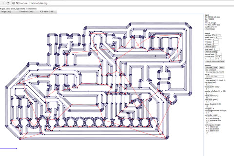
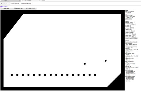
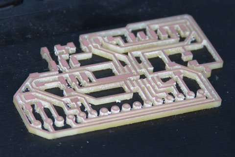
When I start with the milling for the board I found out that still, I am facing the same problem I face in week (Electronics Design) task, that the Bit did not mill all the surface. It mills 50% from the full board, and when I increase the milling depth, the result was as below. I was planning to use the board as is, But I desid to complete this later as an experiment for me.
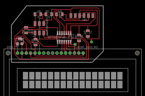
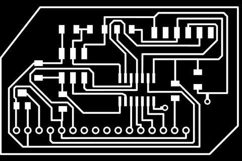
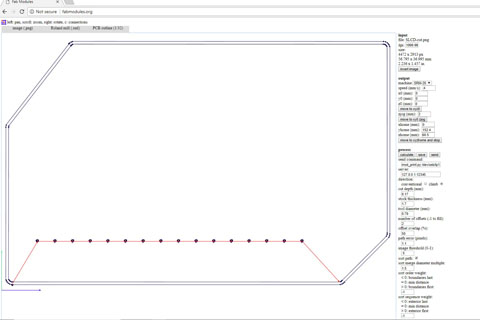
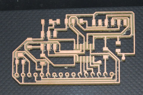
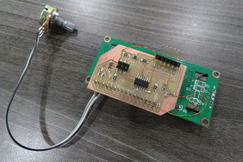
With the new bit the milling was nice, then I found out another issue that 2 lines going out of the attiny are attached, so the quick fix was to cut one of the connections and do a wire bridging. A problem solved.
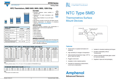
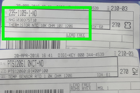
NTC- is based on the variation of resistivity semiconductor with temperature. The term comes from thermistor temperature sensitive resistor.
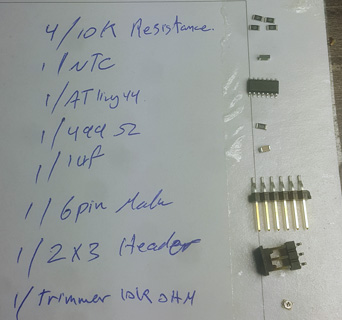
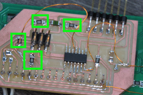
All the components I need for the Board.
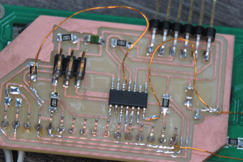
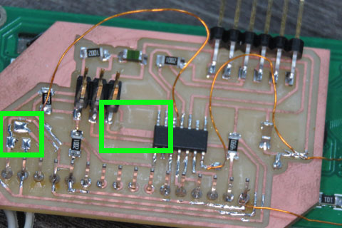
The two lines are merged, I cut the line going to the LCD connection and solider a bridge wire.
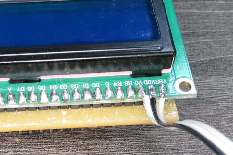
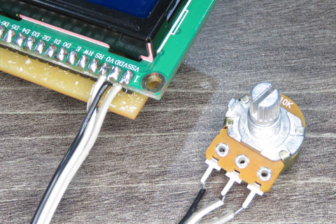
the Trimmer wasn't that easy to solider, after finishing the board and mount LCD to it.
// include the library code:
#include <LiquidCrystal.h>
// initialize the library by associating any needed LCD interface pin
// with the arduino pin number it is connected to
const int rs = 10, en = 8, d4 = 3, d5 = 2, d6 = 1, d7 = 0;
LiquidCrystal lcd(rs, en, d4, d5, d6, d7);
#define B 3750.0
#define R25 10000.0
float T;
float R, A;
void setup() {
// set up the LCD's number of columns and rows:
lcd.begin(16, 2);
// Print a message to the LCD.
lcd.print("Temp :");
}
void loop() {
// set the cursor to column 0, line 1
// (note: line 1 is the second row, since counting begins with 0):
lcd.setCursor(0, 1);
A=analogRead(6);
A = 5*A/1024;
R = (A*10000.0)/(5.0-A);
T = 1.0/(log(R/R25)/B+(1/(25.0+273.15)))-273.15;
lcd.print(T);
}
To download the files, right click with the mouse and chose “save link as”