
WEEKLY ASSIGNMENTS
Embedded Programming
Stepping out of my comfort zone again in the direction of programming. but this time after we get a long lecture from our instructor Sibu, explaining ( 0,1) machine language and how it works plus the logic behind this.
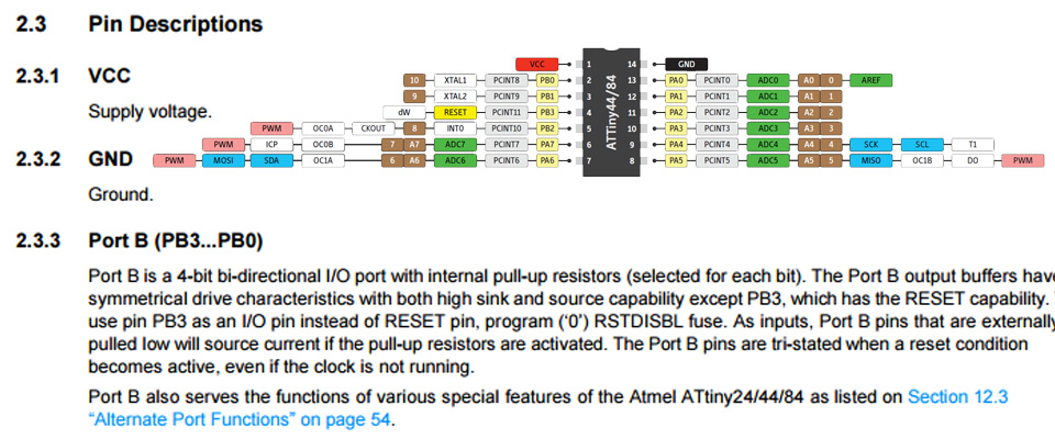
The datasheet is the manual of any electronic components They explain exactly. How to use and what are they for. It delivers you an idea especially for someone like he this is for him and experiences it shows or informs are the pins configurations like important features (memory, number of pins, power, and ground). From the datasheet and the diagram for ATtiny 24/44/84, there are two sections on the chip as PA and PB, VCC, GND RESET
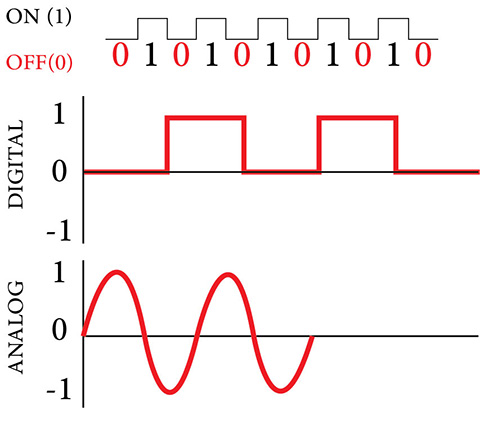
Binary is a numeric system that only uses two digits ( 0,1) Our PC's operates in binary, that meaning all the data will be converted into the computer as zeros and ones.
The 2 digits (0, 1) in this system are representing 2 values (True (1) or False (0)). Multiple digits can be used to store large numbers and perform complex functions.
1- One bit contains a single binary value — either a 0 or a 1.
2- A byte contains eight bits, which means it can have 256 (28) different values.
These values may be used to represent different characters in a text document, the color RGB values of a pixel within an image file, or many other types of data. The number of binary digits small or big as a file or an application where can be read by a computer processor.
All the binary data that compiled in a program called Machine Code that will be executed in CPU

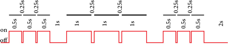
The concept I will work on to my make the light blink as ( SOS), from what I read on the net about programming, you need as the first step to identify what your program should do (function), when I push the button the light will send SOS light message as long as I hold the button down. so I found the code for SOS ( --- __ __ __ --- ), I will make each dash blink for 1/2 a second, and the space between each dash 1/4 second with a 1 second off between small dashes and big dashes ( waiting time ) when the SOS light end to loop it, there is a waiting for 2 seconds before it starts sending the SOS light message
The loop function is repeated continuously because it is called by a hidden loop that controls the execution of the Arduino program. In other words, the loop function is the body of a loop that is running in a master (or main) program.
Write a HIGH or a LOW value to a digital pin.
digitalWrite(-----, HIGH) // sets the digital pin ... on //
digitalWrite(-----, LOW) // sets the digital pin ... off //
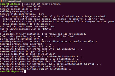
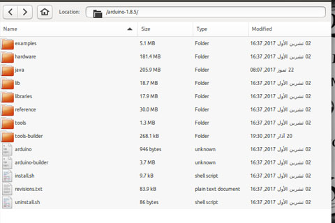
Install Arduino
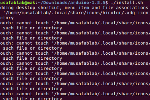
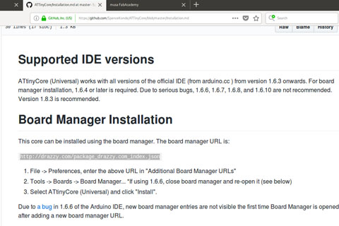
first remove the old version from my computer and istall the new one and add the libriry to it
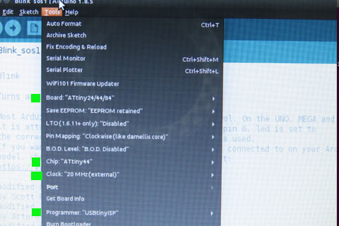
In the tools i verify the setup for Attiny44
Here are some of the web pages i sed to learn more (Void Loop , Void setup, delay ... ).
https://learn.adafruit.com/adafruit-arduino-lesson-2-leds/blinking-the-led
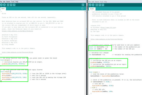
using the programs ( Examples ) blink
// the setup function runs once when you press reset or power the board
void setup() {
// initialize digital pin LED_BUILTIN as an output.
pinMode(LED_BUILTIN, OUTPUT);
}
// the loop function runs over and over again forever
void loop() {
digitalWrite(LED_BUILTIN, HIGH); // turn the LED on (HIGH is the voltage level)
delay(1000); // wait for a second
digitalWrite(LED_BUILTIN, LOW); // turn the LED off by making the voltage LOW
delay(1000); // wait for a second
}
I change the LED _BULITN to led , change the digitalWrite to 125 milliseconds as high and 65 milliseconds as low. it took some time to test it,the final milliseconds test that work ok with me in the download file in this page, and the problem was from the start I used too many commands and that makes it hard for me to test it and see where I am heading with this program as a beginner, the Setup for the light as (SOS) wasn't the best thing to start testing as a beginner.
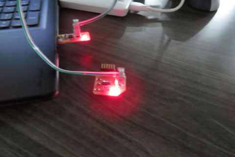
The first round was fine when Ii linked it to computer the light was on and off, this is was the first step to make sure this programe is running ok, but when i add the Click Button to the program, there was other issues i need to deal with. first i start understand the If and ealse meaning in programing, and how they work inside the program work flow.
Description
The if…else allows greater control over the flow of code than the basic if statement, by allowing multiple tests to be grouped together. An else clause (if at all exists) will be executed if the condition in the if statement results in false. The else can proceed another if test, so that multiple, mutually exclusive tests can be run at the same time.
Each test will proceed to the next one until a true test is encountered. When a true test is found, its associated block of code is run, and the program then skips to the line following the entire if/else construction. If no test proves to be true, the default else block is executed, if one is present, and sets the default behavior.
Note that an else if block may be used with or without a terminating else block and vice versa. An unlimited number of such else if branches are allowed
https://www.arduino.cc/reference/en/language/structure/control-structure/else/
( https://www.arduino.cc/reference/en/language/structure/control-structure/else/)
When i try to run the program, the button did not work as it should be. getting back to board design ( SCH - BRD ) from the last assignment. the button pin number was wrong it was 2 in the program, and it should me 3. fixing this issue and testing the program the button on the board worked fine, and start sending the light signal.
To download the files, right click with the mouse and chose “save link as”