Week 20
My Envisaged Final Project
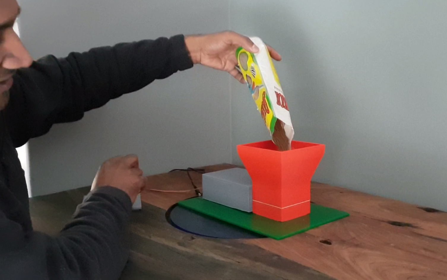
Trying to think of what I would like to make as a final project. I looked what problem do I have that I could use this opporunity to solve my problem. Last year I build a Fish tank , which came out very beautiful . The problem I had was that I would sometimes forget to feed the fish, and when I went on holiday I had to buy special vacation food , which actually makes the tank dirty. This is my opportunity to make an Automatic pet feeder for my fish tank. It would be a great project for my Fab academy but also sort out my problem at home for my fish when I go on holiday.
I have actually not much of an idea of how my end product would look like, but I know that it had to have a chamber to store the food, then a dispenser to dispence the correct amount of food. the dispenser should be controlled by a circuit board which will control a motor that would turn and allow a specified amount of food to dispense.Puting these thoughts togteher I have justed sketched a thought of my fish food feeder. As the weeks go I would be able to use research and ideas to fully conceptualise my project and hopefully manage to realise it at the end of the course.
Final Project Plan
Conceptualizing my project
I had two ideas of my project and how it should work.
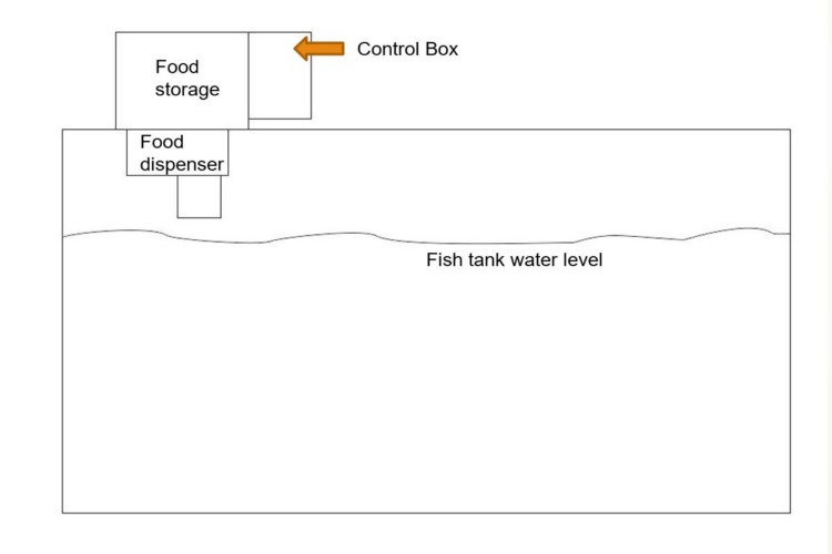
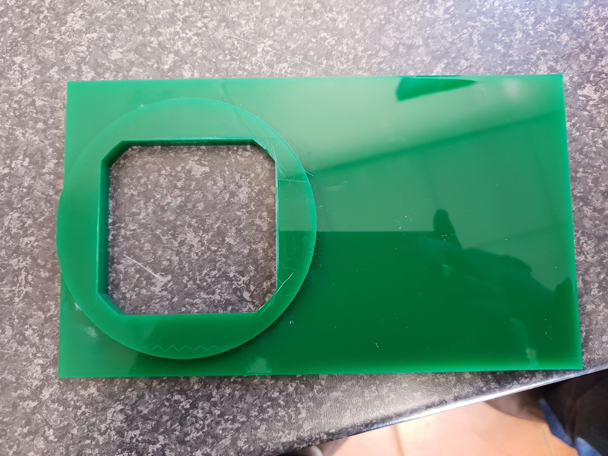
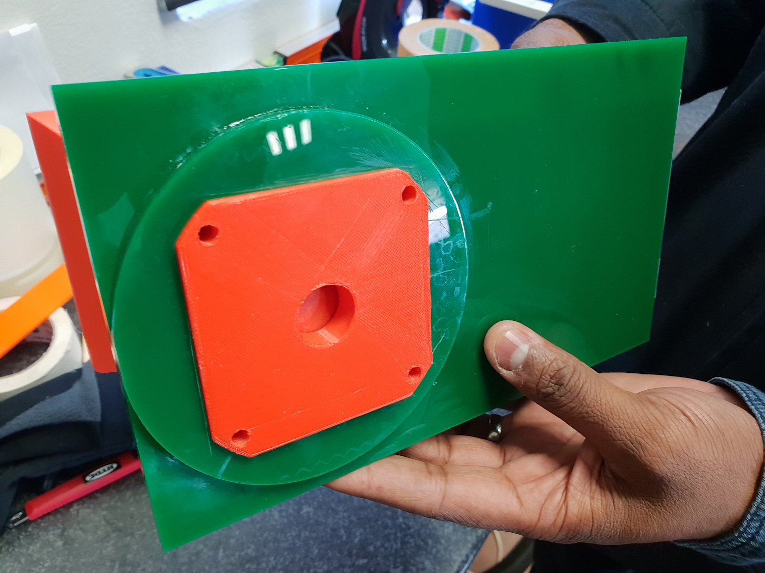
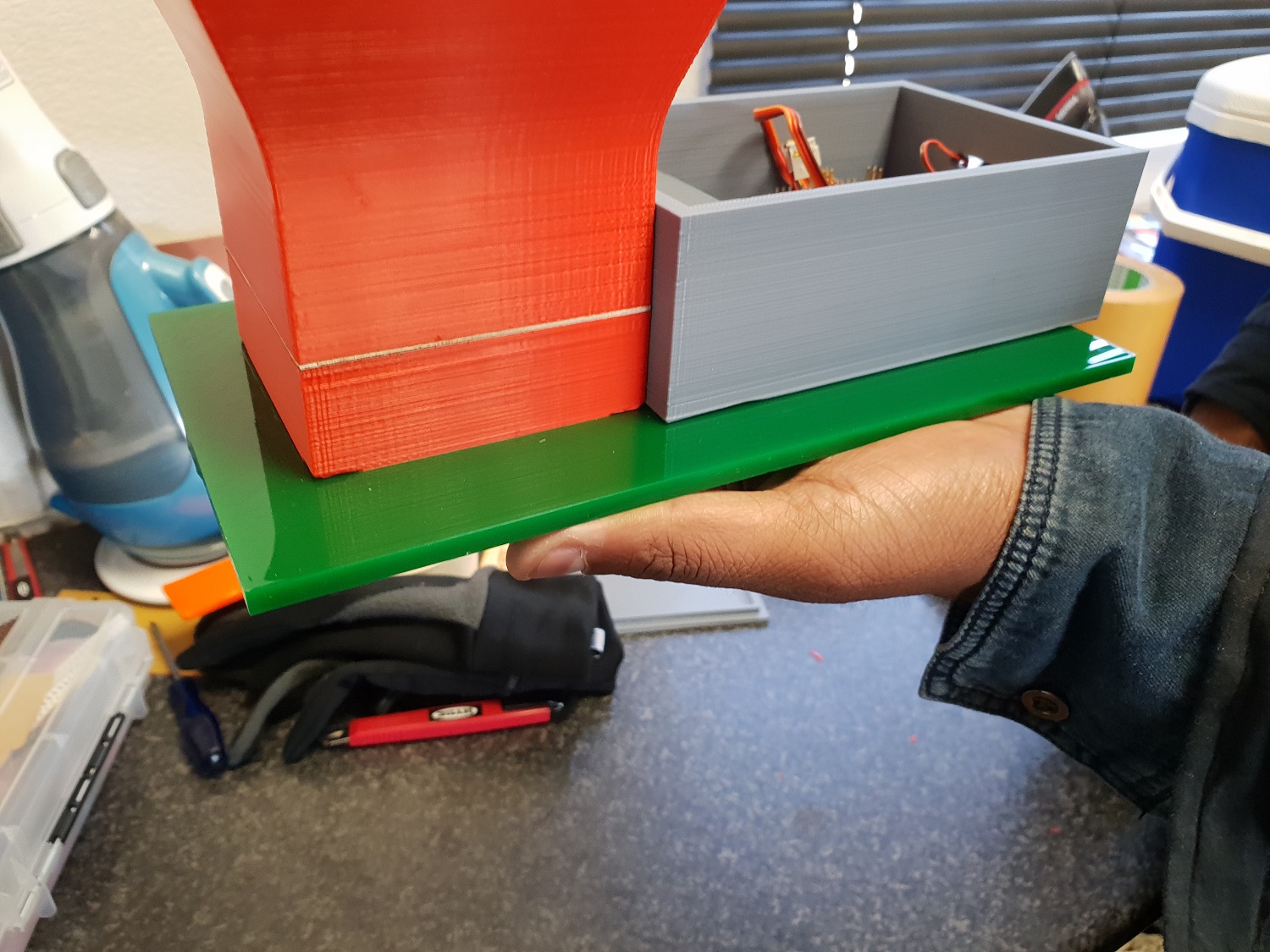
The first idea was to build a food chamber as shown in the diagram idea 1 below. In this design, the food chamber chamber will be 3d printed and a motor attached to an acrylic plates with a hole will rotate to allign with another plate with a hole at the botttom to dispense the food from the food chamber.
idea #1
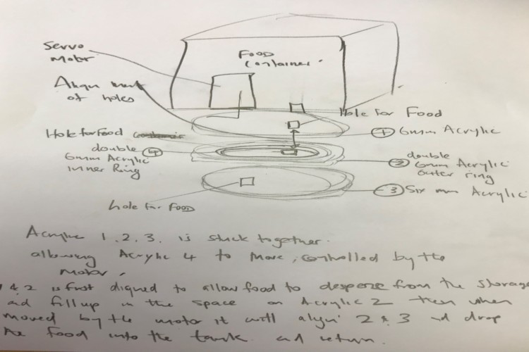
The second idea was similar, this time I will 3d print the chamber and instead of using acrylic, I will 3d print a chamber and a ball that would be connected to the servo motor and the chamber will be designed like a funnel with a hole in the middel that will align with a hole in the ball, and when the ball is turned by the motor, it will carry the food that fills up in the hole of the ball and dispense it into the tank via a hole at the bottom when in line and return to its position again to refill the dispensor. See concept sketch below.

idea 2
Block diagram of the control system
The control system will be made up of made up of three major components, the power supply unit, the reprogramable Microcontroller unit and the servo motor mechanism.
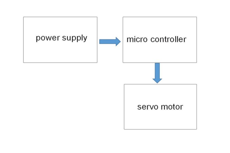
block diagram of control system
Design Process
3D CAD design of part
After brainstorming ideas with the help of my lab instrucor, I started to do my first prototype. I decided to go with option of idea #2, the dsipenser with the ball at the bottom. I decide that it would be easier for me to 3D print the container. Using 3D max, I started the design of the container as per my sketch. and once I was done I decided to save the files in STL format and used the 3D printer to print them out. see photos of first prototype below.
First Prototype Design
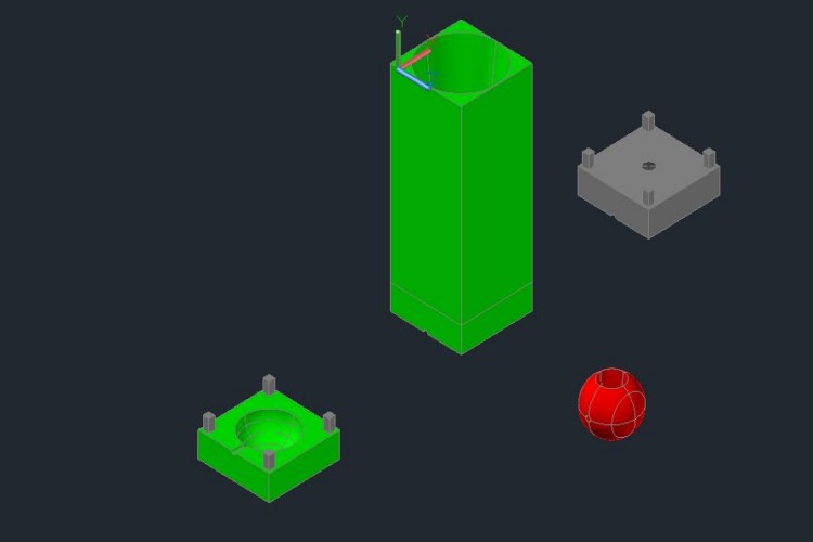
First prototype CAD design using 3D max
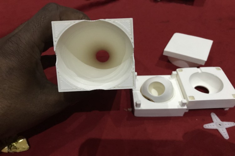
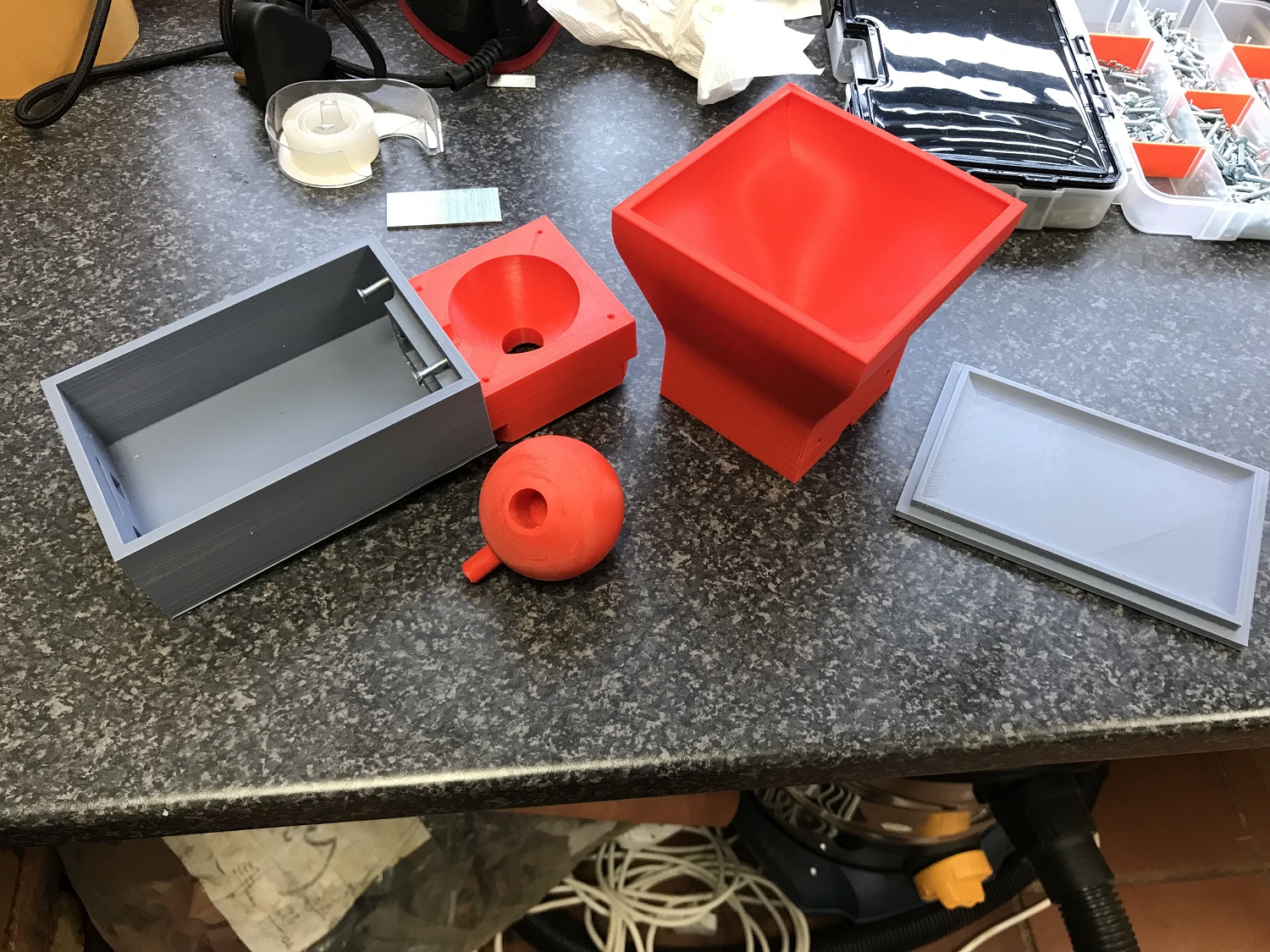
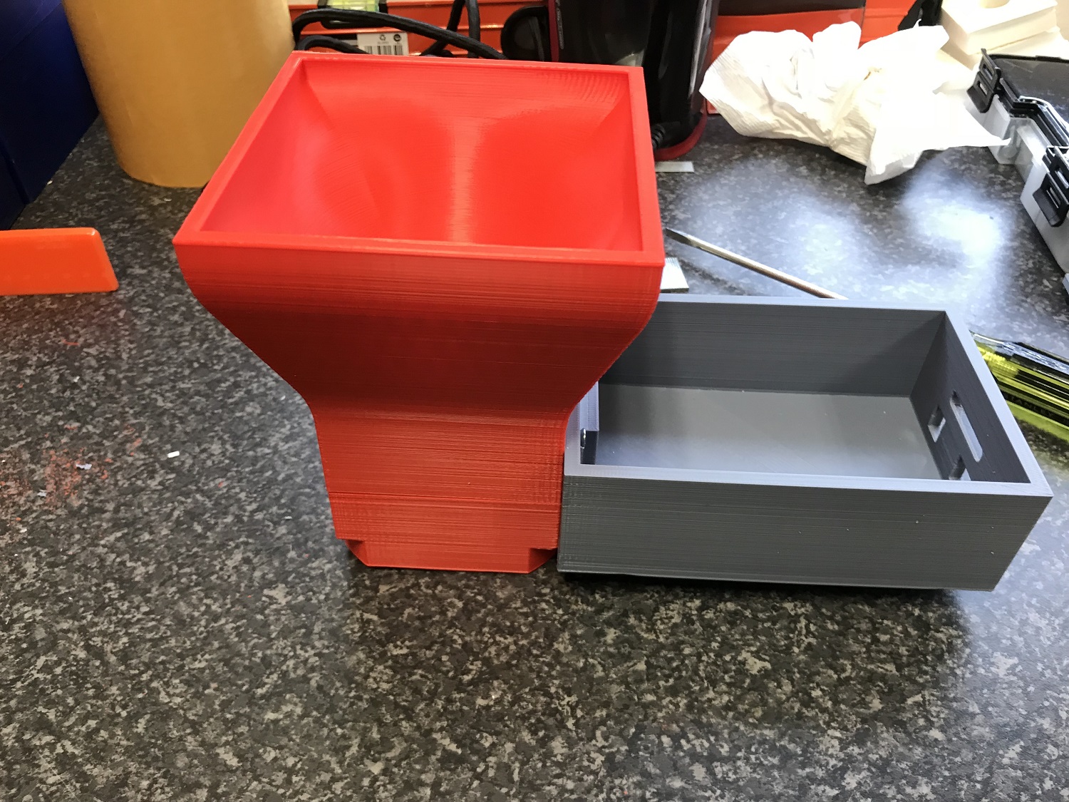
3D printed parts of first prototype
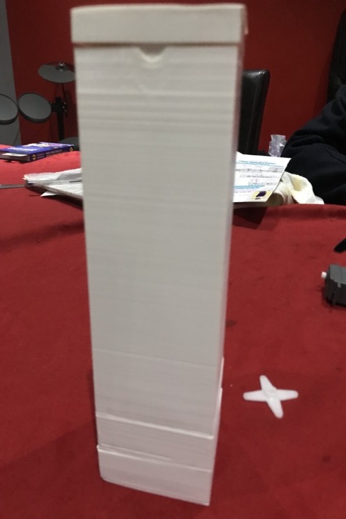
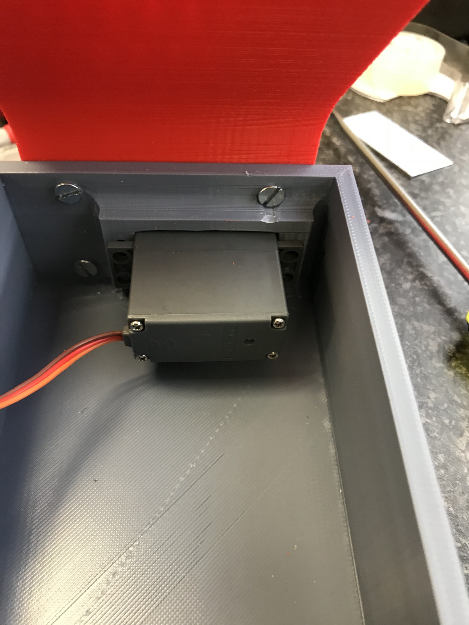
Assembly of first prototype
Second Prototype Design
After making my first prototype, I realised it was not very practical after discussing it with my lab instructor. I noticed did not take into accoount where the motor would be set and how it would be housed and protected, I also did not take into account where the control unit will be located and the averall dimension of the system with respect to the components I will be using and the tank itself. So I decided to try another design. With the help of my Lab istructor, we came up with a diferent disign and took into account all the necessary measurments and then using the solidwork, I designed all the parts, assembled them and rendered the final and exploded view of the assemble. See photos below.
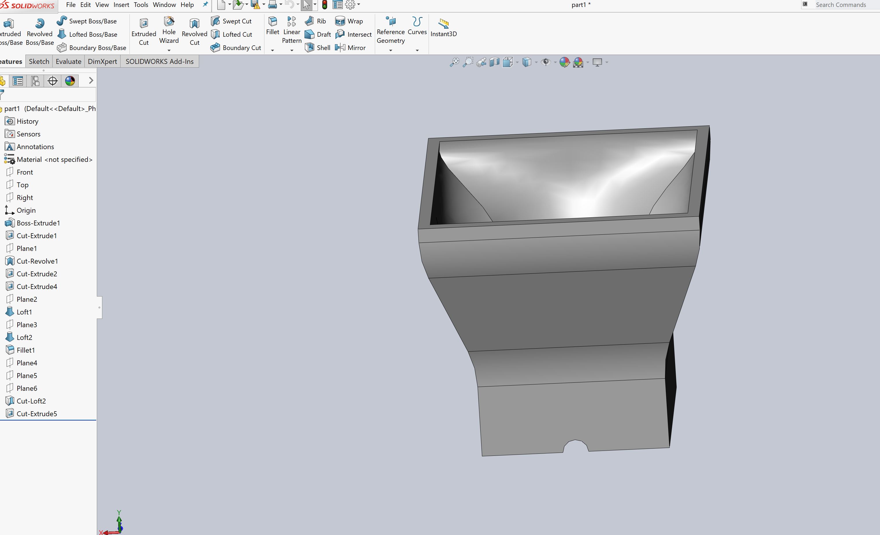
Food chamber
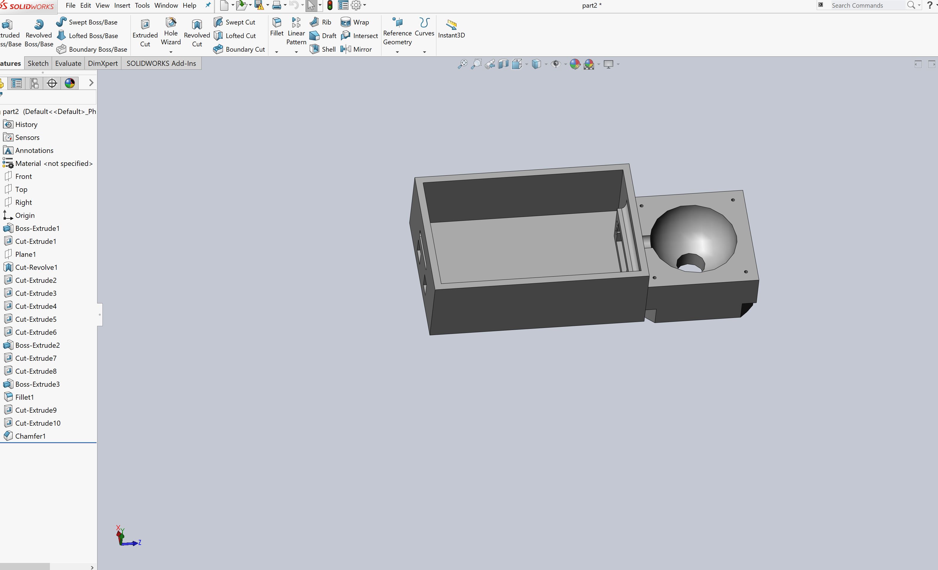
Control unit housing with part of the dispensor housing
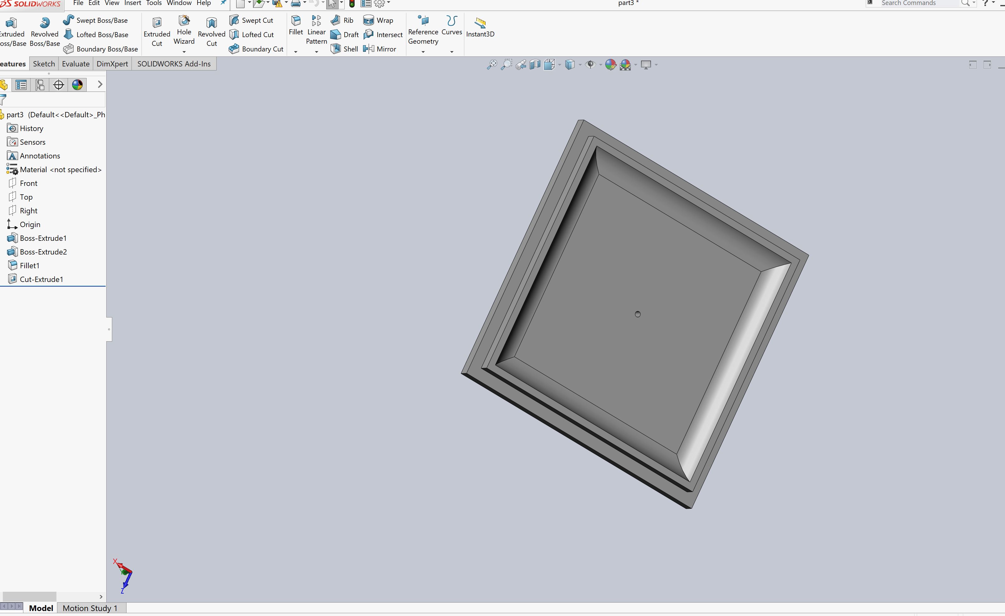
Food chamber cover
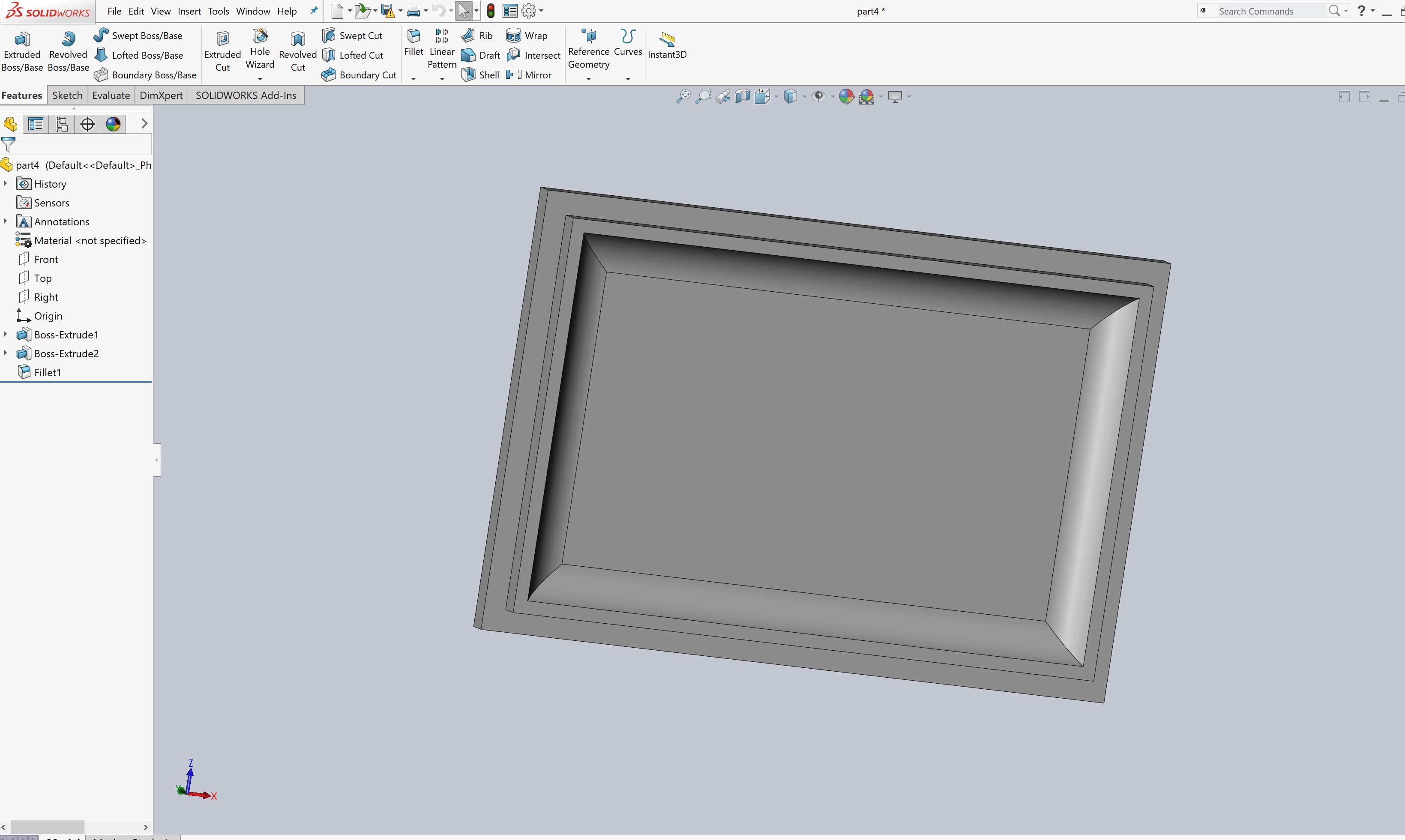
Control unit housing cover
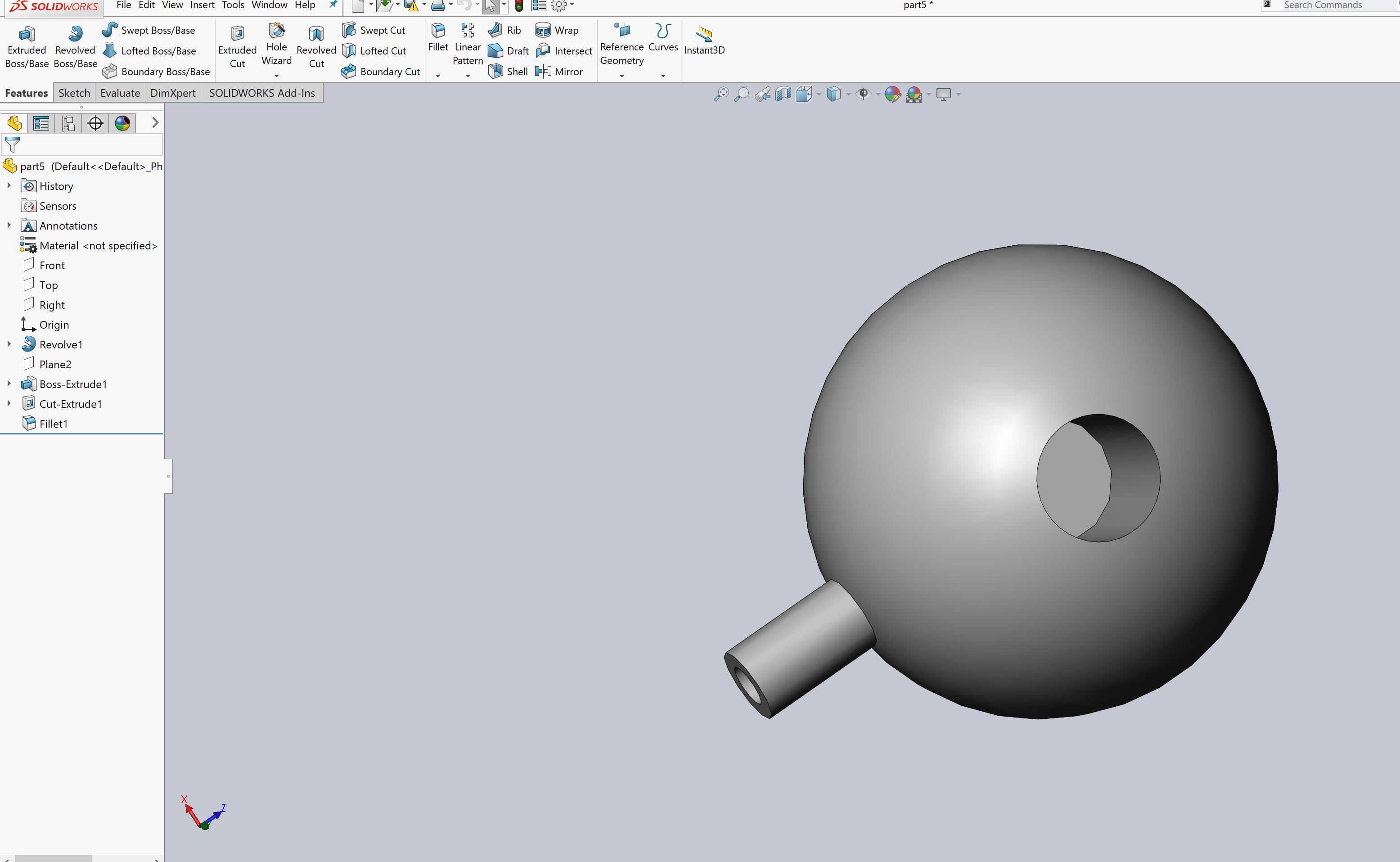
Dispensor Unit
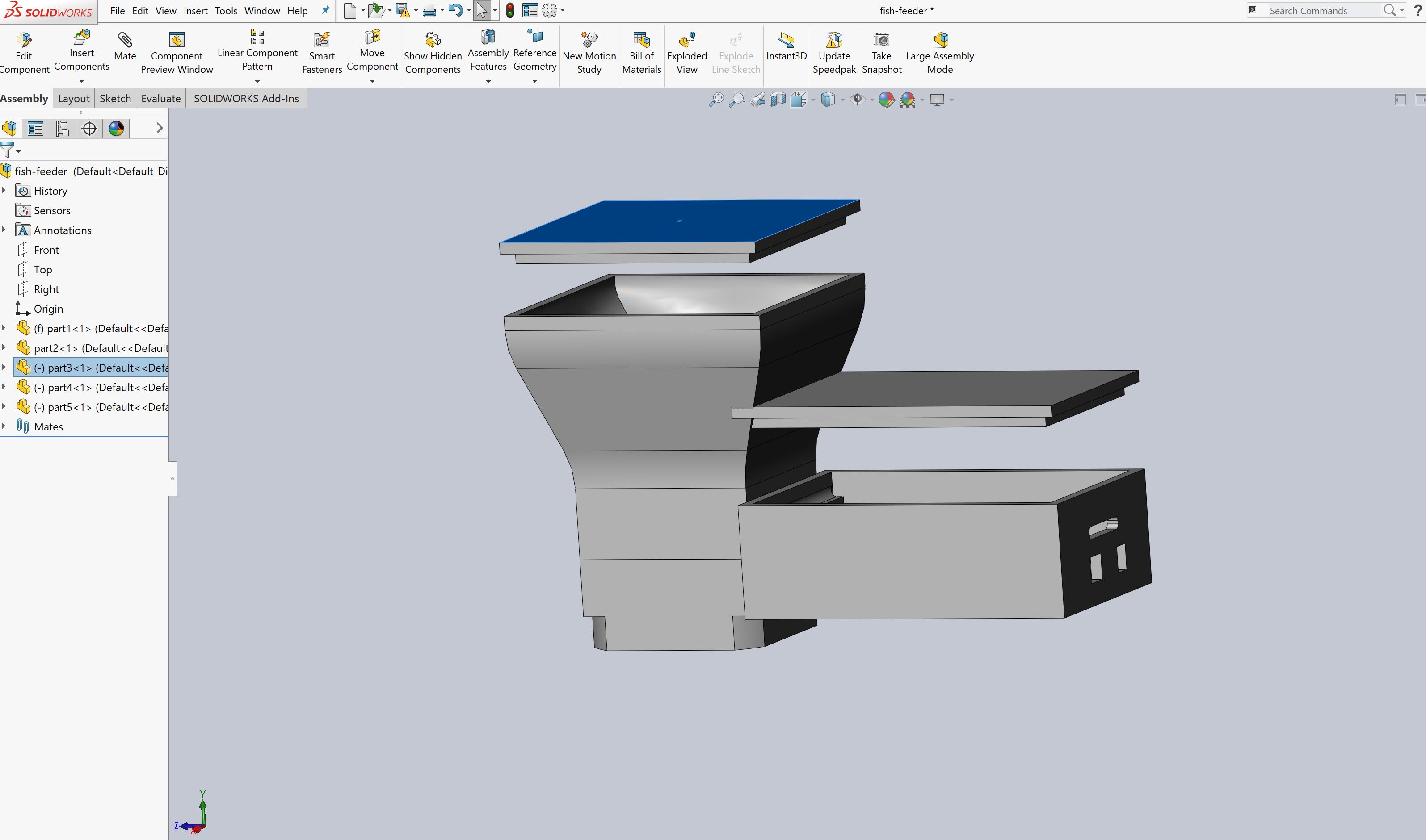
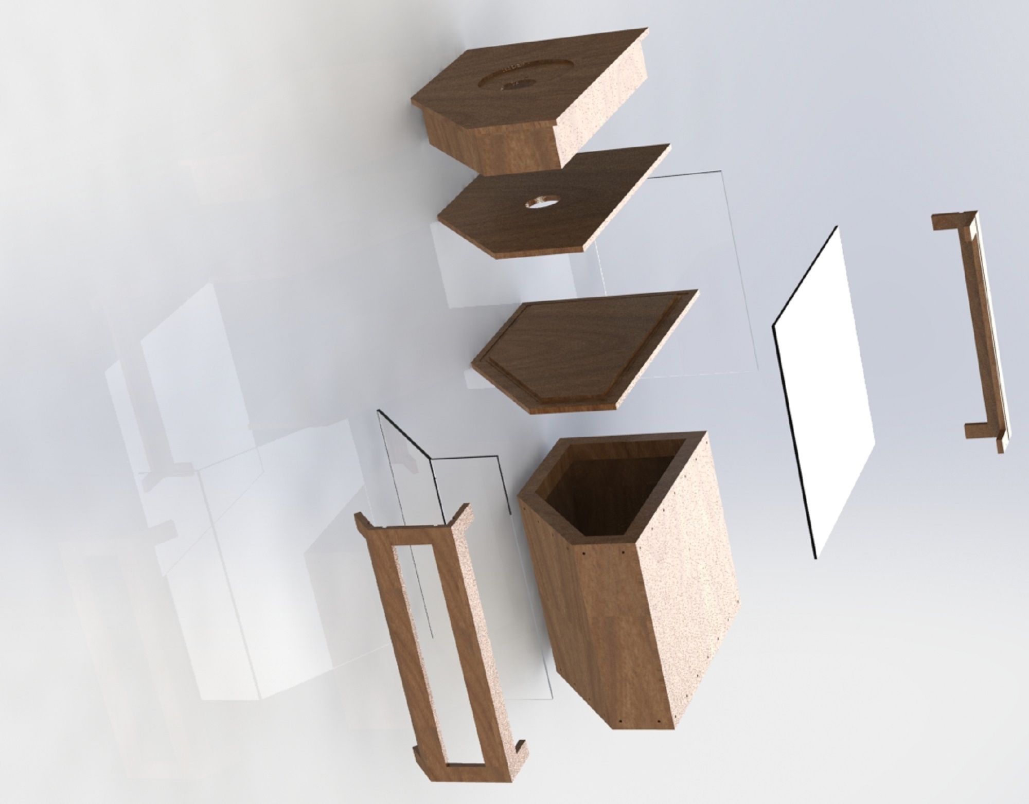
final assembly
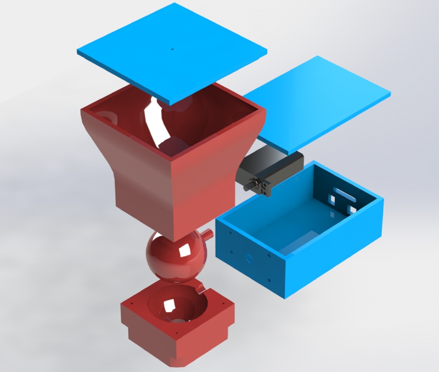
final Final Render
click here to download solidwork files
3D printing and assembly of Parts
I then created STL files after assembling the part to make sure they fit correctly and Using the sindoh 3D printer this time round, the sindoh 3D printer is much better as its boxed and it mentains the atmosphere temperature while printing, I started to print the parts and then assembled them after printing.
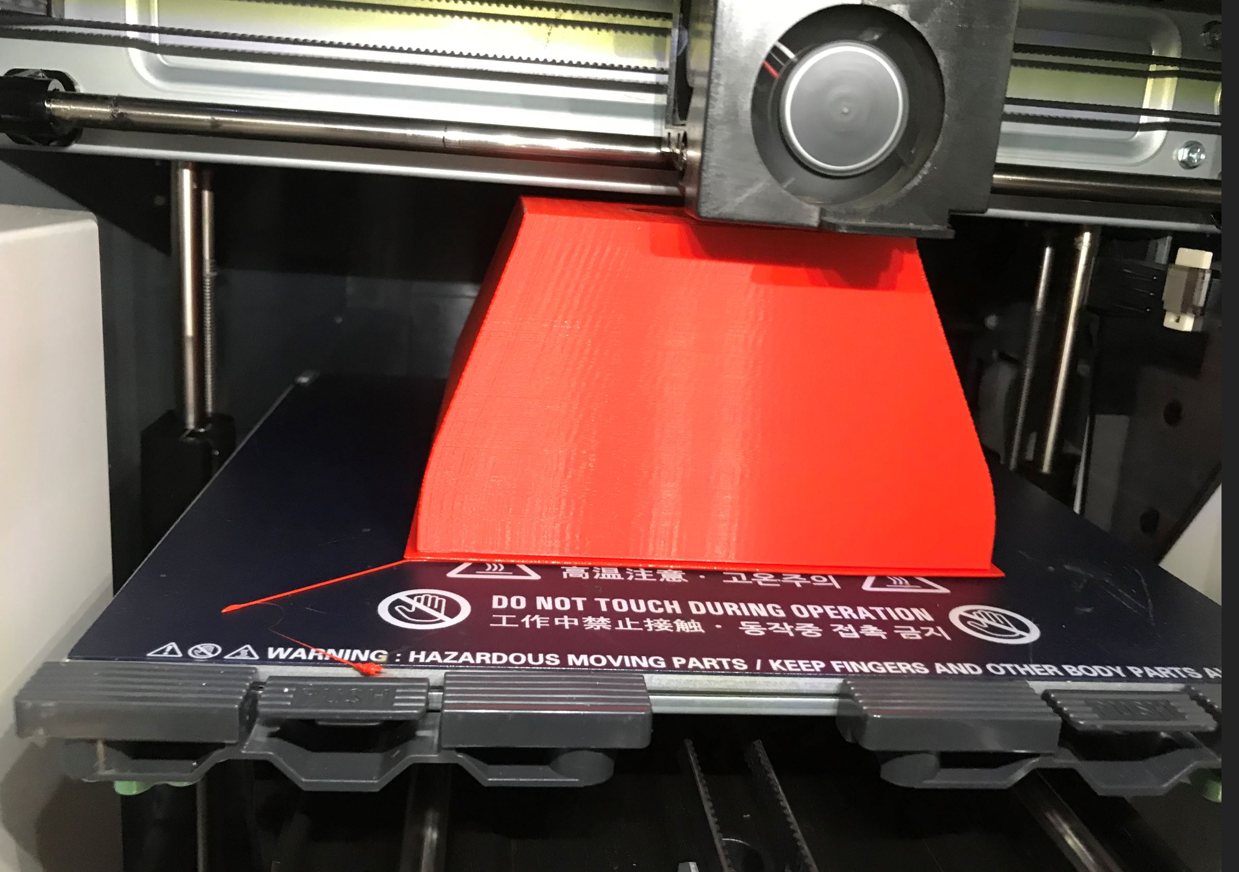
3D printing
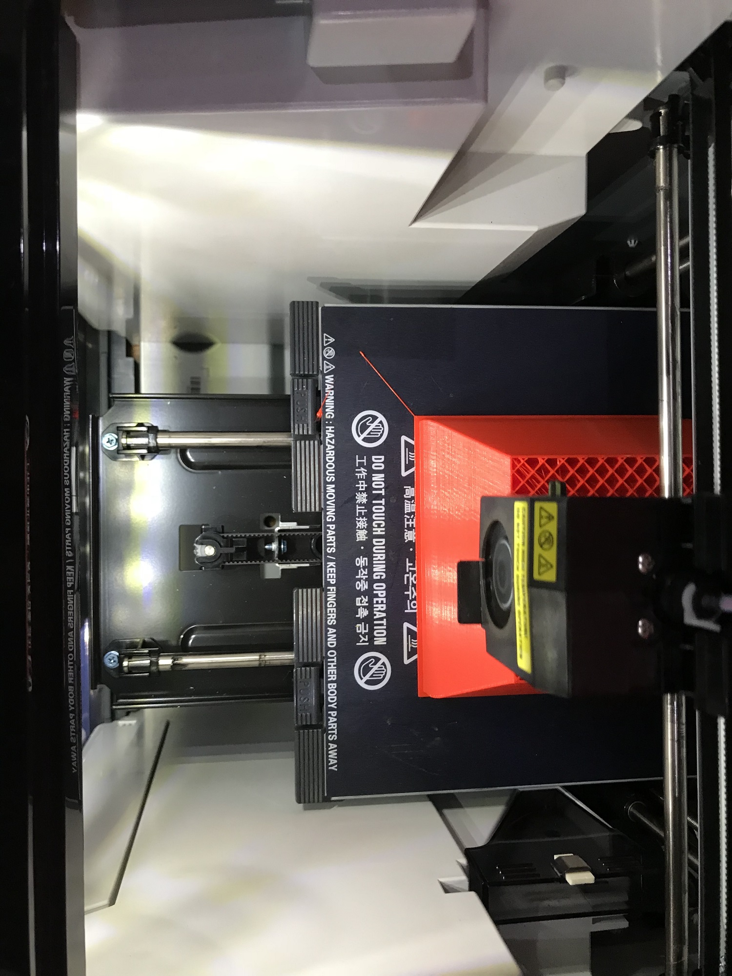
3D printing
assembly of parts
assembly of parts

assembled parts
checking if the servo motor would fit in properly
Base plate design Using corelDraw
I then designed a the base plate for the feeder to sit on using corelDraw and then cut it out with acrylic using the laser cutter. See photo and files below.
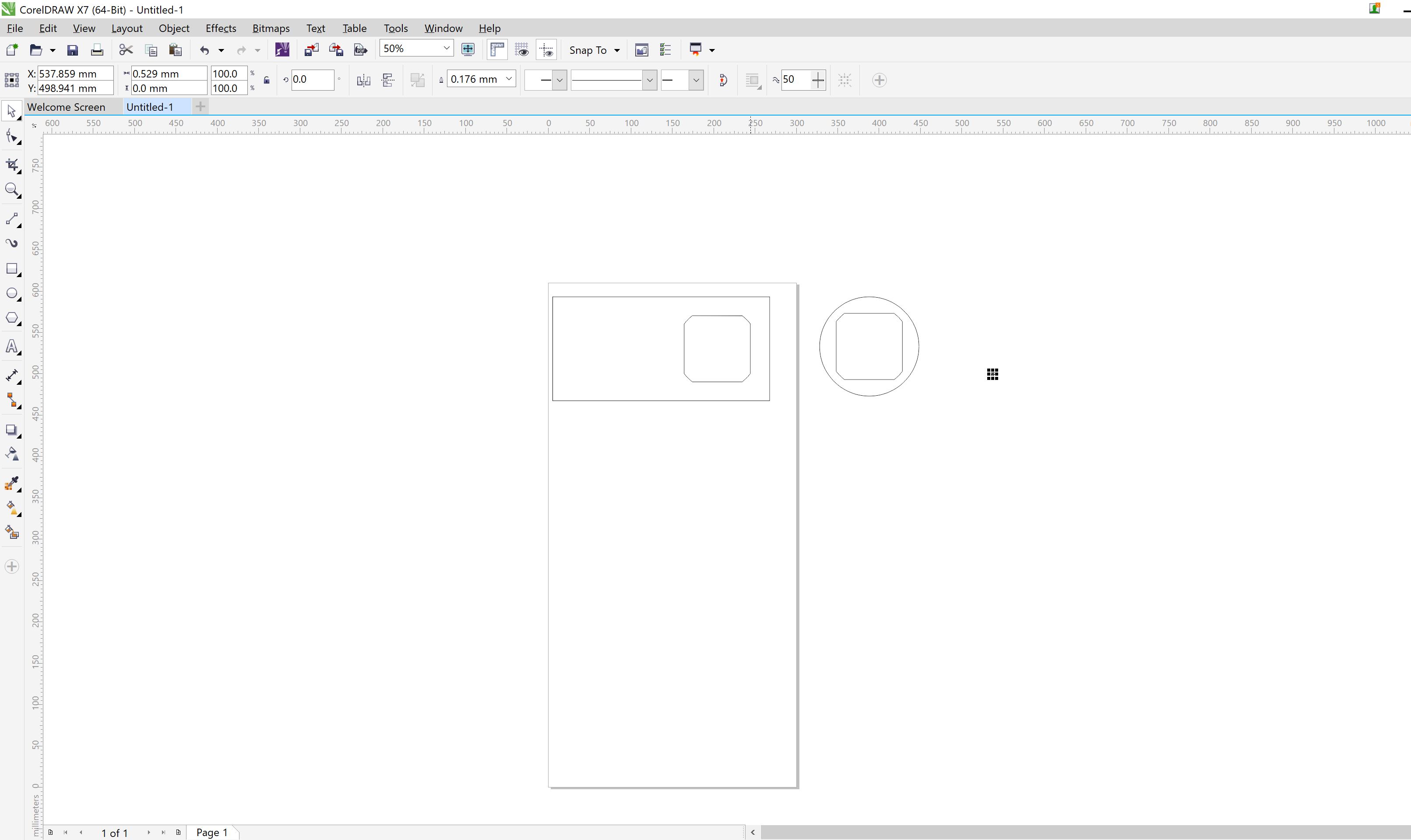
Base plate design
Base plate cutout
Base plate cutout assembly
Base plate cutout assembly
Design and Building of Fish Tank (Extra Project)
Having started my fab academy last year, I desided to use my Fish tank as part of my final project design. The fish tank which I built using sleeper wood, was designed using solidWorks, processed and cut using the ShopBot. Below are the photos showing the breef process and and CAD files for download.
Fish tank render

Putting wood together
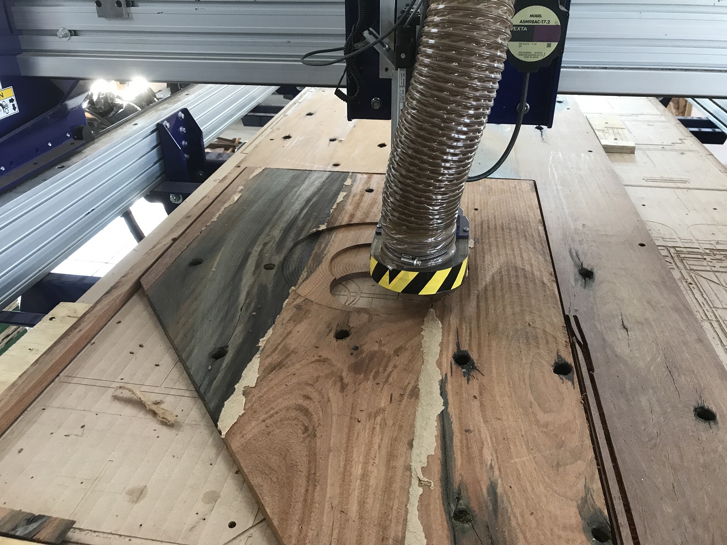
Cutting parts using shopBot
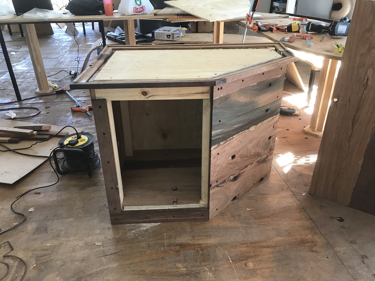
Assembly parts
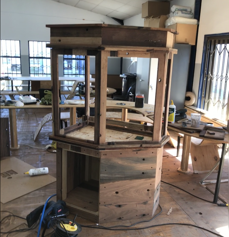
Assembly parts
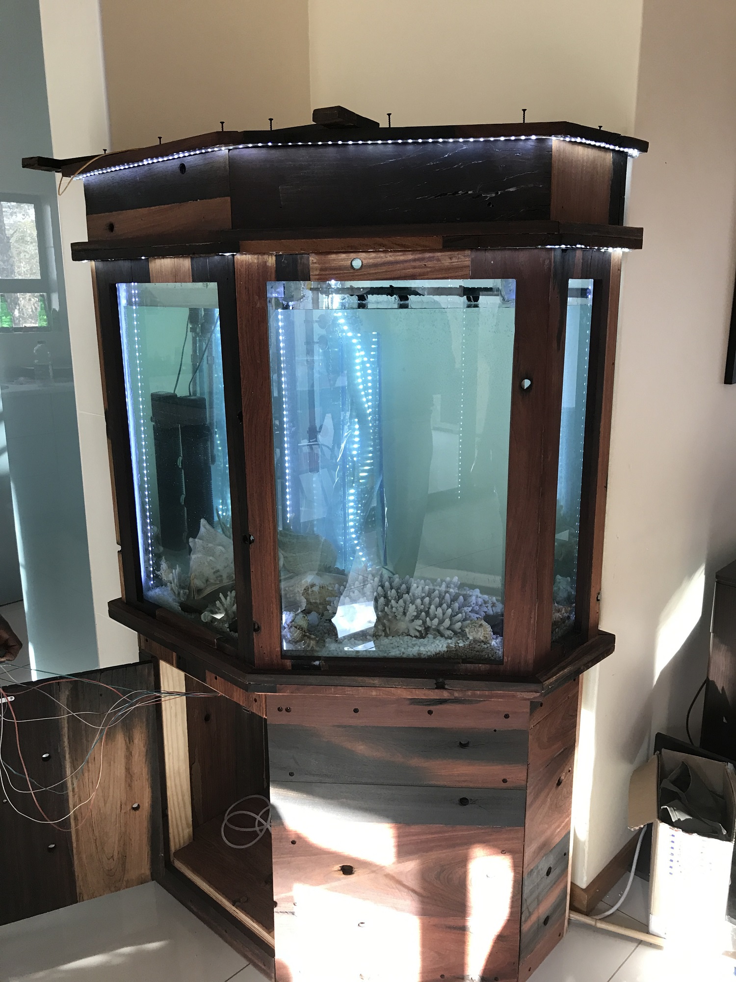
Final Fish Tank
Design and Building Control Board Unit
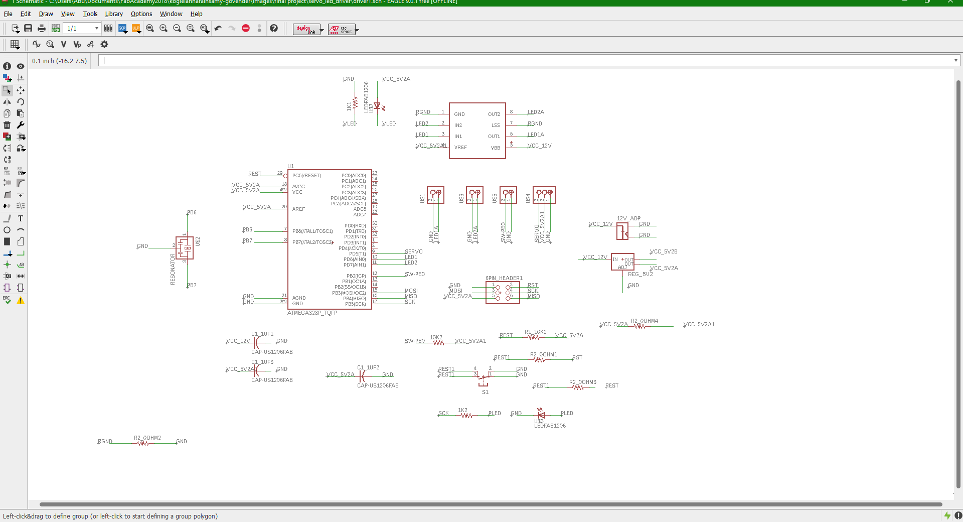
I started my control board unit design by building a sheild for my servo and light control and using the arduino as the interface board to control the servo and the lighting system. But soon realized I was supposed to build my own control system from scratch, so I decided to design and build my own Microcontroller control unit using the ATmega328p.
Using the eagleCAD program, I designed the board and then generated the PNG images og the traces and interior files to be processed and milled using the roland SRM-20. See Photos and files Below.
First Control system design building a Shield with arduino.
After making the sheild with the Arduino, I programmed it and tested it and it worked but then I was not able to use it because it did not meet the requirement. Below is the test demo of the feeder mechanism working with the sheild.
The programme is to control the servo motor When it is reset, the servo moto goes from 0degrees to 178 degrees and has a delay of 15 seconds before it reurns to it orignal position. the delay command allows it time for all the food in the chamber to fall into the tank and when it returns to its orignal position, the LEd which is connect to PIN 2 turns on.it waits for a specified time delay and turns off
video demo of Fish-Feeder with sheild
Final Microcontroller Control Unit using Atmege328p.


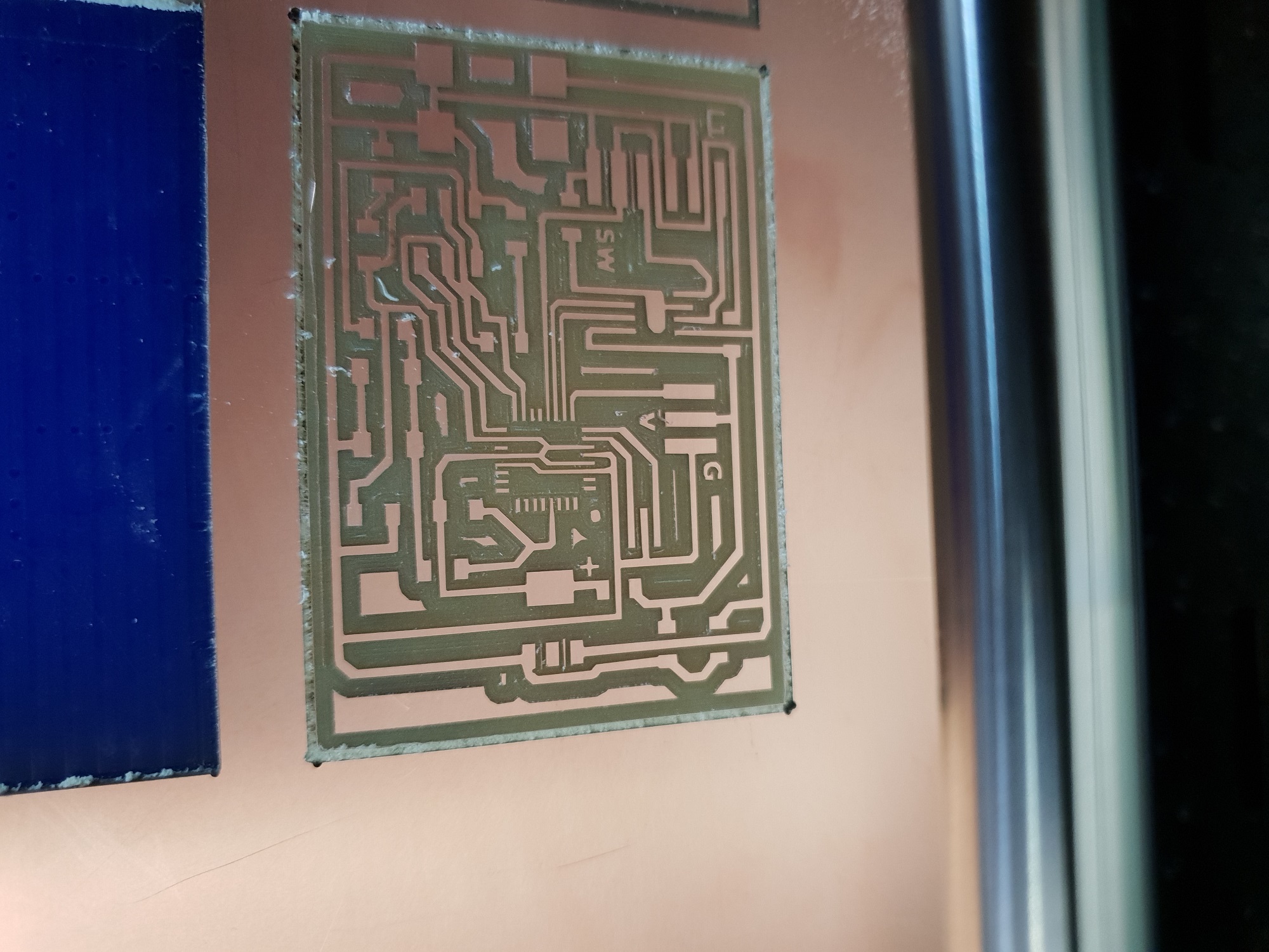
Milled Board
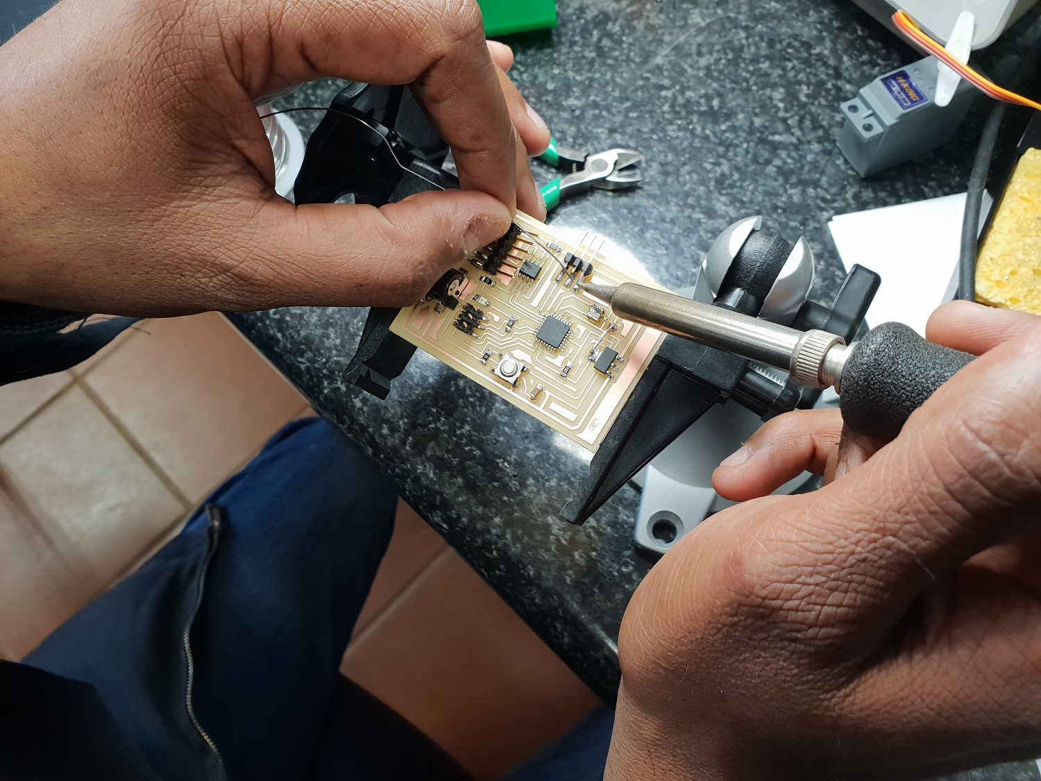
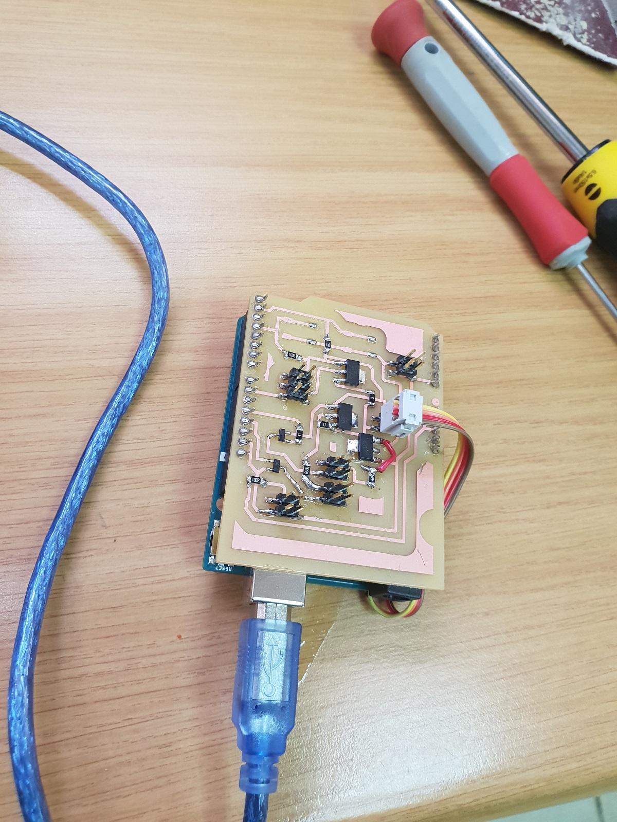
Soldered Board
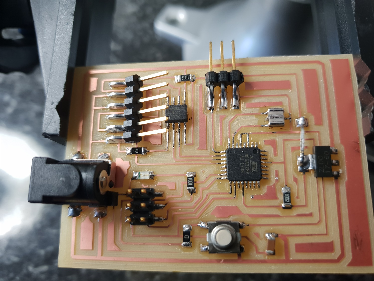
Finished Soldering Board
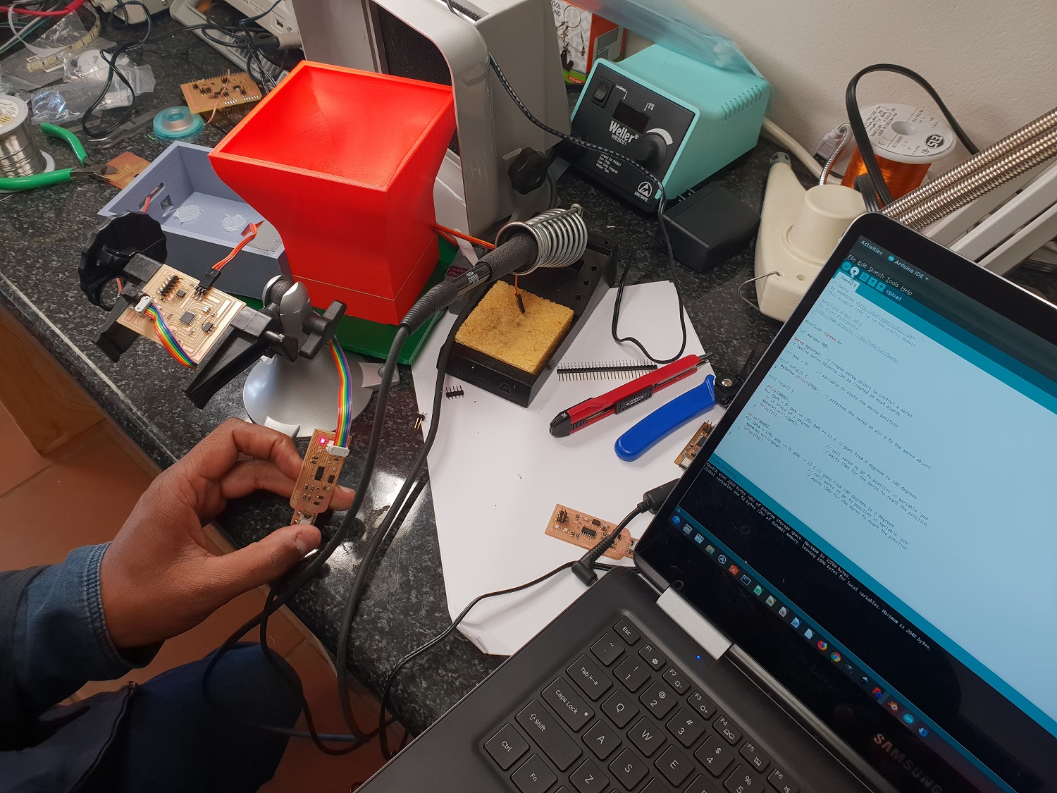
Programing Board with Test Program
Running a test code with Atmega328p Control unit
After building the new control unit with the Atmega328p microcontroller and programming it with the test code, I runned a demo by connecting it to the servo motor and series of LEDs. See test demo video below.

Test Program with Servo and led
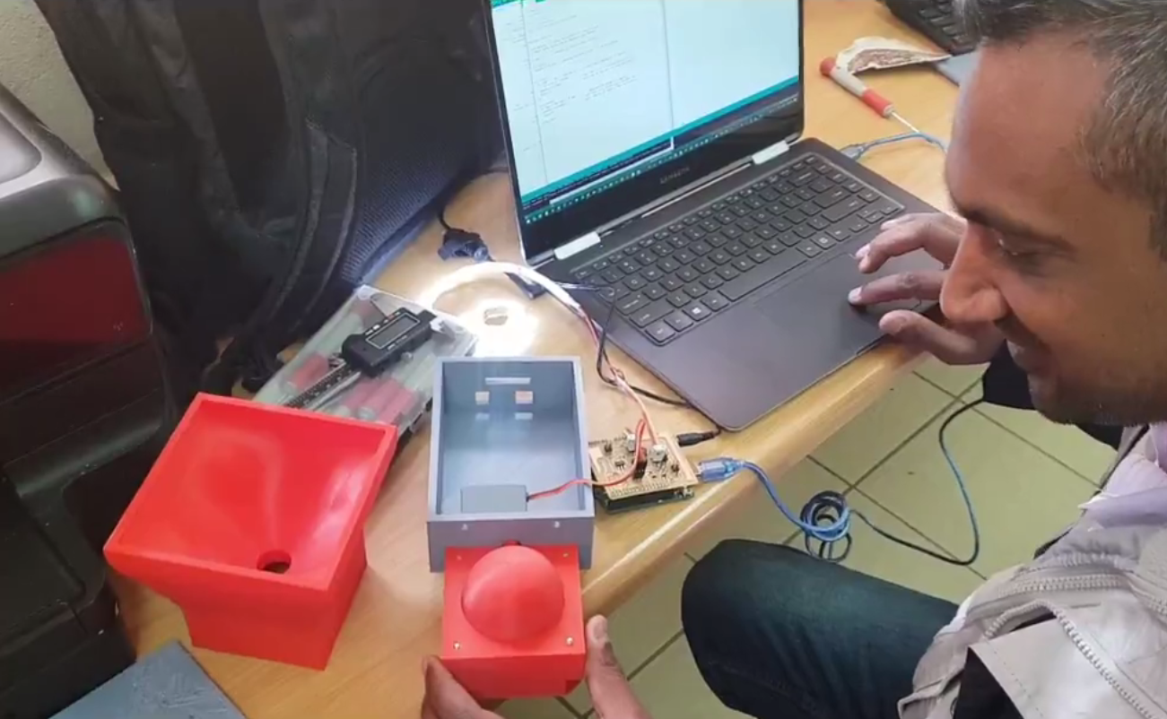
I then performed a test run with the assembled Mechanism. See demo Video below.
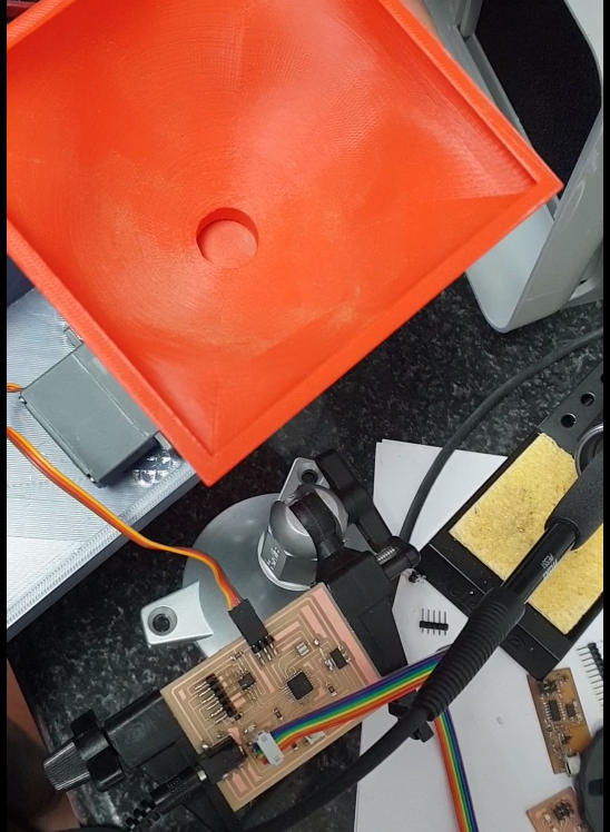
Test Program with assembled mechanism
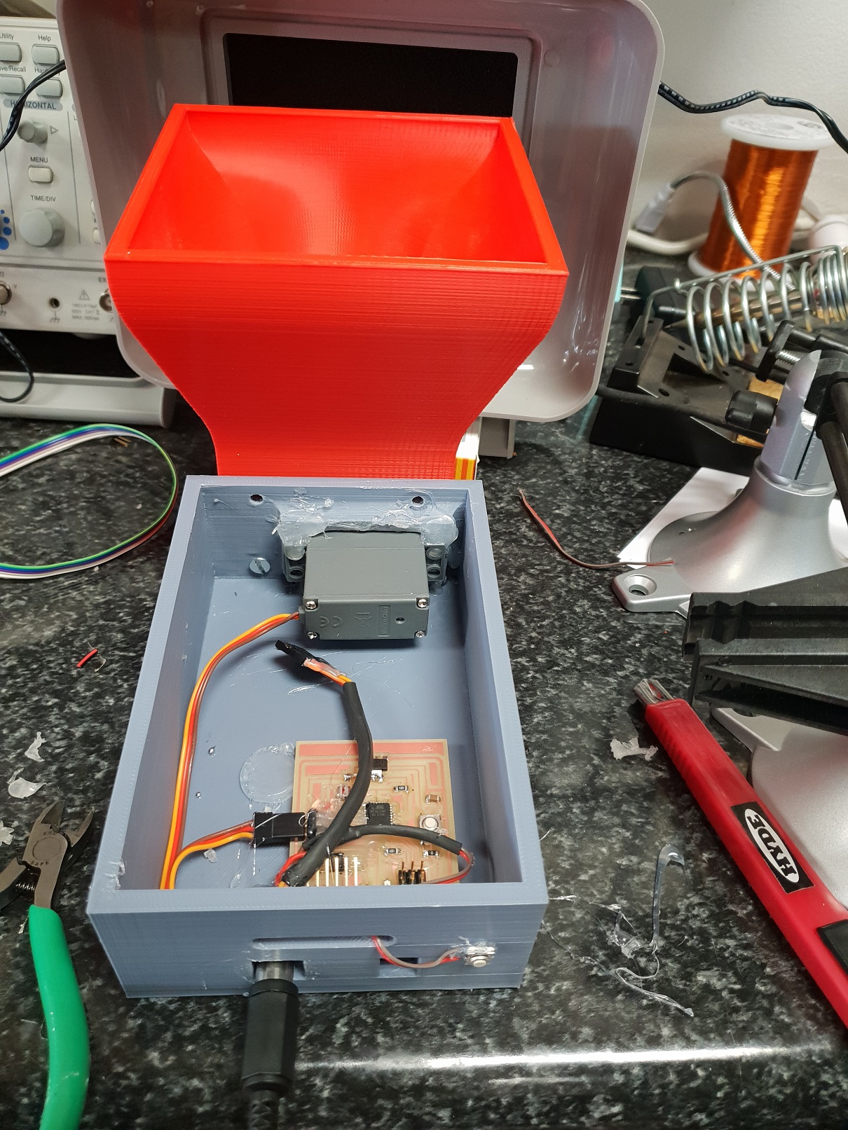
Assembled Control Board in housing
Video below shaows the compiled demo of the Fish Feeder