This week was next step to the electronics ,study about "sensor" was a different experince .Neil gave some ideas about the different sensors then I selected motion sensor for going forward with htis week assignment ,In week class neil already gave the full ideas and designing of the board ang programming code. Here we want to show the input of our sensor with some programming softwares
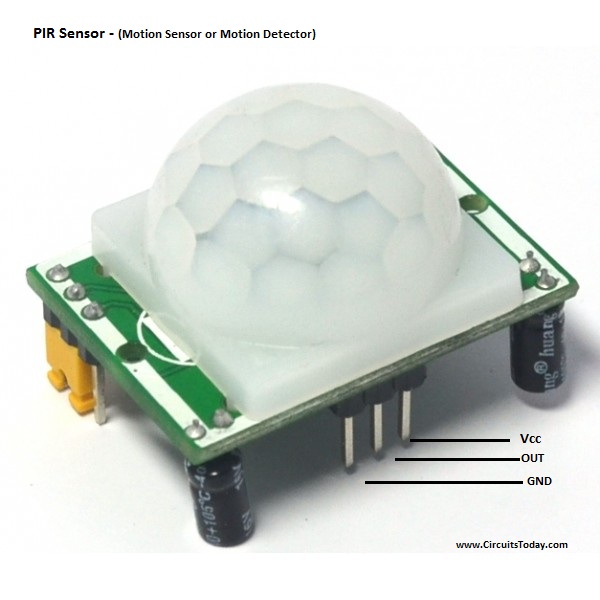
I selected the motion sensor "PIR -sensor"(Passive infrared sensor) which gives the out by recognize the motion of a object ,this electronic sensor which measure the infrared light radiating from a object
Group assignment
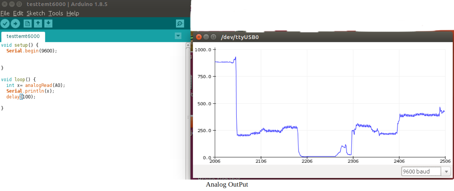
The sensor is a module or a chip that observes the changes happening in the physical world and sends the feedback to the microcontroller. Microcontroller accepts two types of input they are digital and analog Analog sensors sensed the external parameters and given output in a range of 0 to 5V. for example if we are using LDR sensor module. In 9.00am it gives an output of 3v, and 11.am output is 4v, and 1 pm output is 4.5v, and in night output is 1v. it shows that analog sensors measure the quantity not only the presence of something.
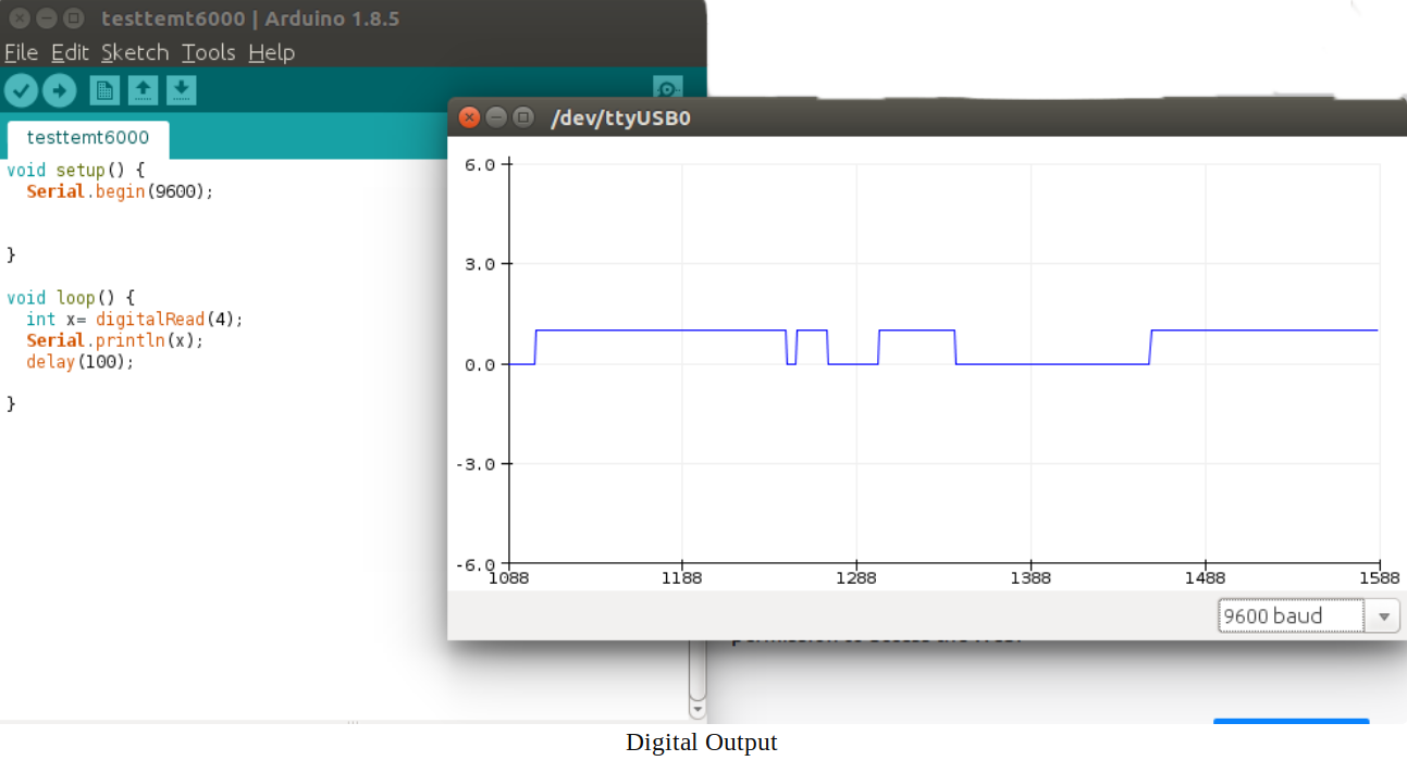
Digital Sensor produce discrete values (0 and 1). Discrete values often called digital (binary) signals in digital communication.for example if we are using PIR sensor .it gives output of 3.3v when motion is detected and 0v were no motion detected. Here We used Arduino connected with PIR sensorand run the code and made the plot.
1.DESIGNING OF BOARD
Here I used "Eagle" software for the designing of my board as I familiar with previous WEEK I decided go forward with Neil's bord with my own drawing that was a tutorial to me .when making a"PIR sensor" board we want add these components ,after seeing that board I draw it self using Eagle
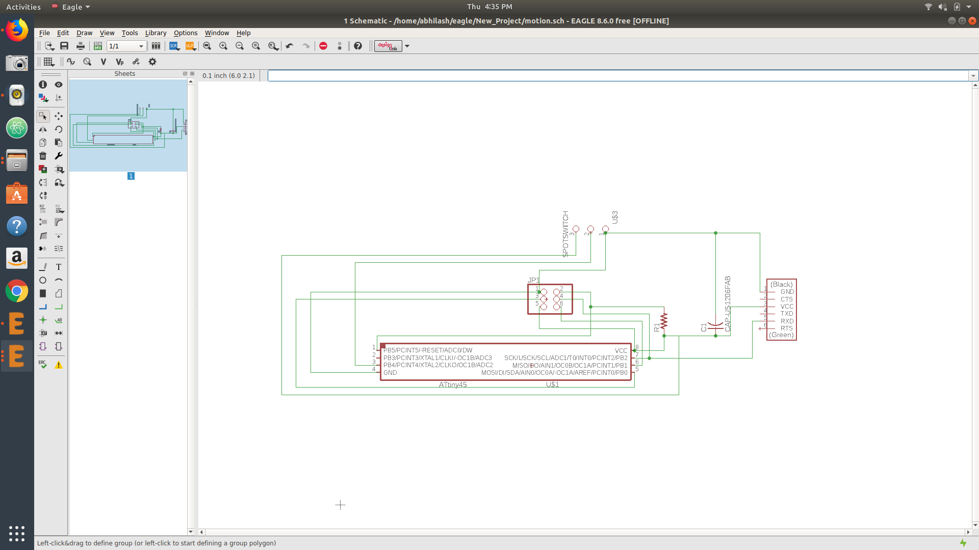 schematic diagram
you can download .sch file of my board
Here I used ATtiny45
FTDI pin
2*3 Header pin
10k ohm Resistor
1mF capacitor
Additionally add 3 slots for adding sensor module to board ,here the 3 slots are connected to vcc,GND,and out from the sensor
After giving the complete Rout I switched it into the board after arrainge it I go forward with Auto route by giving the clearence "16" and trace thickness as "18" then "AUTO ROUTED" here I got 100% toprout at the time of routing so I decided to go forward with that
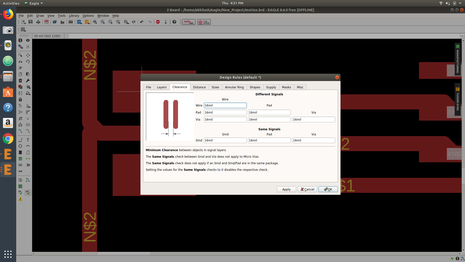 addding clearence and size
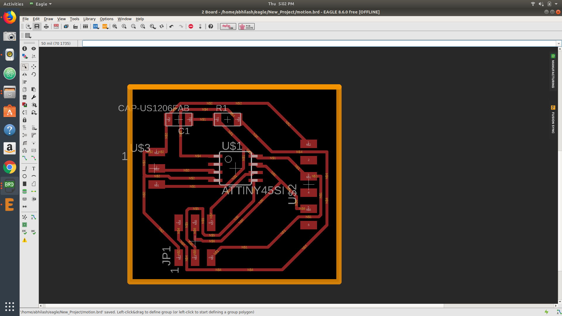 My board after auto rout
After Designing of the board I want to export it as .png file for milling of the board ,So here I expor ted my board into two .png file for mill and cut so I selected "LAYER TOOL" and make all as sellect none - after that I selected "Top & Pad" first for milling and second(Already gave the outline thickness as 33 mill here the 1/32 bit can make path for cut through giving "properties < width") select "Dimension" for cutting In each time I exported it as as .png by giving monochrome. you can download my board
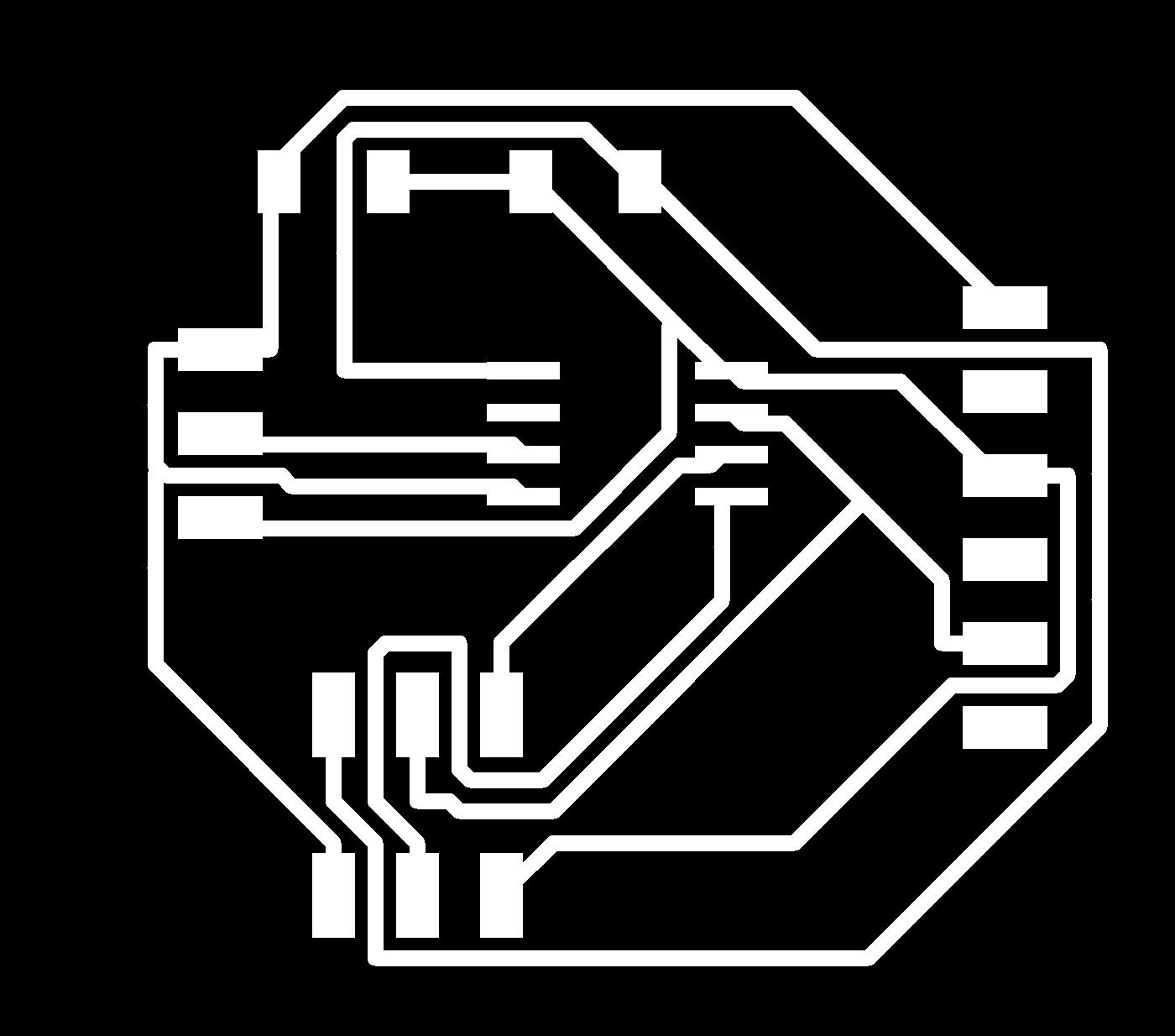

Trace.png image can download here
Cut.png image can download here
.SCH file you can download here
.BRD file you can download here
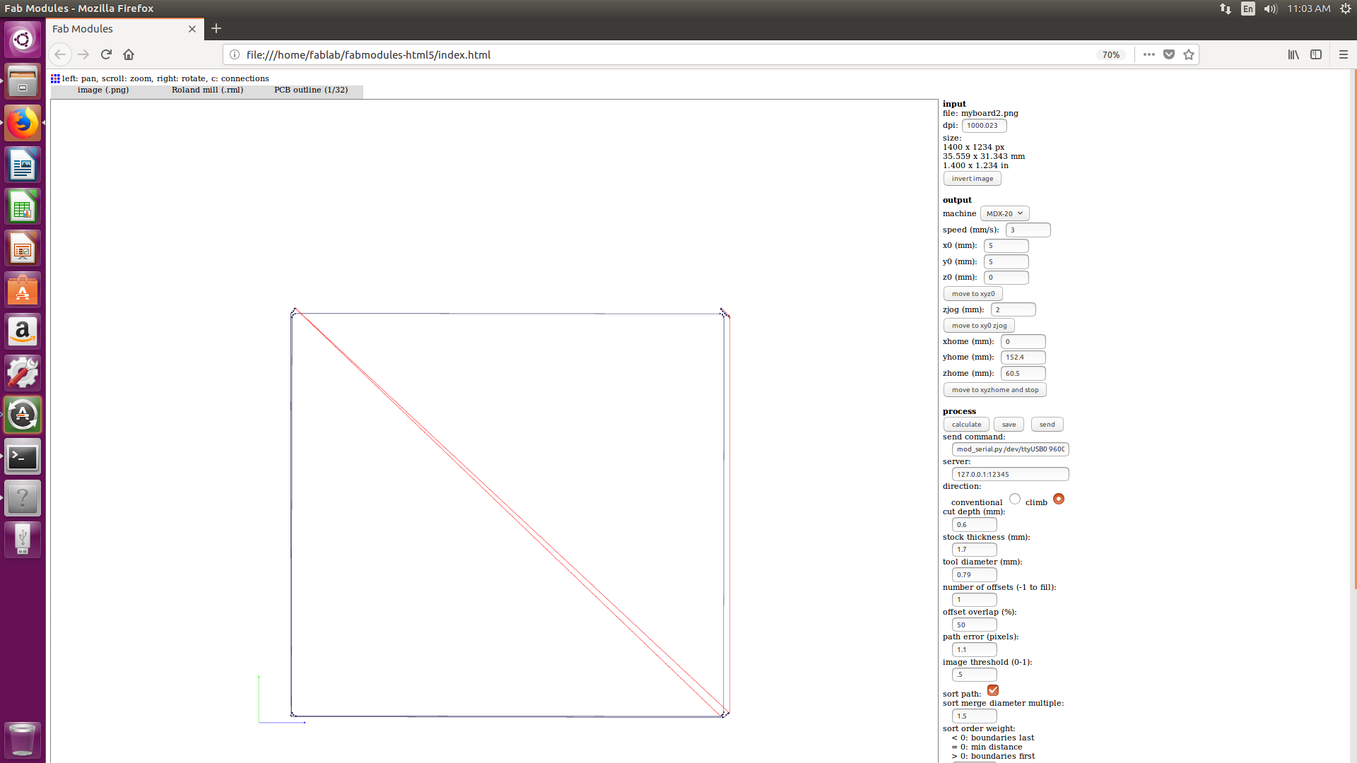
2.MILLINING OF BOARD
I am very femiliar with milling process here I am very interest to operate the milling machine , so this stage I felt bit easier after opening Fab module I opend my png image in that here first open the image that going to mill then I select the 1/64 BIT these bit is generally using for milling in our machine the I adjusted the "X,Y,Z" origin after giving speed=3 I sent it into mill (before setting the origin I fixed the bord on the bed ) .Then used 1/32 bit for outline cutting and with the same origins and speed .This time I got a clear path that bit can moves
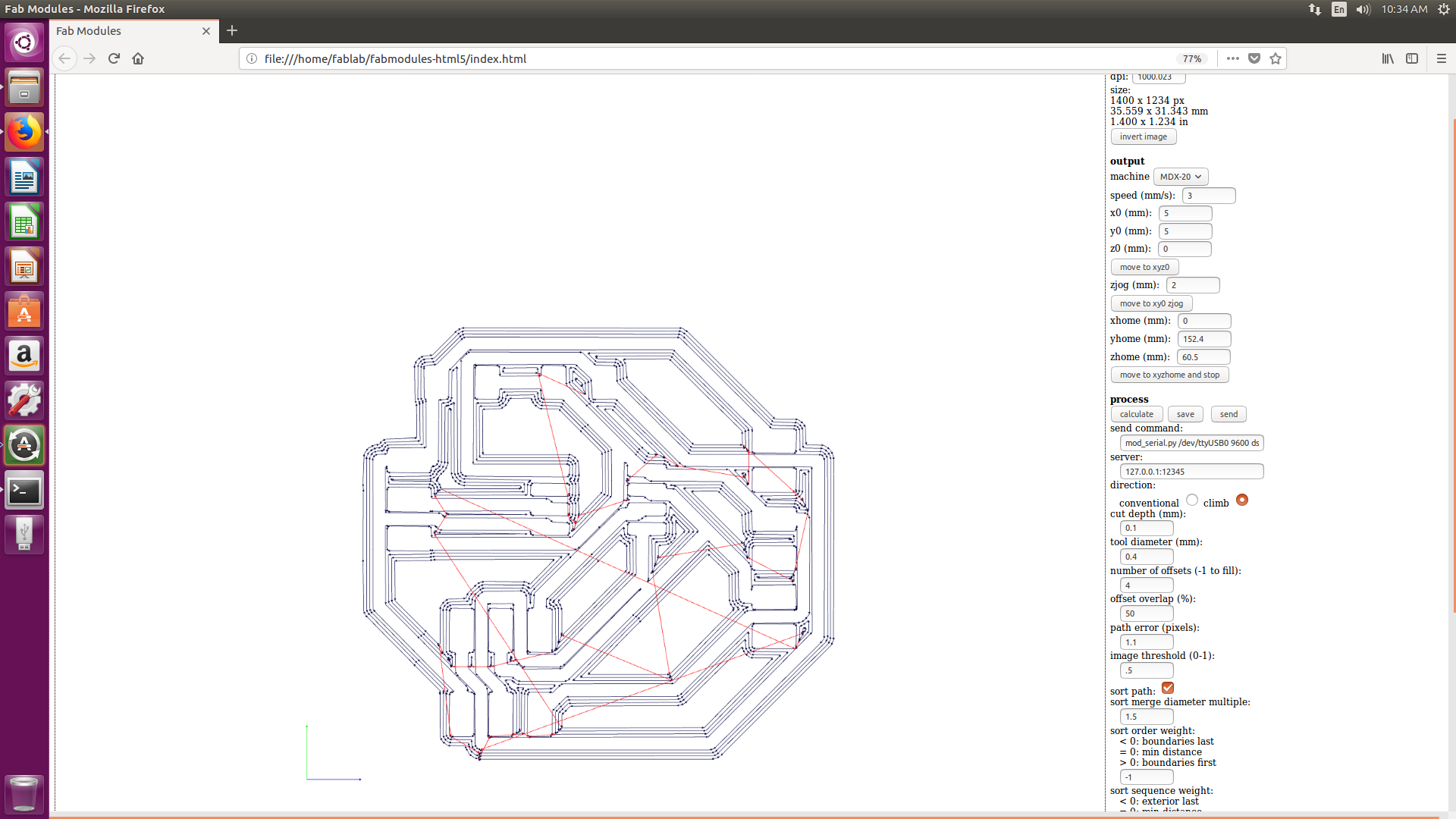
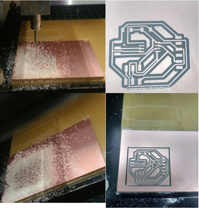 milling and cutting process
3.My board
The Board is milled out then I picked all the components that my board want, Then I solderd all the components each to my board also connect a pin slot for connecting the sensor to my bord after that I checked my board with multimeter for fing all the connection is good
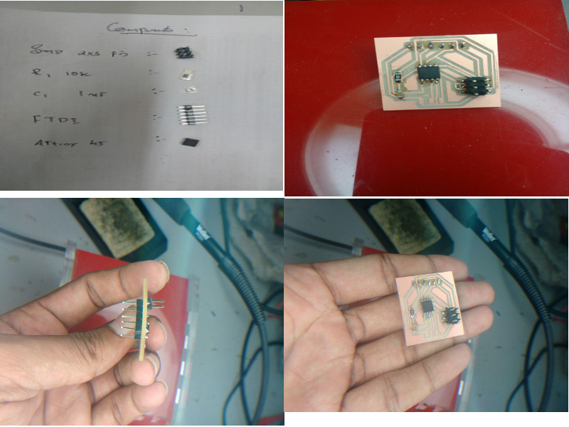 here is my board
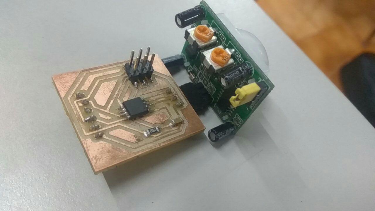 Board With sensor
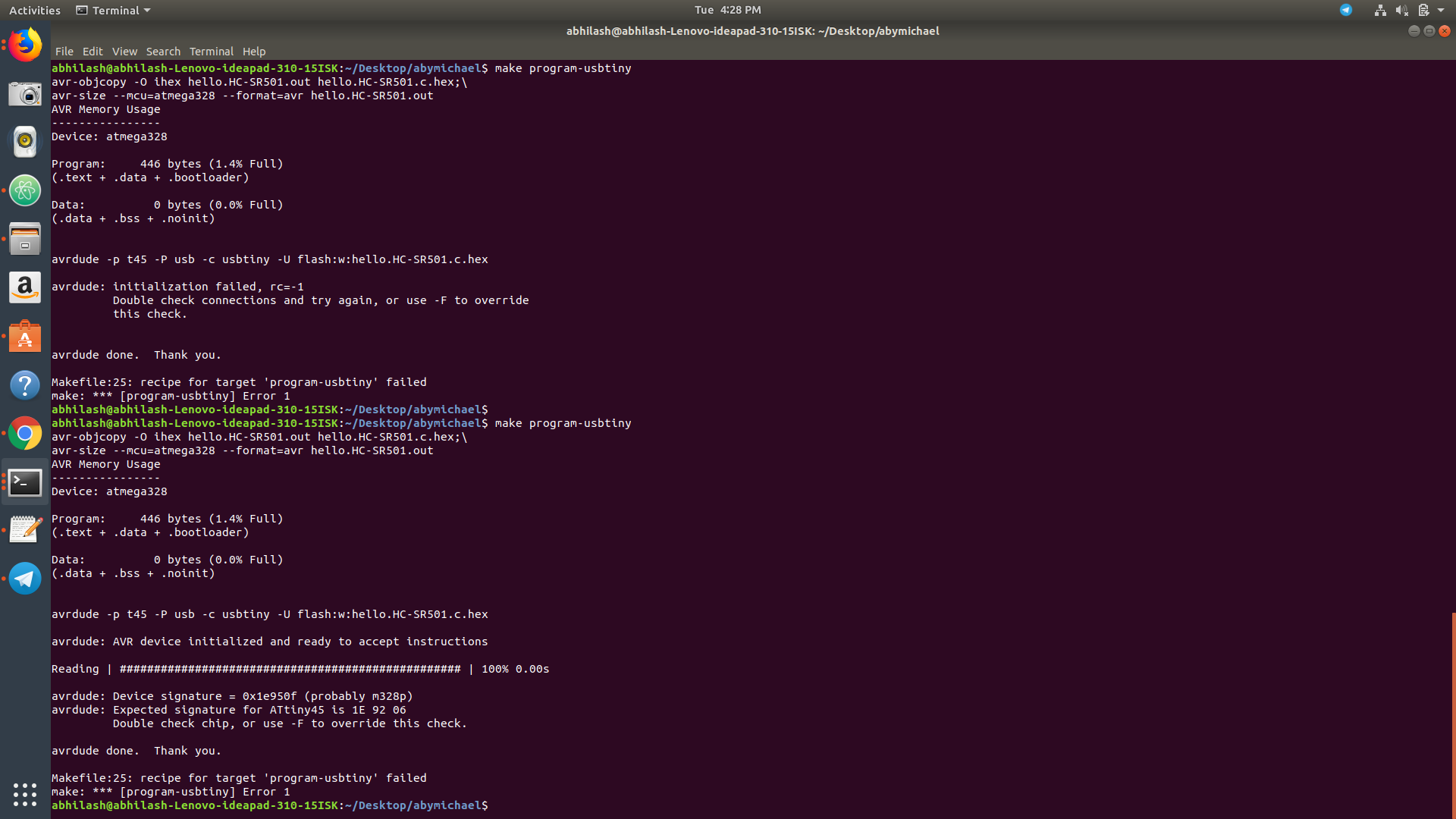
4.Flashing with make programme
Here I downloaded .c and hex file from schedule then flash it into my board for checking my board weather my board is working or not and it helped me to identify is my microcontroller is detecting , the flashing of this programme was successful so I decided to go with a programme by myself
5.Using Arduino programme
After making my board I tried to make a programme in "ARDUINO" myself ,In week assignment we want to show our input signal through any channels to show the device sensing input signals.Here I thought that to written a simple programme on arduino to show my sensing input signals. after writing a simple programme I compile and burned it into the board and is my programme
#include
#define F_CPU 20000000
#include
int main(void)
{
DDRB =0b00100;
while(1)
{
if((PINB & (1<<4)))
{
PORTB |= (1<<2);
}
else
{
PORTB &= (0<<2);
}
}
}
After the programming I decided it to connenct with a table lamp using some 'relay' connecting to my board with the help of my instructor I got some idea to connenct that sensor out put with the lamp
we can't make glow the lamp using the output volt 5v so that I used a "DPDT Relay" (double pole double throw relay).Relay is an electromagnetic device used to separate two circuits electrically and connect them magnetically. They are often used to interface an electronic circuit, which works at a low voltage to an electrical circuit which works at a high voltage. Relays are available in different configuration of operating voltages like 6V, 9V, 12V, 24V etc. the data sheet is here
So I made all the connection through soldering between sensor and lamp .Here the sensor is acting as a switch to the lamp and the relay is converting the voltage ,Here my instructor Lancy Felix gave different ideas that can operate through this connection
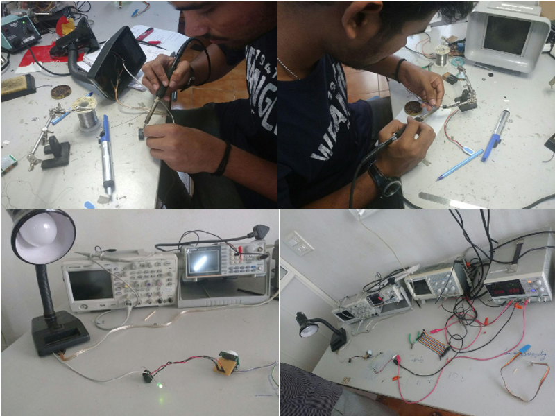
After soldering I applied voltage for the working, Here the below video is showing the working of the sensor input If there is any motion detected in the PIR sensor The voltage will regulate to the lamp and its glows after few seconds there is any motion it goes automatically of
6.Problem faced
This week taught me somany things that we are going to face normaly try to show something through a electronic circuit as a beginner,I felt somuch comfortable with milling purpose after that thing I felt difficult in programme writing and making the circuit working here I got lot of help from my instructor .In forward I want to focus on fixing these problems .At the time I use Relay to my board It wouldn't gave the output as I expected fixing of this problem was somthing difficult . So These are the stage I felt some problem and also make sure to solve it in forward