Objectives
Modifying Fabkit
I decided to modify the Fabkit , it is an Arduino-compatible board designed by David Mells and based on an ATMEGA382P microcontroller.
I got my inspiration from Lancy Felix page and MARKS C.
ATMEGA382P-AU
Data Sheet of ATmega328P-AU Click here
The main features of ATmega328p are:
Designing the Board
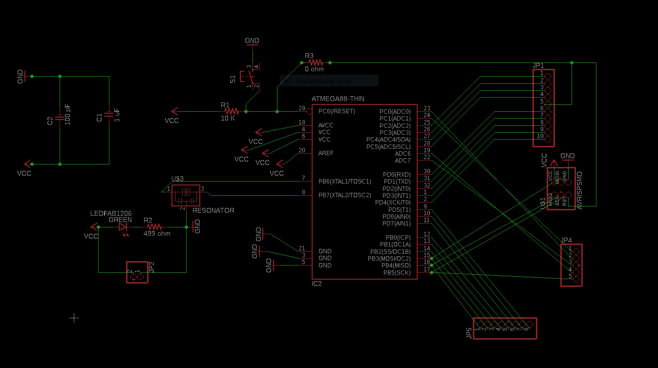
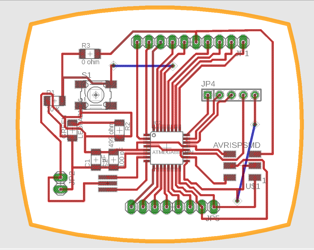
I designed my board in Eagle. As there was no ATmega 328 in Eagle library i used the IC ATmega 88thin which have the same pin configuration ( refer data sheetClick here ).
Download Eagle Schematic
Download Eagle Board
Download Board Design files
Milling and Soldering the board
I used the 1/64 tool bit for tracing the circuit path
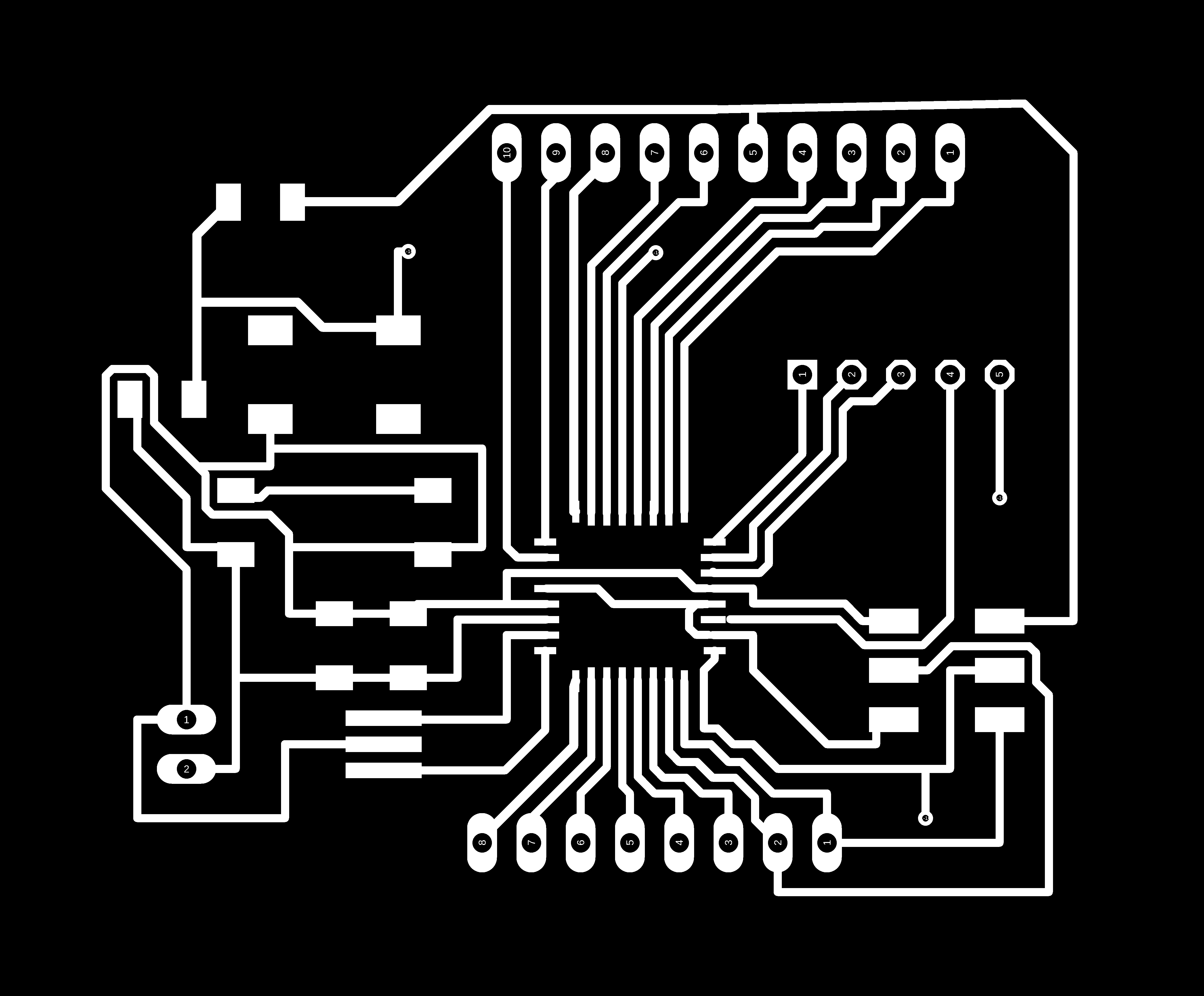
Download Trace file
I used the 1/32 tool bit for drilling the holes in the pads (for pin headers) and vias (for jumper wires).

Download Drill file
I used the 1/32 tool bit for the cuting the board out

Download Cut file
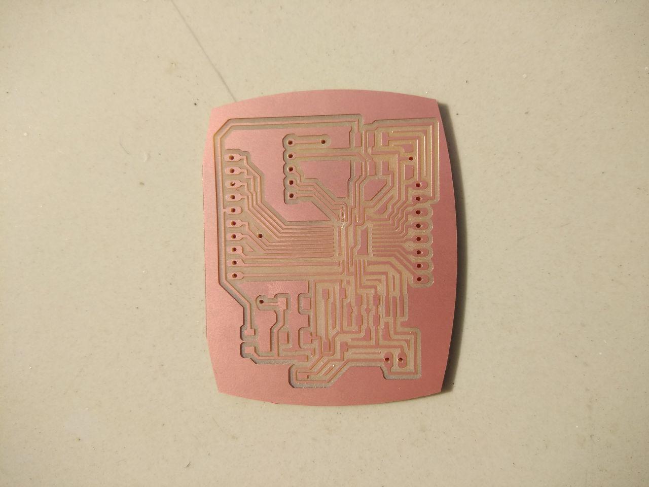
Below is a shot while milling my board
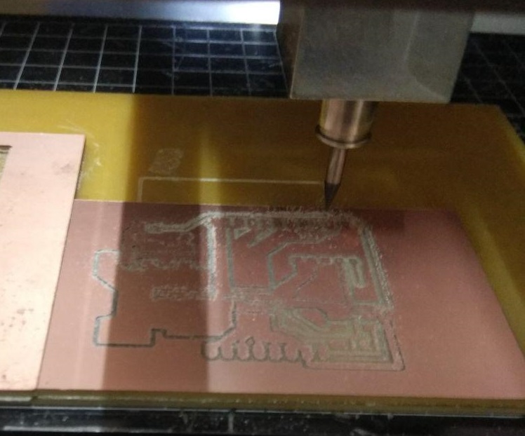
I am quiet proud with the clean and finished mill, the board looks good now, it may look ugly after i solder :D
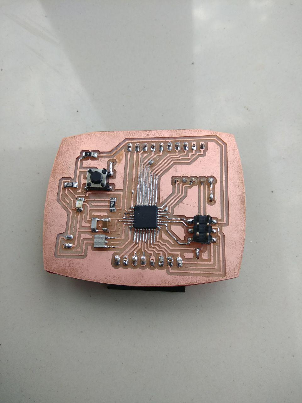
This is one isnt that bad as my previous board, i might be improving in soldering.
Back side of my board, i stick it with red vinyl sticker, and glued the jumper wires so it wont go off
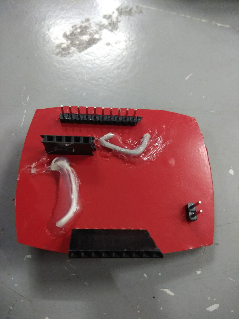
While designing, i gave all the unused Pins of Atmega328 to pin headers(1x10 male pinheaders , 1x5 and 1X8 female headers) but i forgot to include a FTDI pin header. But i could give use the jumper wires to individually take the Gnd, VCC ,TXD and RXD pins and connect the FTDI cable, see the below of this page to know how i serial communicated through FTDI cable with PIR motion sensor.
Sensors
PIR Sensor
A passive infrared sensor (PIR sensor) is an electronic sensor that measures infrared (IR) light radiating from objects in its field of view. They are most often used in PIR-based motion detectors.
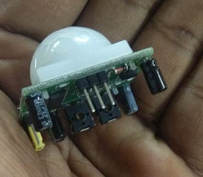
Picture of a PIR sensor
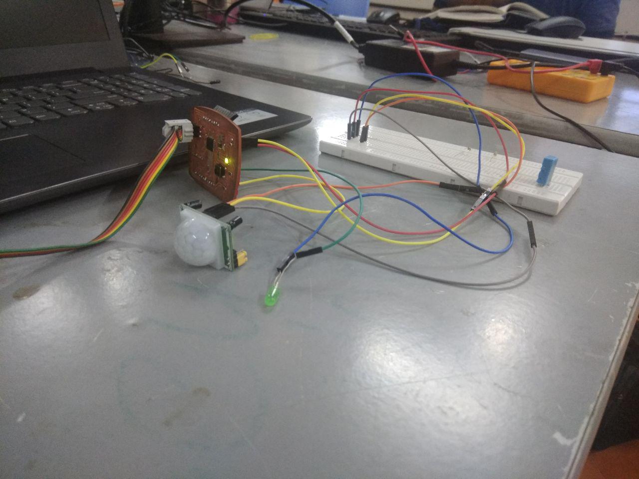
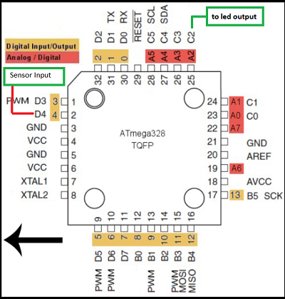
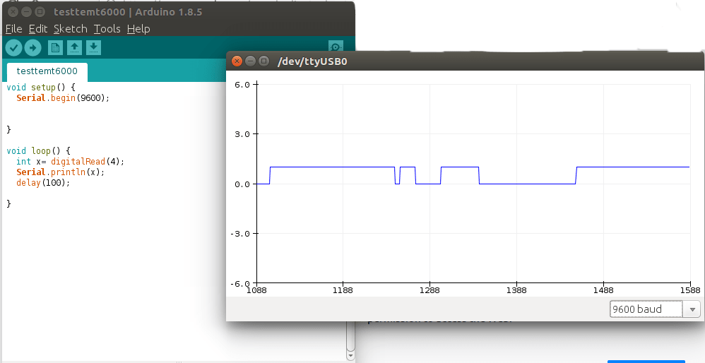
I connected the GND , VCC and output pins from PIR sensor to the GND , VCC and D4 pins of ATmega 328P-AU. Also LED was connected to the GND and the C2 pin of Atmega 328P-AU.
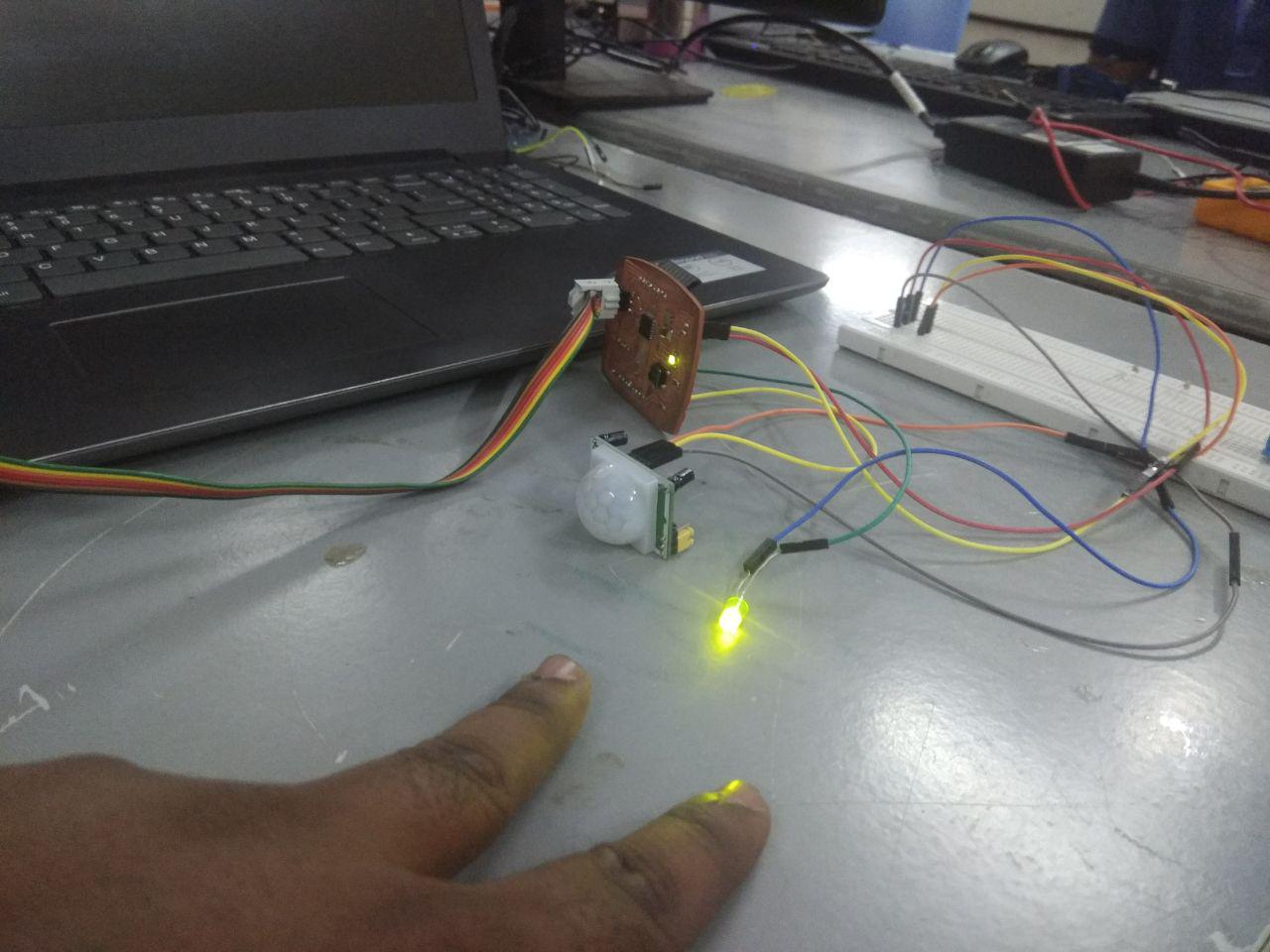
When I moved my hand the led blinked
Download Program file
Below is a video of how my program works, the Led blinks whenever a motion is detected by the PIR sensor.
I tried moving the small car molds in front of PIR sensor to make the LED blink
Group Assignment
The sensor is a module or a chip that observes the changes happening in the physical world and sends the feedback to the microcontroller. Microcontroller accepts two types of input they are digital and analog.
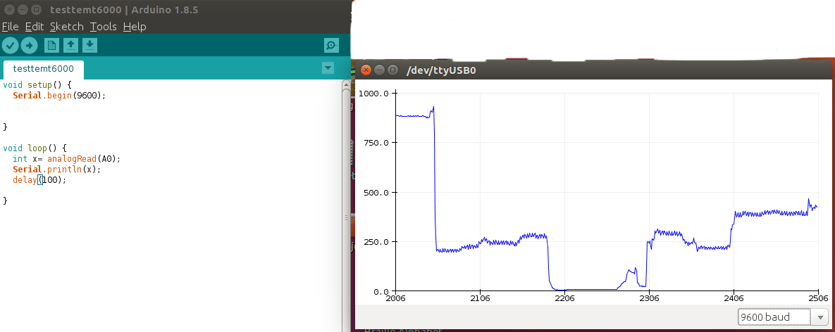
Analog sensors sensed the external parameters and given output in a range of 0 to 5V. For example if we are using LDR sensor module. In 9.00am it gives an output of 3v, and 11.am output is 4v, and 1 pm output is 4.5v, and in night output is 1v. It shows that analog sensors measure the quantity not only the presence of something.
This work by Aby Michael is licensed under a Creative Commons Attribution-NonCommercial-ShareAlike 4.0 International License.
