Making of the Braille printer
Braille printer in action
Visit Our Group Page Documentation
We have done this group project during the timeline of two weeks (May 2nd 2018 to May 17th of 2018).
First week was the Mechanical Design Week and the latter week for the Machine Design.
Week 15 - Mechanical Design
What I done?
Intro
We as a Team needed to fix on a Project Idea, so we decided to make a list of possible machines we could build
The below list were the last list of our ideas
1. Tactograph - Tactile image printer by extruding fevicol
2. Object tracking camera mount with roll, tilt and pan
3. Braille Printer/Embosser
4. Object Shooter
5. Wall printer
6. Automated drink mixer
7. Dosa Maker
After several thoughts and factors, we thought of making the Braille Printer.
Making Braille Printer was a unique idea as of its relevence and also it is relatively simple mechanism and it would be possible to make one in the limited time available.
The printer upon receiving the command from the computer prints the braille script by punching holes on a paper.
We decided to use a solenoid with a sharp end as the printing head which will pierce holes on a paper at the specific points.
The Braille printers available in the market are very costly and is not affordable to everyone. This further encouraged us to make a cheap Braille printer by making use of easily and locally available materials and also recycled materials.
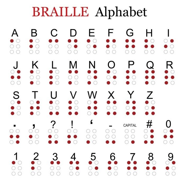
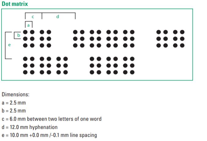
The size and distance between the dots are to be of the standard one and the measurement of the same are as below.
Tasks
I was assigned to make a chart of tasks to be done by the team, so I made this

First Prototype
After the discussions, Amith , Akhil and Rinoy made a rough idea on what all are necessary to build the X-Y axis of our printer
Purchasing some items
8mm smooth Rod for moving the head
GT2 betl(1.4mm tooth)
Driven pully and driver pully
couplers, bearings and screws
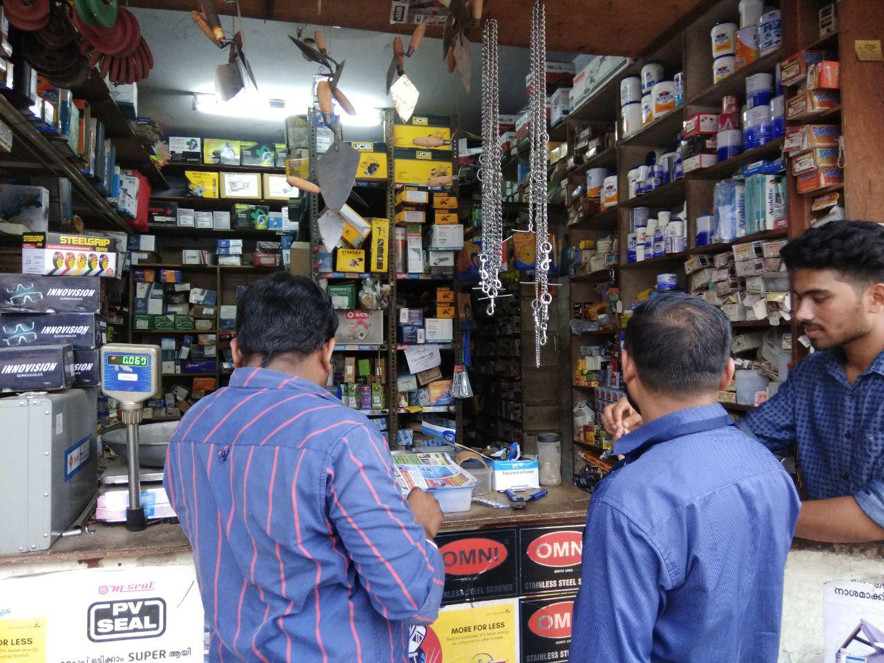
The local Shop we went for purchasing, I am the one behind camera
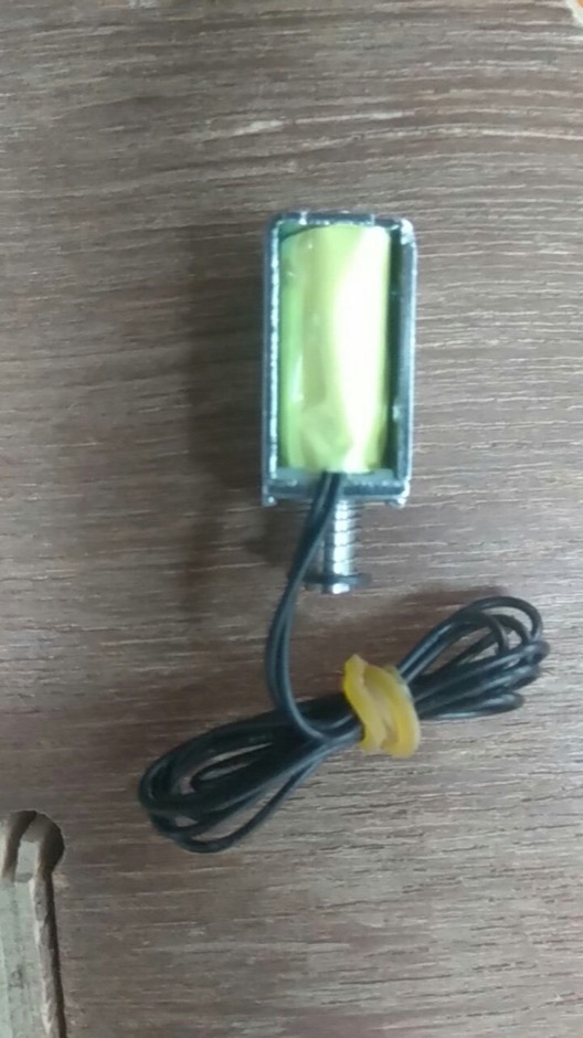
Our instructor Yadu gave the idea that of using solenoid push-pull mechanism for embosing the holes in paper.
So we ordered a solenoid form online website.
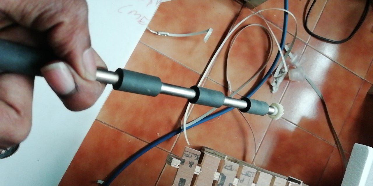
After this, along with Rinoy and Abhilash, I procured a damaged printer and opened up to get the roller with rubber bushes for the paper feed mechanisms.
Me, Amith and Vishnu was assigned with designing the basic assembly of the printer.
With a general idea, I draw a simple sketch in paper, and I designed in (Fusion360) and laser cut the side walls in an acrylic sheet and made the arrangement.
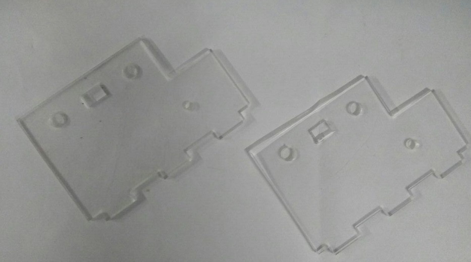
We made a first prototype of how the machine would look. I designed the acrylic rod supports and Akila designed the first version of end effector head.
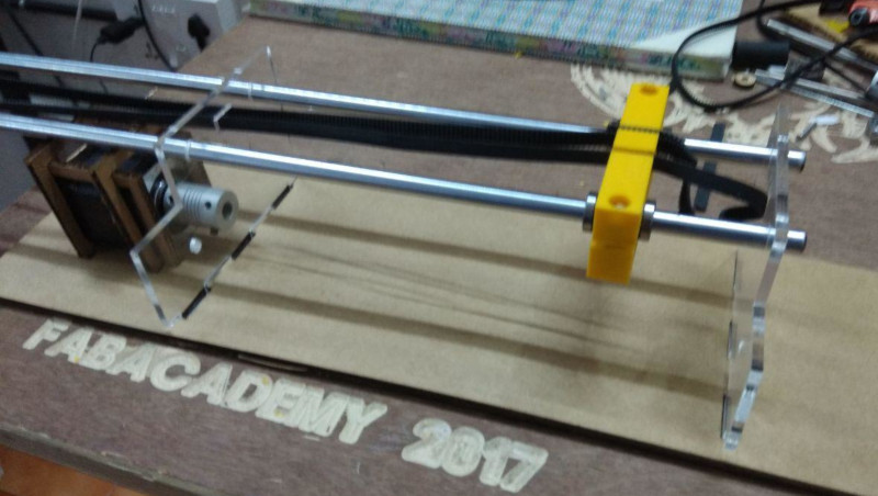
Making an assembly with rods on the acrylic sheet we understand we need a liner bearing to hold the head and horizontal arrangement of the rod to hold head is difficult to place the solenoid push-pull me along with Amith and Vishnu.
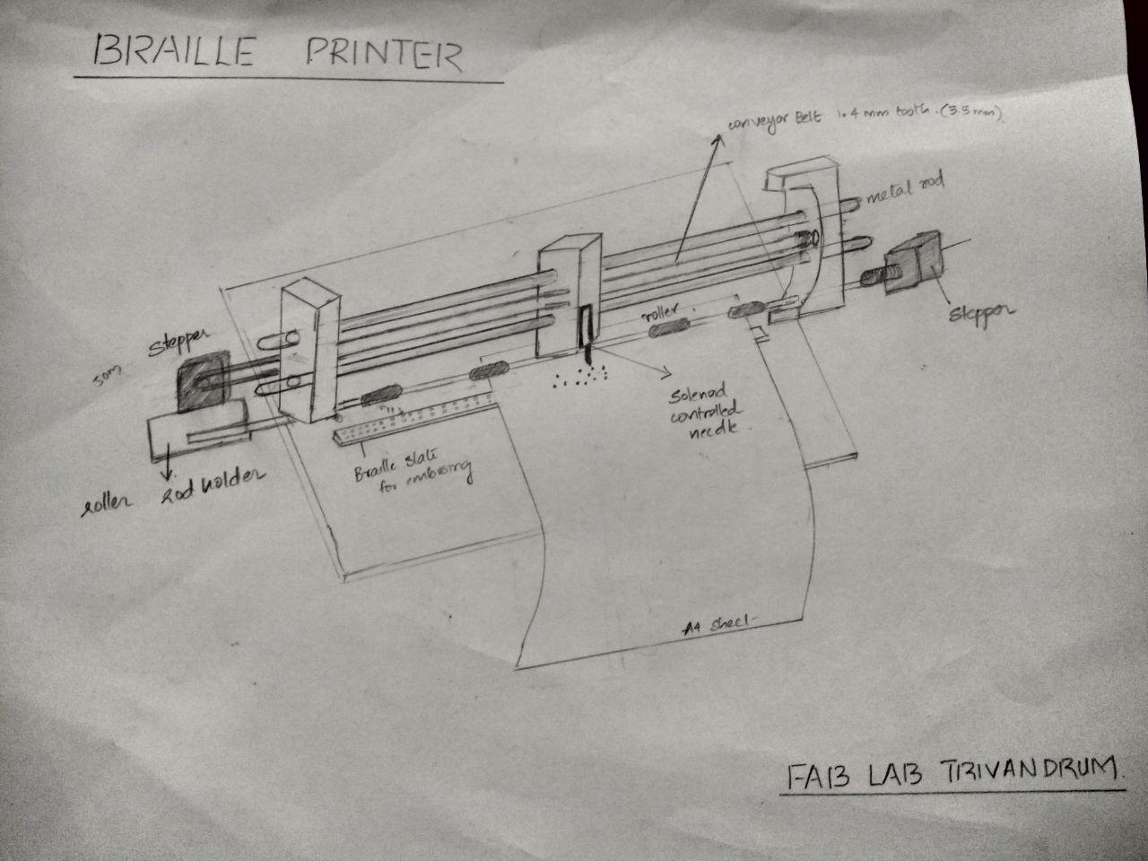
Vishnu made a good drawing of the printer on how it could be.
It is at this point me along with Amith and Vishnu started designing a support for the stepper motors.
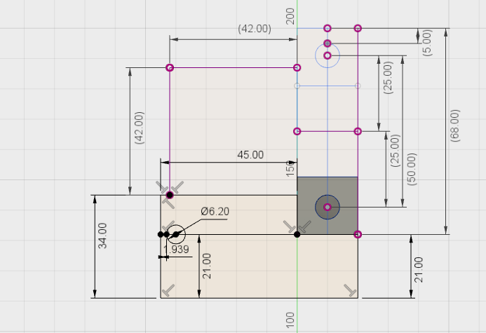
Vishnu made a small drawing in the paper, and Amith and I refer the drawing and design that in Fusion 360.
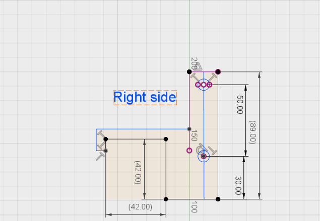
For Designing we consider the dimension of Stepper motor, here we are using Nema 14 stepper motor which dimension is 42mmx42mmx42mm.
We arrange the rod for carrying head is in a vertical position and center to center distance is 50mm. One side of the design we made a pocket to hold the roller motor stiff.
By this time we divided each tasks between us. We choosed a peculiar way in designing the components i.e., while designing a part one will assist that guy in measurements and building. This would reduce the errors and if so happened we could easily rectify it.
Sketch for Holding the Rod and Driver Motor holder
3D model of Left side along with its 3d print along with with stepper holder screwed to it
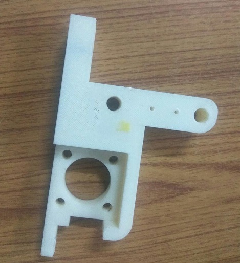
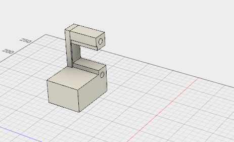
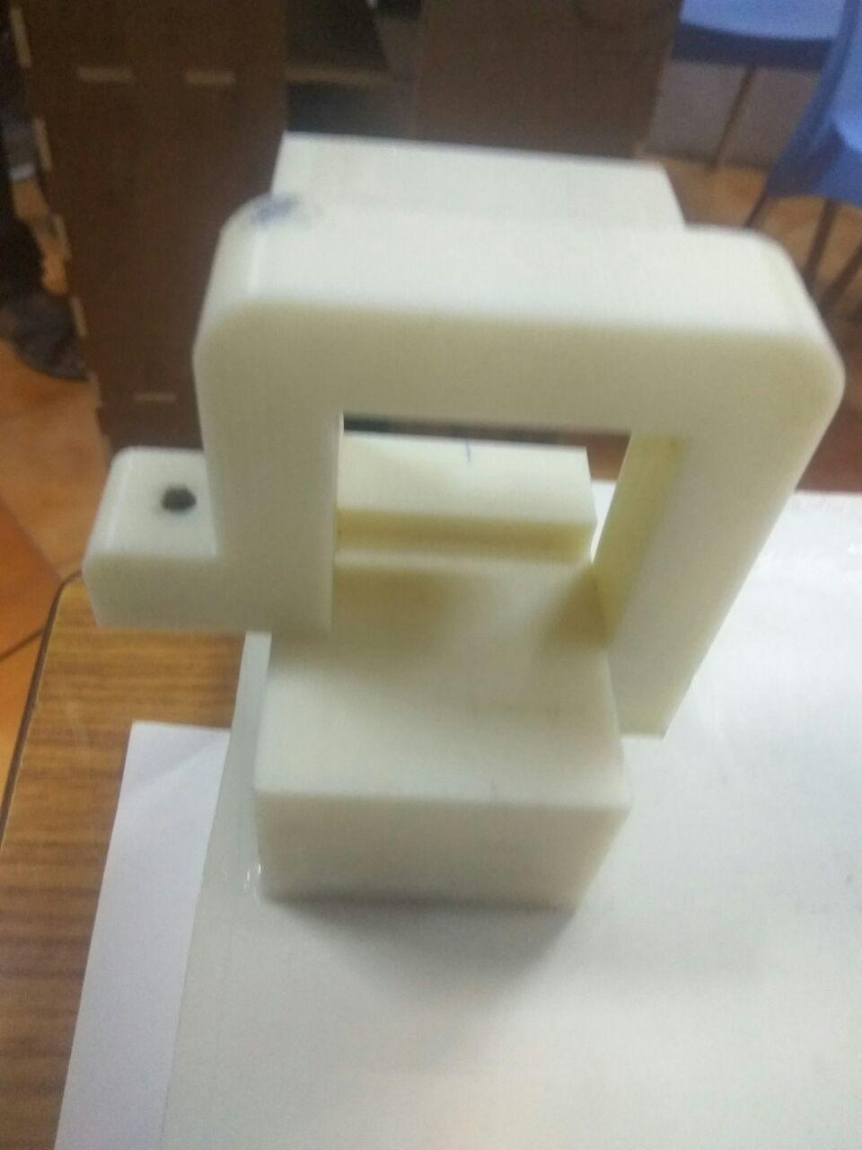
3D model of Right side along with the 3d print
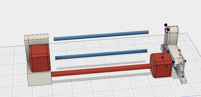
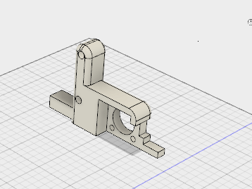
3D model of Braille Pinter
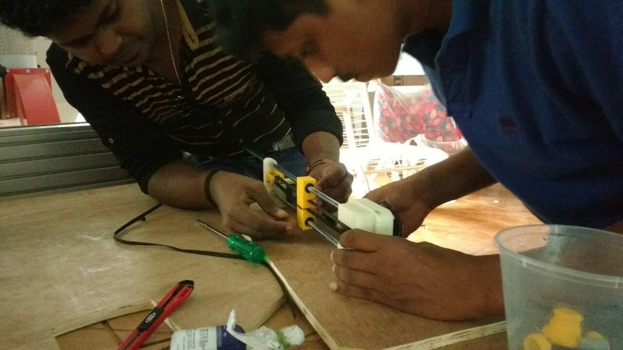
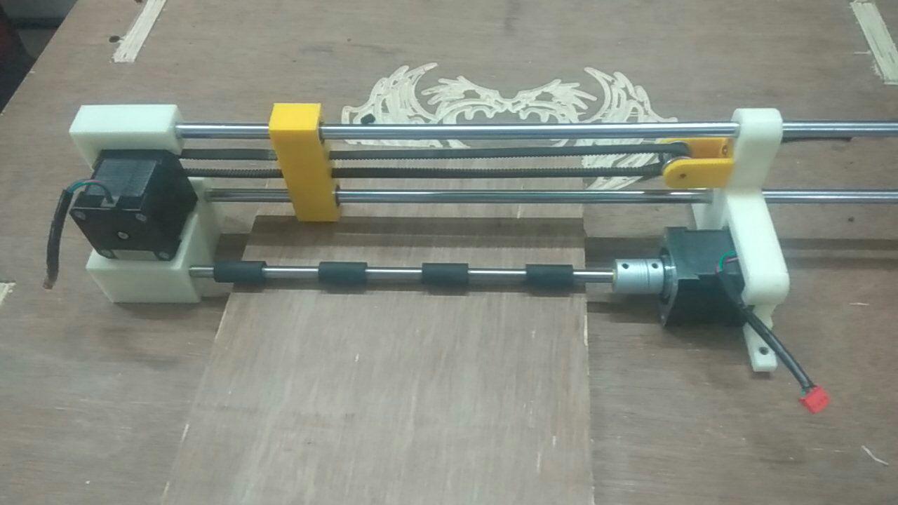
After completing the design we exported the STL files and 3D printed them in Dimension. After finishing the 3D printing(around 13 hours) we arranged it assembled them with rods and stepper motors.
After placing the motors, we connected GT2 Belt with pulley, and our assembly was now finished.
Fixing on the Tool
We started to search for alternative methods to make the end effector work.I was assisgned along with Abhilash and Akhil for this task and each of them started to work independently.
As I said earlier, our instructor Yadhu gives the idea that using solenoid push-pull we could embose holes in paper to make the dots of braille
And we bought a solenoid online
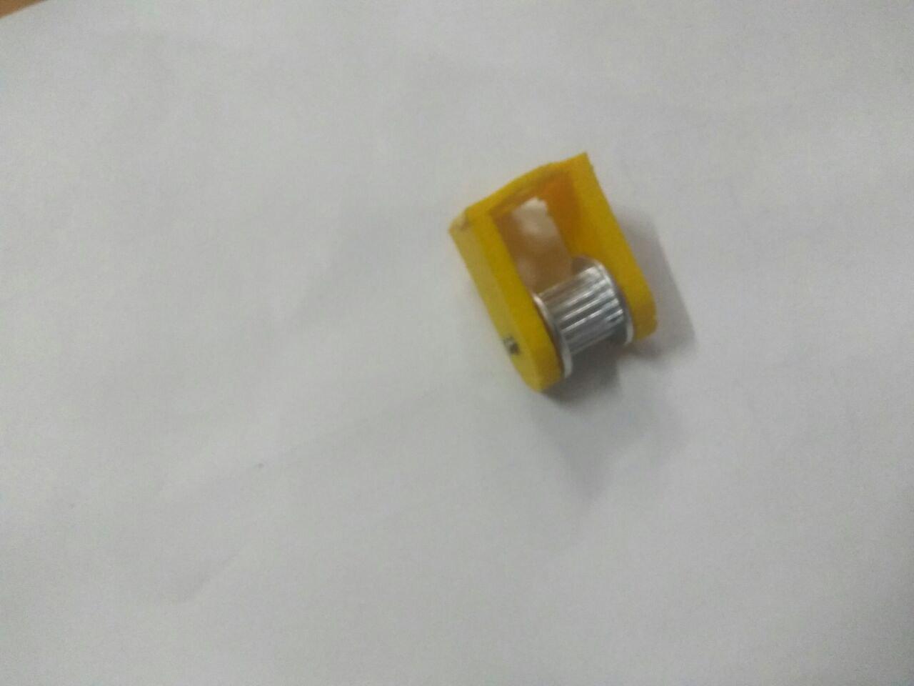
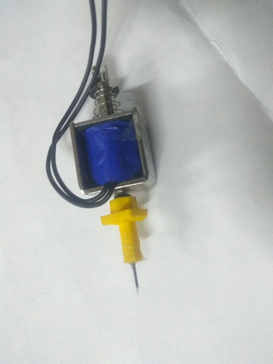
I designed small tool caps to fit in the solenoid, so we could attach a sharp needle or so.
But it proved useless as the solenoid end effector power was not good enough to embose the hole for braille
So now we have to think alternate ways, one of them was taking a servo motor for embosing and it succeeded
This made me design a mount for the servo motor
Eventhough using a servo was a viable option, yadu had procured another bigger solenoid which was delivered the day before of presentation, and the new Solenoid was the best thing.
Other Designs
We needed a limit switch. Limit switches serve as the mechanism that tells the computer the limits of the CNC machine.
When one of the axes moves to an axis limit,
the switch is activated and the machine stops.
The limit switches are also use to inform the computer of the home position.
As the axis limit was more to the right side because of the motors, I had to design a connector to keep the limit switch in position.
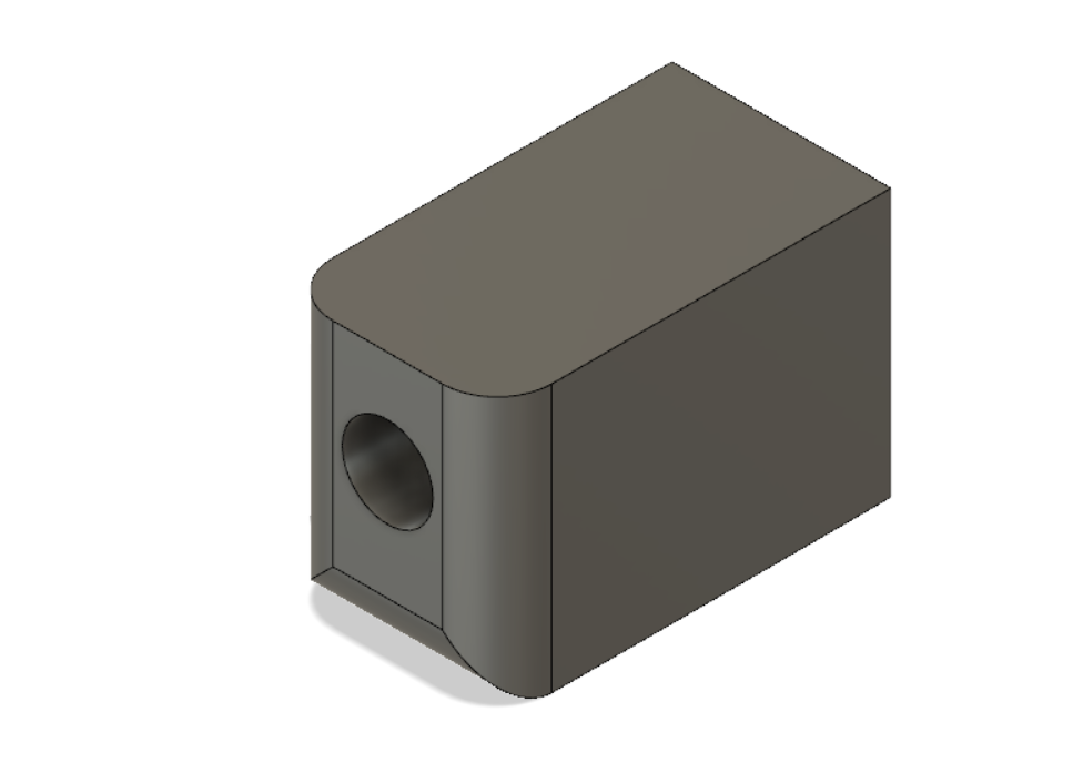
Later on I also designed a Solenoid press fit box which was never used actually , Download Design file
Download All Machine Week 1 files
This work by Aby Michael is licensed under a Creative Commons Attribution-NonCommercial-ShareAlike 4.0 International License.
