Vinyl Cutting Machine
Brief
A vinyl cutter is a type of computer-controlled machine, computer controls the movement of a sharp tool like a knife. This tool is used to cut out shapes and letters from sheets of thin self-adhesive plastic like material which is vinyl. A vector based design is created in a any CAD software and sent to the cutter via the printing software Fab Module giving all the presettings like force, velocity, cutting offset and pixel errors, where it cuts along the vector paths laid out in the design. The cutter is capable of moving the tool on an X and Y axis over the material, cutting it into any shape what so ever.
Steps to cut on Vinyl Cutter.
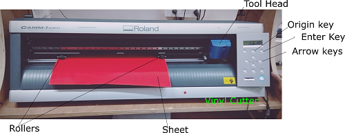
- First release the lock of the pressure plate , there is a handle on the left back of the cutting plate and pushing it down releases the lock.
- Then we should load the roll or slice(piece) of vinyl sheet from the back.There are white coloured shades on certain places on the cutter plate, we should only place the rollers between these whites. White shades have these pressure sensor which help to calculate the x-axis or width of the sheet and they have these grips which could hold the sheet stable during the cut.
- The manual control buttons are on the right side of the machine.when the switch is on, we should set the sheet to roll or slice. Switching on would make the machine tool head to a default origin position which is near to the left roller. And after loading the sheet, push the lock upward and the tool head circulates between rollers and calculate the x and y axis length you could change the origin of cut manually by the arrow keys and drive to any desired x and y position of the sheet.
- Now our machine only requires cutting parameters and the design file to make the cut.
Designing the vector image on Inkscape and use of the FAB Module
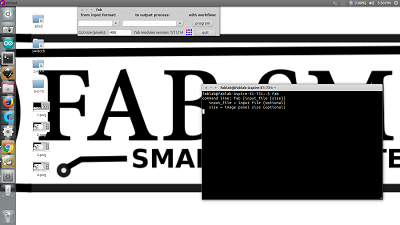
Vinyl cutters can only cut shapes from solid colours of vinyl, a design with multiple colours must have each colour cut separately and then layered on top of each other. And since the shapes are cut out of solid colours, photographs and gradients cannot be reproduced with a stand alone cutter. So raster files cannot be cut and low resolutioned vector images are very hard to cutin the machine. I have used the Inkscape software for tracing the bitmap of raster images to generate a vector file of the shapes that i intend to cut, and then send the file to Fab module. Fab Module is a printing software for vinyl cutter, it converts the vector file to a path file. This path file can be converted to .camm file and setting the cut would make the machine to cut the path generated by Fabmodule on the vector file.
Setting the Fab Module
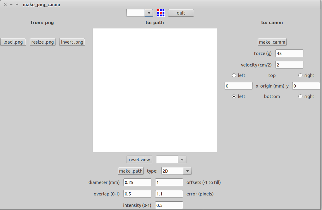
- The png vector image is opened on the Fab module and we could resize the image to the desired dimensions
- And then we click the make .path and the FabModule creates a the cutting path of the image.
- There are multiple options to view the path images , for eg segments , path view,etc
- Below the make .path option there are certain parameters which decide the quality of our cut, we should provide the right parameters for getting the right cut.
- The error pixels is one such parameter, for normal cuts with simple shapes error pixels can be 1.1 to 1.5, but for intricate cuts we should decrease the error pixels.
- Offset is normally given 1 , it is the number of times the tool goes through the path, ie if offset is 2 the tool cuts the same path twice.
- Now the force and velocity, there will always be a default force and velocity assigned to the machine, but we could manually set the force and velocity on fabmodule. Simple and plane paths could be cut with relatively medium force around 90 and velocity of 5. When it comes to intricate designs, as there are very small segments in the path, high force around 110 or 120 and very low velocity 1 or 2 is required.
- When all the parameters are set, we could make the .camm file and click on the cut.
My Vinyl Cuts

Being a fan of Real Madrid Football Club , i decided to design the Real Madrid Club Logo for my first vinyl cut and it was quiet good
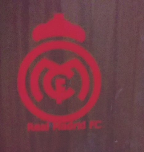
I stick the Real Madrid logo on my room door

Fab Lab logo

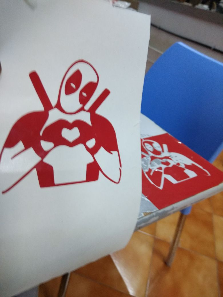
Deadpool Image and Vinyl Cut
Download Design Files Design files
Laser Cutting Machine
Brief
Laser Cutting is the computer-controlled cutting technology using laser. A laser cutter can cut any intricate parts with much ease and very good surface finish. Other than cutting the materials, laser cutter is also used for engraving on surface of materials, engraving is a beautiful art and we could literally make an art out of engraving.

Laser Cutter

Laser head and Bed Controls of the machine

Laser Tool Head
Safety and Precautions
- The most basic lessons in dealing with a laser cutter is being aware of the safety and precaution while dealing with it.
- The Laser Cutter we have here is CO2 laser cutter, which means CO2 gas is used as the laser and the by products of cutting are very harmful gases.
And to collect these gases there is a parallel air filter attached and we should switch on the filter whenever we are cutting. - As the laser cutter emits very high laser beam, fire can happen during the laser Cutting due to over focussing,
incase of a fire you could stop the laser and open the lid to exhaust the fire.
If the fire still not stops you could use an extinguisher or a blanket to cut out the oxygen - A Laser Cutter is a costly machine and each parts of the machine could cost you a bit, so replacing them can be a task, giving jobs that could overload the laser at high frequency and velocity could damage the machine.
Group Project
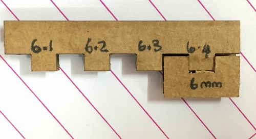
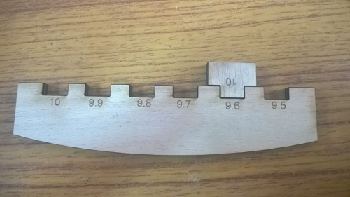
Several combs were cut for finding the kerf. Kerf is the width of the cut burned by the laser. The cardboard was first cut and the kerf was 0.2mm
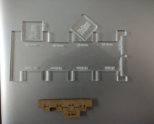
Acrylic was cut then and the kerf was 0.3mm
Wood was later cut and the kerf was 0.3mm
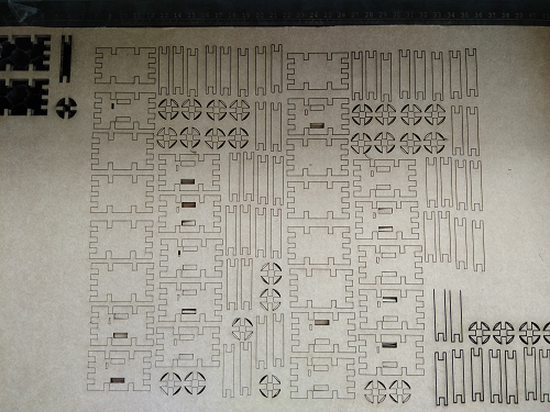
Individual Assignment - Parametric Design Cutting
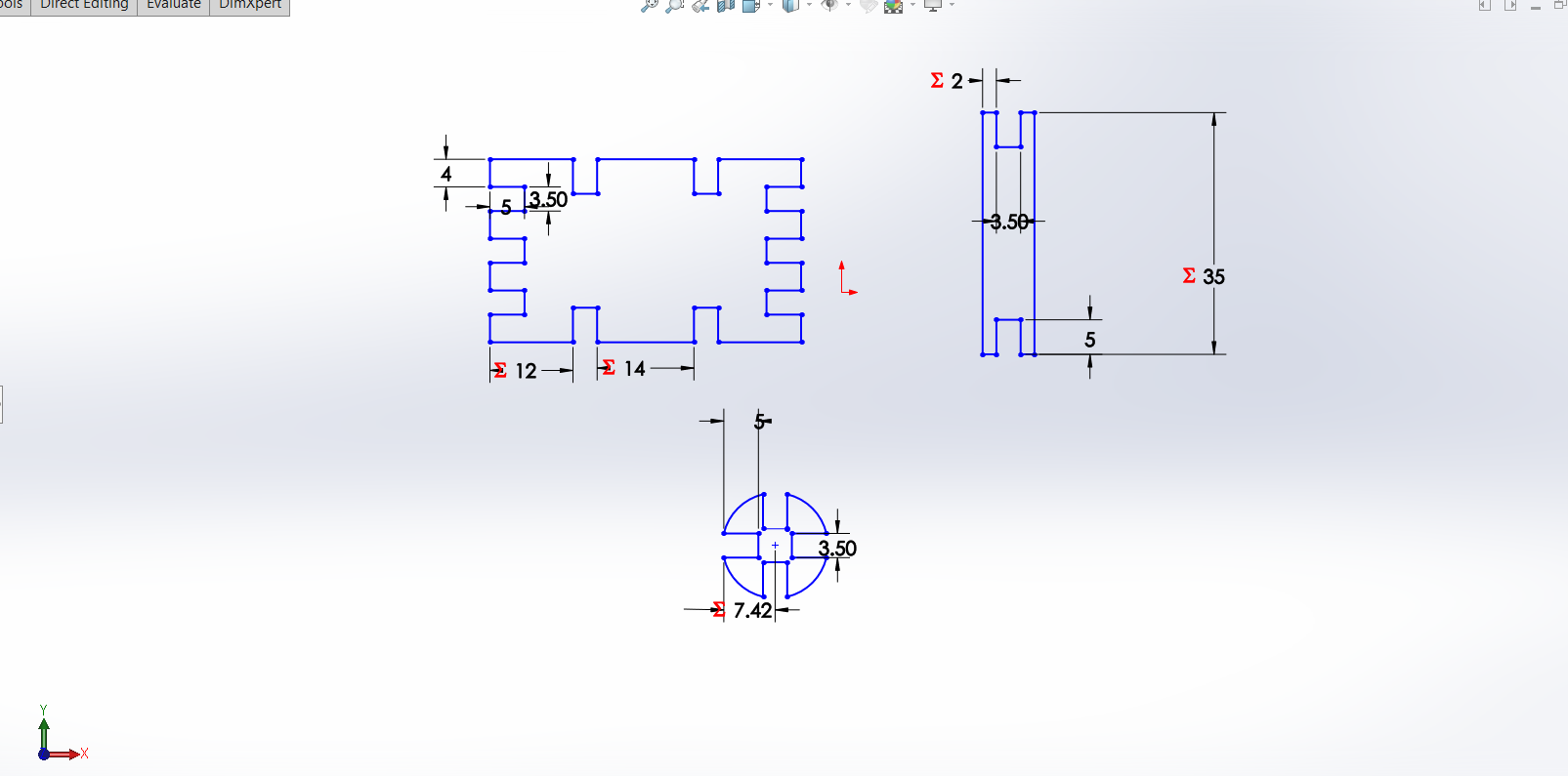
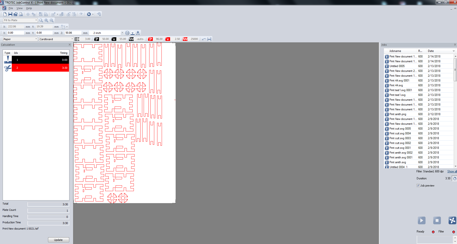
I decided to make some humoid cardboard players
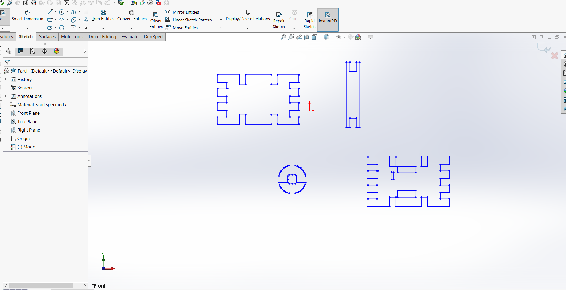
So I draw 2D sketches of some shapes in Solidworks through parametric designing
Download Design Files Humanoid Cardboard Players ParametricDesign file
Parametric Designing
In Solidworks, we have to create some global variables which will be defined to be the basic dimensions of our design.
We can select the Equations option from the Tools toolbar.
In Equations Tab there are three options
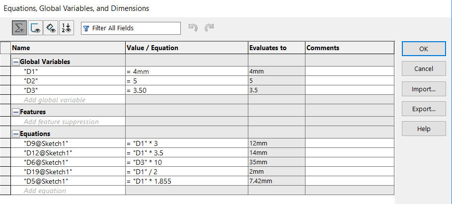
I gave three Global variables D1, D2, and D3, and made equations of other sketch in relation to any of them.
In the Global Variable section, click an empty cell in the Name column.
Enter a name for the global variable.
The SOLIDWORKS software does the following, it Encloses the name in quotation marks,
Moves the cursor to the Value/Equations column and inserts = (equal sign) and
Displays a flyout menu with options for starting the global variable.
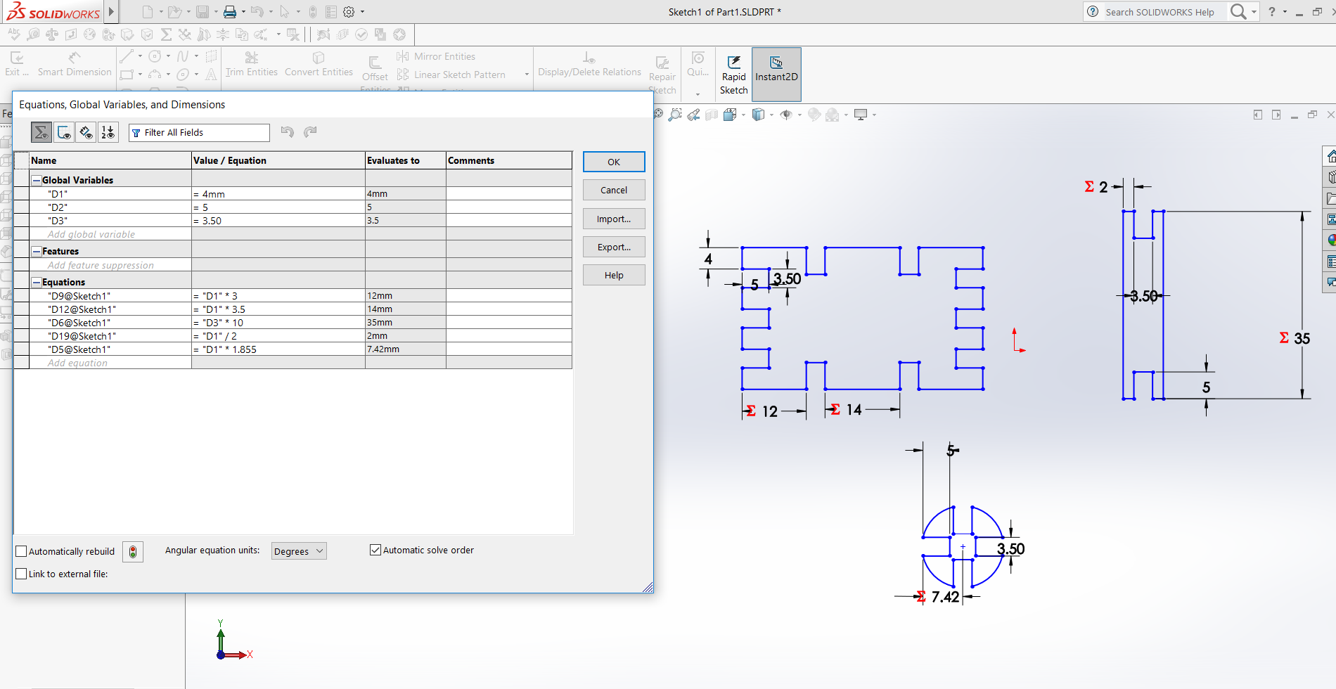
After = (equal sign), add a term or a dimension to the global variable by clicking a dimension in the graphics area.
SOLIDWORKS makes the dimension name in the cell.
Now measure and give the required basic dimension with the given name.
We can also add comments to each dimension.
In Equations, we can define and build relations between different dimensions and design conditions with our Global variables.
Also we could give conditional statements
The following variables can be used for creating equations
Dimension names
Global variables
Other equations
Mathematical functions
File properties
Dimension measurements
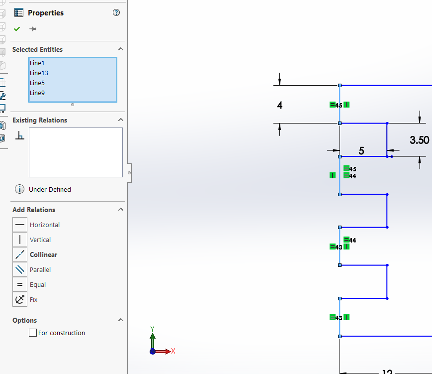
In Solidworks we could give basic relations between points, lines, circles, angles etc just by clicking them.
For example, I have selected all the dimensionaly equal lines and selected them using shift key.
This opens up a Properties Tab on the Left side, where we have options to define relations such as vertical, horizontal, equal , parallel, colinear etc.
Setting the laser cutter and use of Inscape
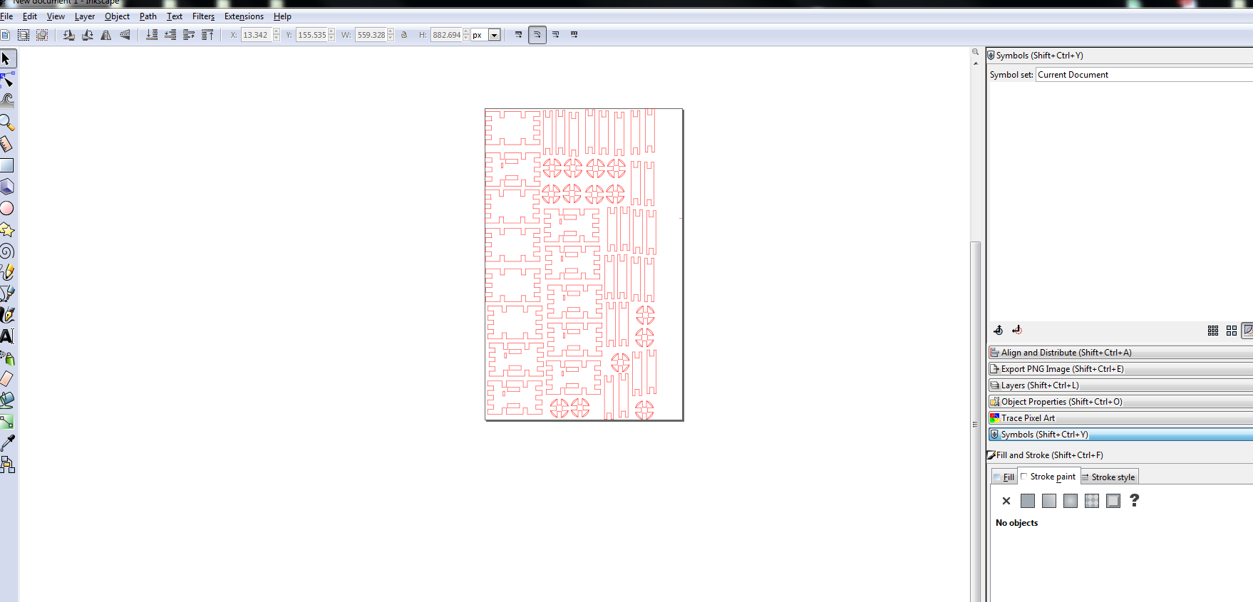
Upload the design files to Inkscape and we should note that the font style should be set to RED for cutting and BLACK for engraving as per our Laser Cutter, but we could change the colours as we want.
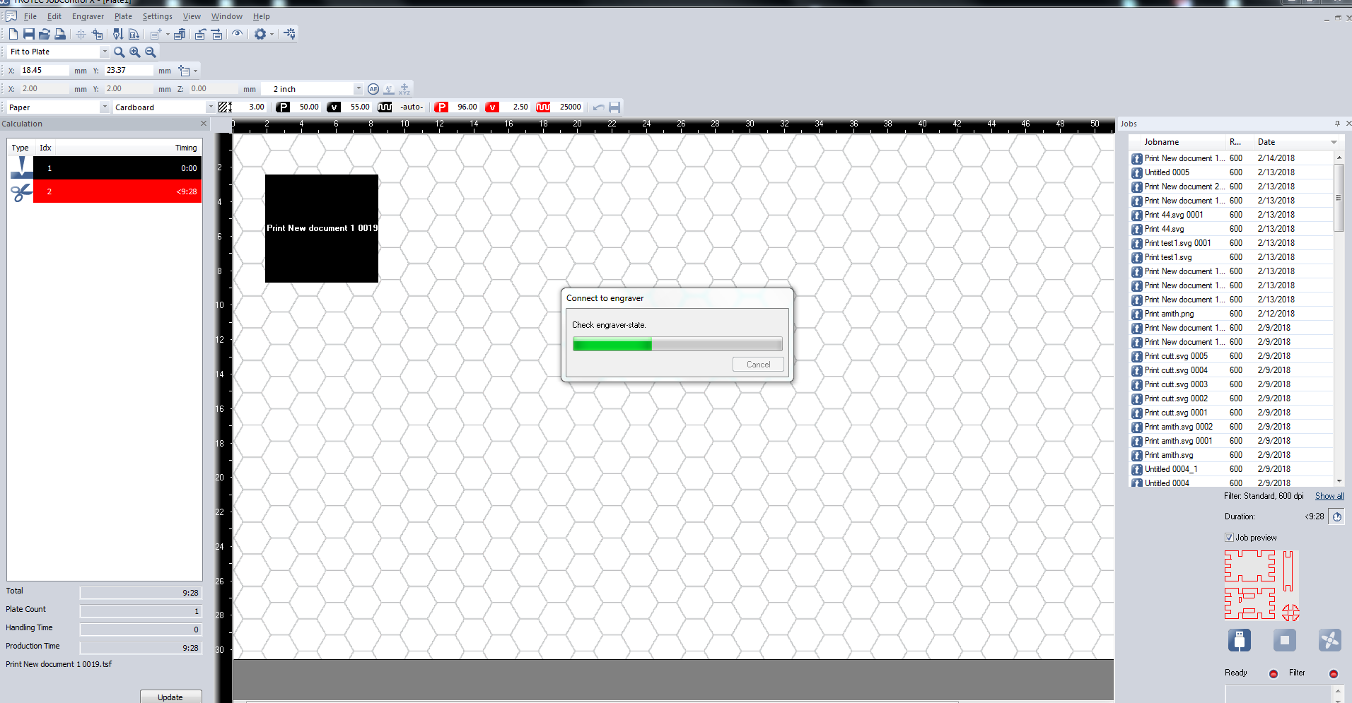
Then set the width and height of the print and press Ctrl-P, it will then automatically opens the Trotec Laser cutter page. Set the material type for both cut and engrave and press the connect key and press print
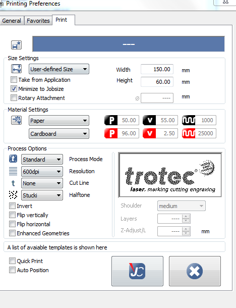
When clicking the print key, it automatically opens the Laser cutter printing software as below, select your job from the list on the right side and press ready key to connect to the Laser cutter
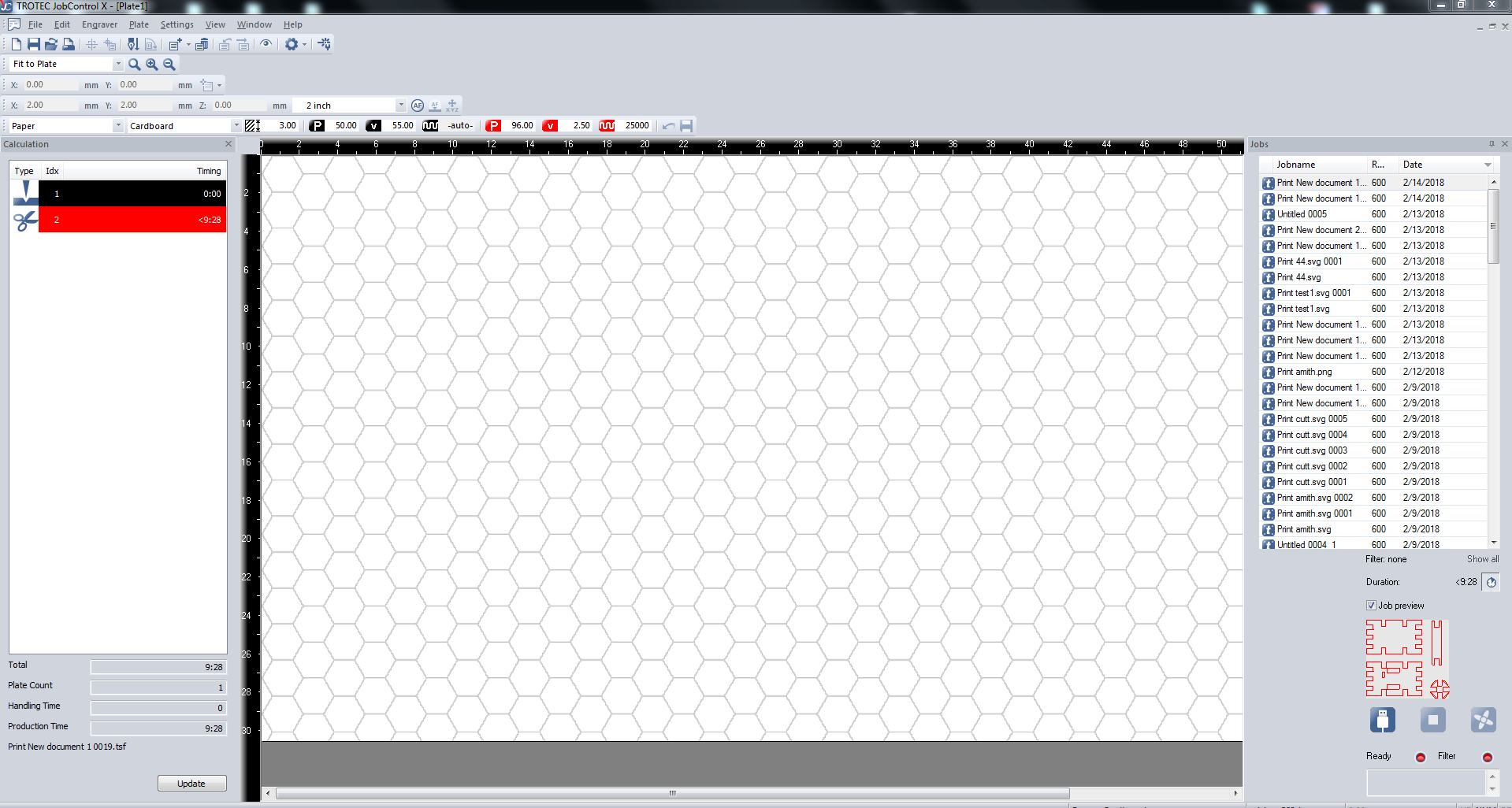
Before we click on the ready key, we should switch on the cutter and airfilter,
set the bed and focus the laser point , then select the job and click on ready to cut, then the cut will begin
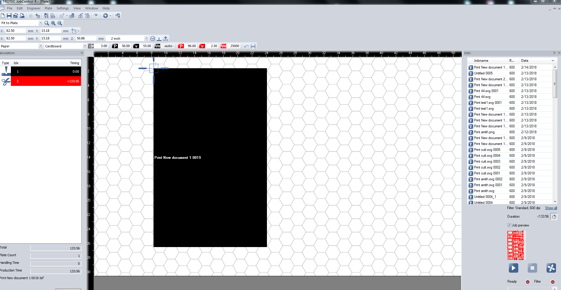
Put the Engraver on the desired X-Y origin and click ready for starting the cut
After the laser cut
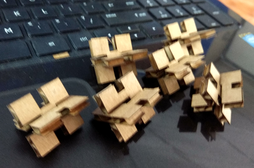
First I made some cardboard legos
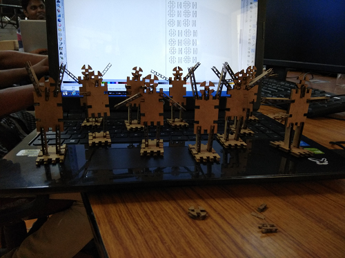
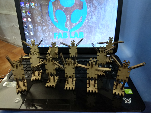
Then I arranged them as a Humanoid Army
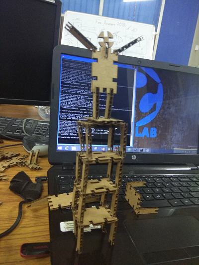
The one Humanoid Soldier on top
Download Design Files Humanoid Cardboard Players ParametricDesign file
This work by Aby Michael is licensed under a Creative Commons Attribution-NonCommercial-ShareAlike 4.0 International License.
