Objectives
Basic Electronics and Components
Current (I) is a flow of electricity which results from the ordered directional movement of electrically charged particles.
Voltage (V), also called electromotive force, is a quantitative expression of the potential difference in charge between two points in an electrical field. It can be direct or alternating.
Resistance is an electrical quantity that measures how the device or material reduces the electric current flow through it. The resistance is measured in units of ohms (Ω). If we make an analogy to water flow in pipes, the resistance is bigger when the pipe is thinner, so the water flow is decreased.
One volt will drive one coulomb (6.24 x 10¹⁸) charge carriers, such as electrons, through a resistance of one ohm in one second.
Electronic Components
Active and Passive components
Active electronic components are those that can control the flow of electricity, and they work according to the functions given to it. Some examples of active electronic components are transistors, vacuum tubes, silicon-controlled rectifiers.
Passive electronic components are those that dont have the ability to control current by means of another electrical signal and they are only capable of doing specific function . Examples of passive electronic components are capacitors, resistors, inductors.
Through hole components and Surface Mounted Devices
Through hole components are those components manufactured in such a way that the stuffing to the board is done through a hole in the board
Surface Mounted Devices or SMDs are those components that can be surface mounted to the board and soldered.
In our FabLab we use SMD components
DIODE
A semiconductor device with two terminals, allowing the flow of current in one direction only. The two terminals are cathode and anode with the cathode end of the diode may have a line marked .
Resistor
A resistor is a passive two-terminal electrical component that implements electrical resistance as a circuit element.
Capacitor
A device used to store an electric charge, consisting of one or more pairs of conductors separated by an insulator.
Pull-up and Pull-up resistor
Pull-up resistors are resistors which are used to ensure that a wire is pulled to a high logical level in the absence of an input signal. Pull-down resistors work in the same manner as pull-up resistors, except that they pull the pin to a logical low value
Resonator - crystal oscillator
A crystal oscillator is an electronic oscillator circuit that uses the mechanical resonance of a vibrating crystal of piezoelectric material to create an electrical signal with a precise frequency. When connected in an electronic oscillator circuit, resonant mechanical vibrations in the device generate an oscillating signal of a specific frequency
Microcontroller
Microcontroller is a small computer on a single integrated circuit. It has only a CPU inside them in one or few Integrated Circuits.
PCB Designing
EAGLE (Easily Applicable Graphical Layout Editor)

Autodesk EAGLEis a design software for designing schematic circuit diagrams and also the PCB .
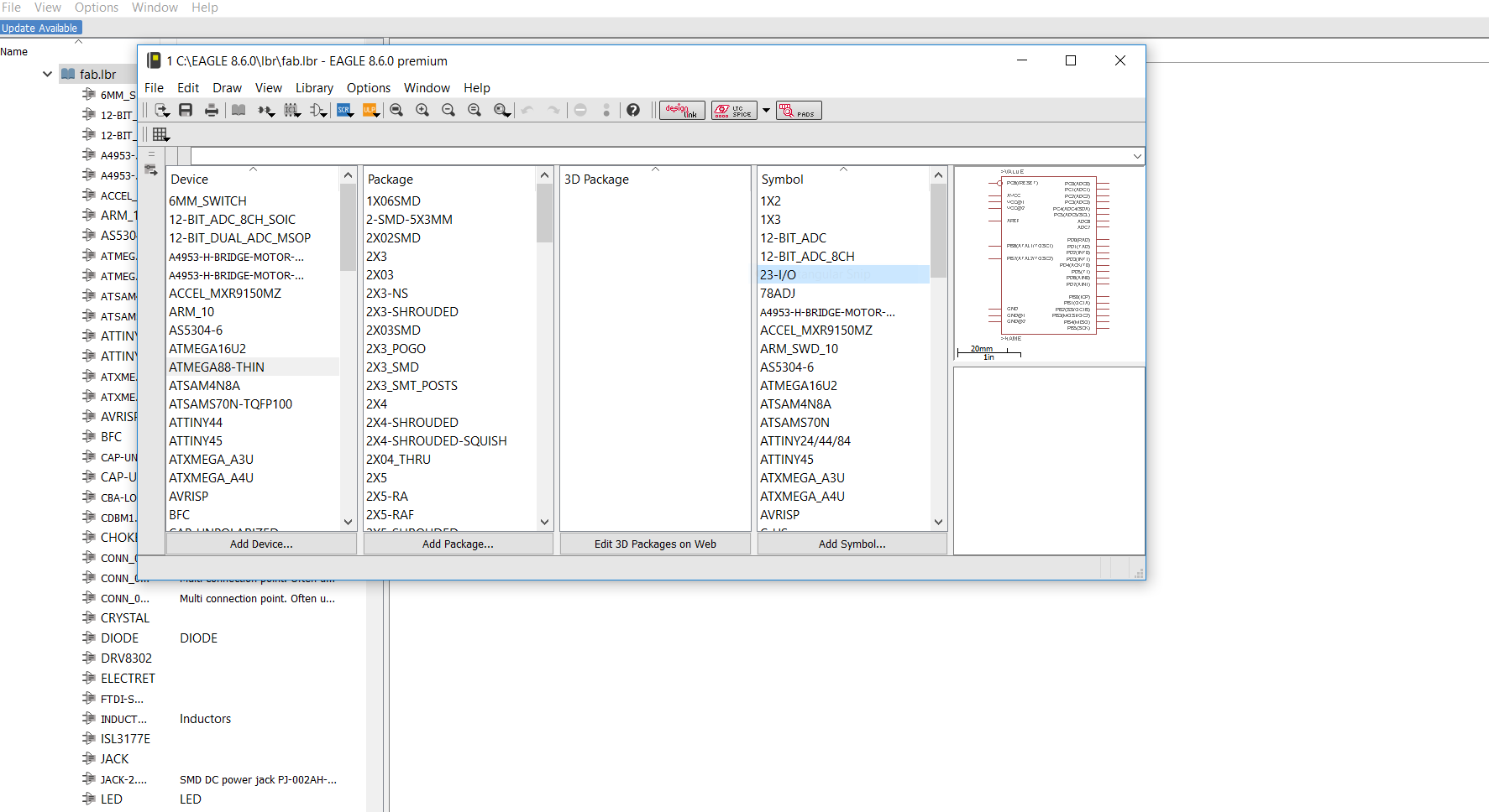
Once installed EAGLE you will need to add the Fab library to the Eagle, Fab Library is the whole list of components we use to build PCBs with the FAB standard dimensions and names.
Steps in Design
Basic designs
I tried a simple design with a LED, Switch, Resistor, and a Pinheader.
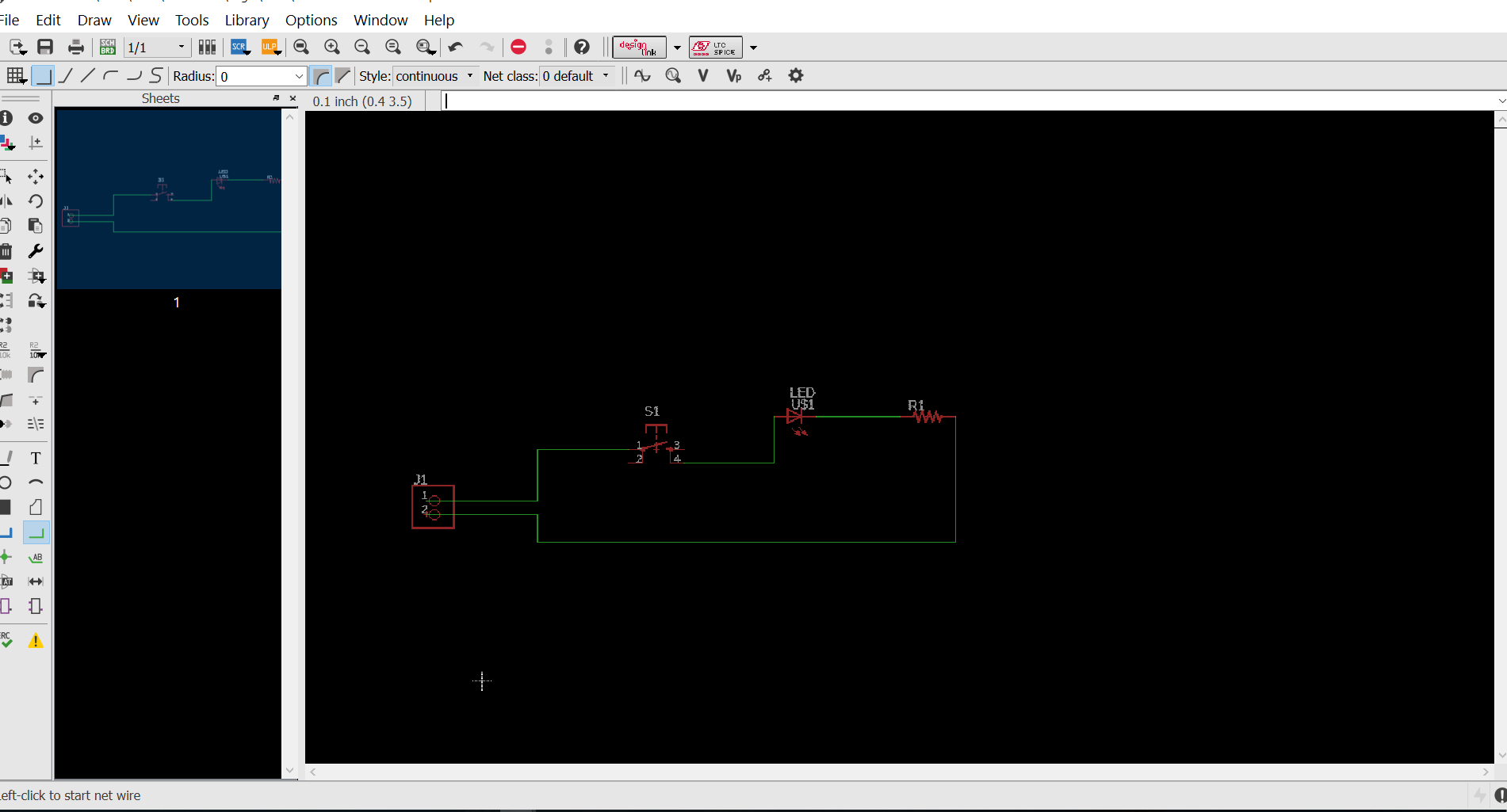
Schematic diagram
There are certain commands we can use in EAGLE. Add command can open the library and we could add any components available to the create the diagram.
Then Move command to move items, Delete command to delete items.
Net command to create wire connections.
Root command used for creating the connection between the components manually
Rotate command to rotate the oreintation of items.
We have a tool box on the left side which have all the above command tools and also other tools like copy, paste, groups, select , layers etc.
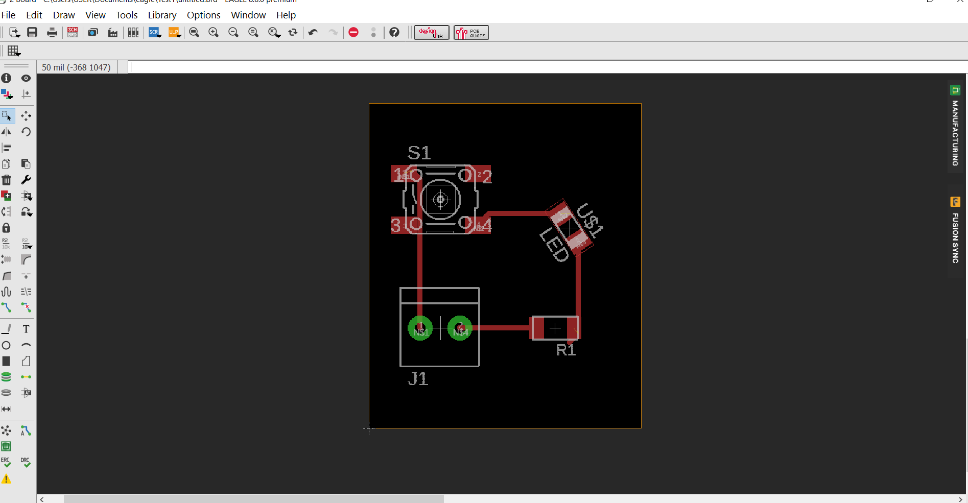
Board Diagram
In schematic diagram go to Files tab and click Switch to Board we get components spread with connections, we just have to assemble the components to get a good board diagram
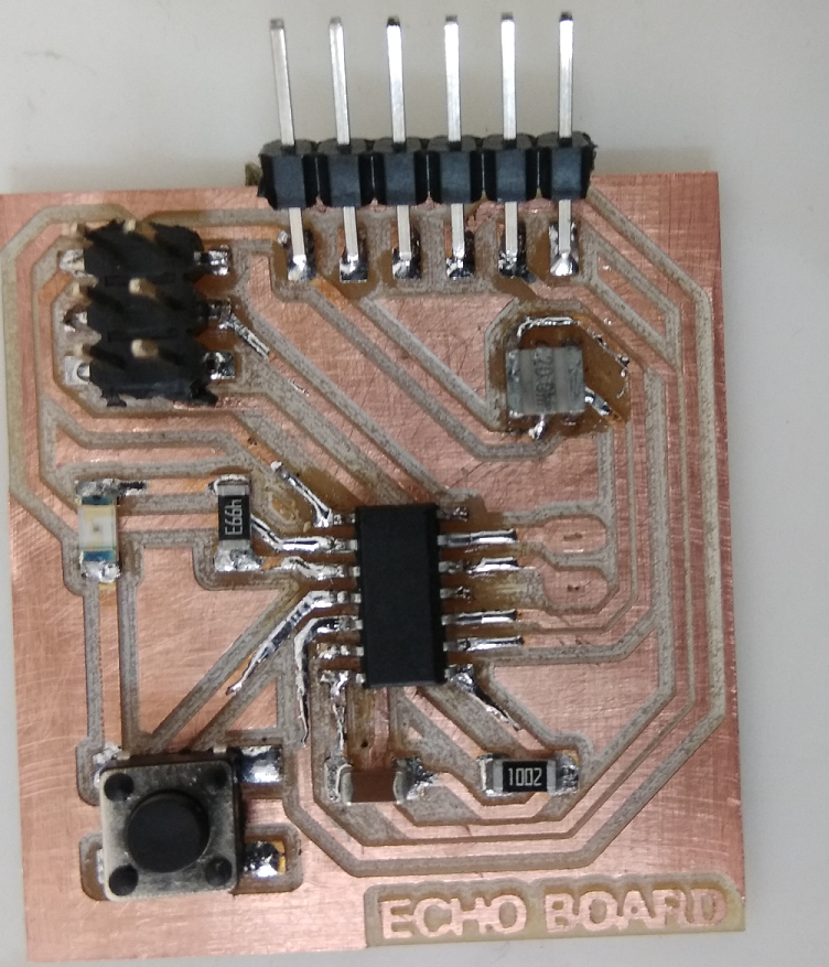
HelloWorld ECHO Board
We will be using the schematic of the Hello Echo Board, and our task is to redraw this schematic to include an LED, a switch and a resistor.
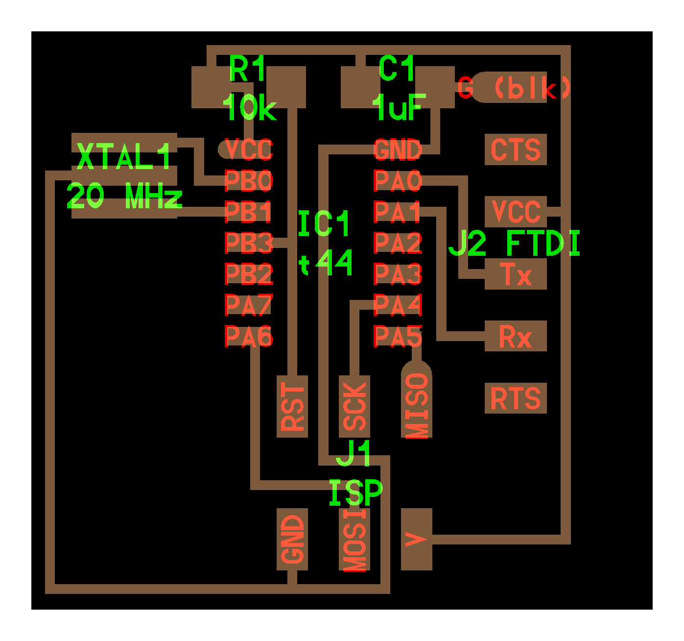
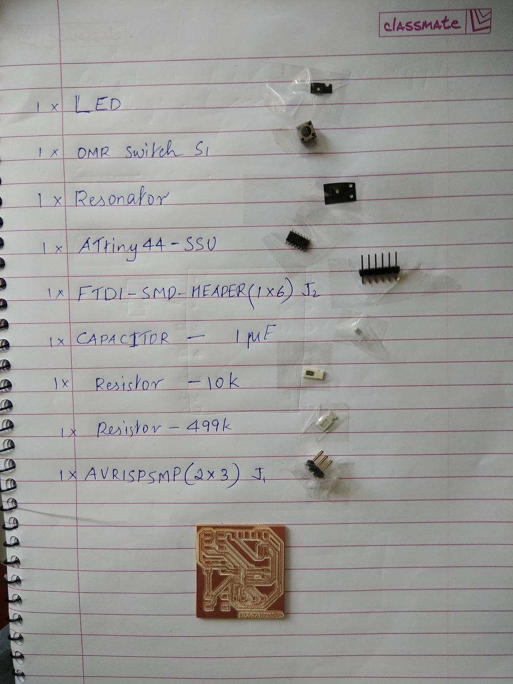
Components Required
- ATtiny44-SSU: Datasheet
- 20mhz resonator: ATtiny has an inbuilt 8mhz clock, but this one makes it faster and more accurate.
- 6mm Omron Switch
- AVR ISP SMD header 2x3 : for programming the board
- FTDI SMD header 1x6: powers the board and allows it to speak to the computer
- A 499ohm resistor for the LED and a 10k resistor for the switch
- 1µF capacitor
- GND: Ground
- VCC: Power supply
Drawing the Schematic Diagram
Add the components and draw the circuit. Use add, move, rotate commands as necessary and also use net command to make connection wires
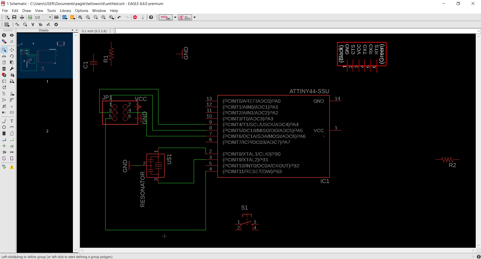
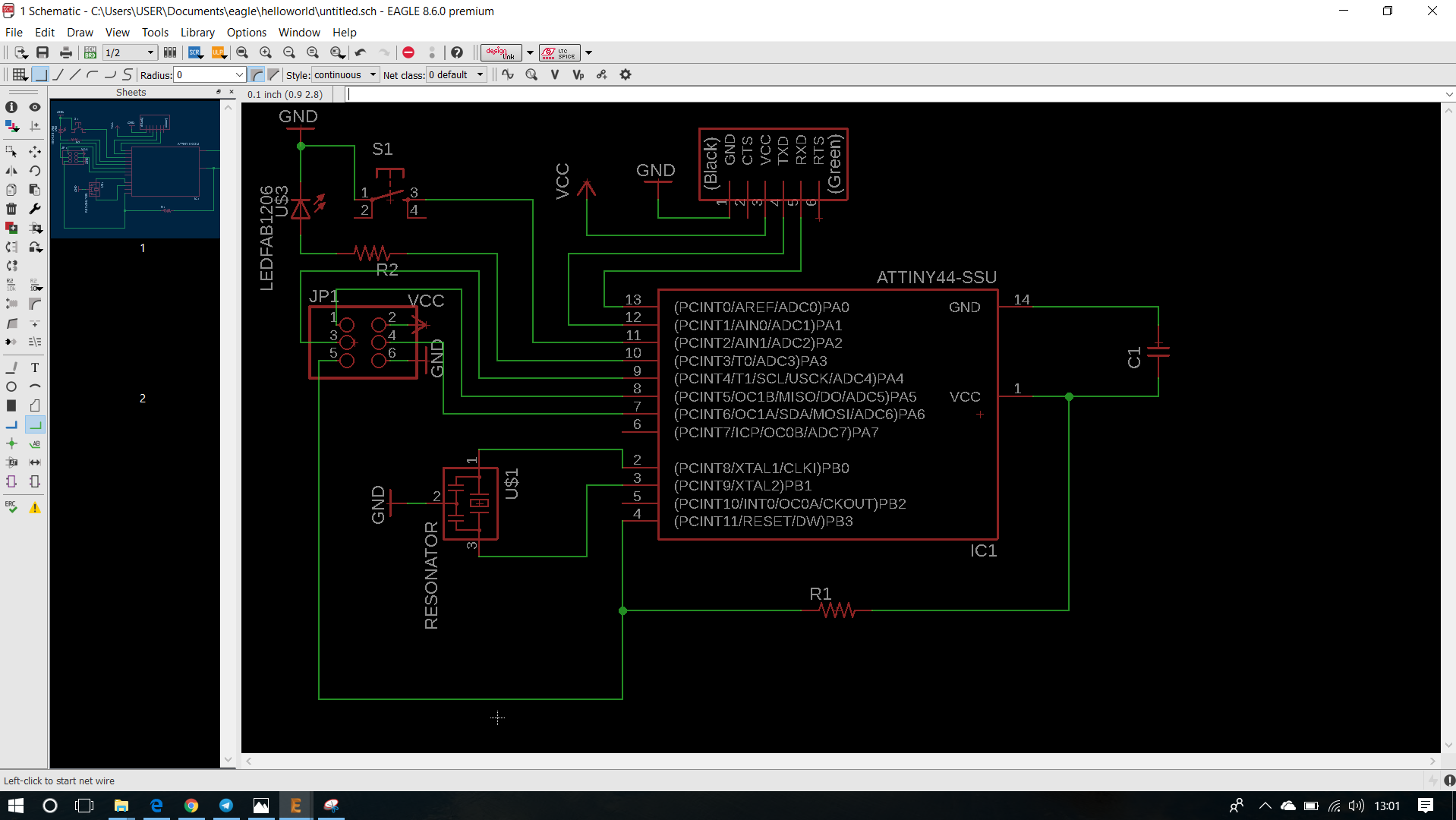
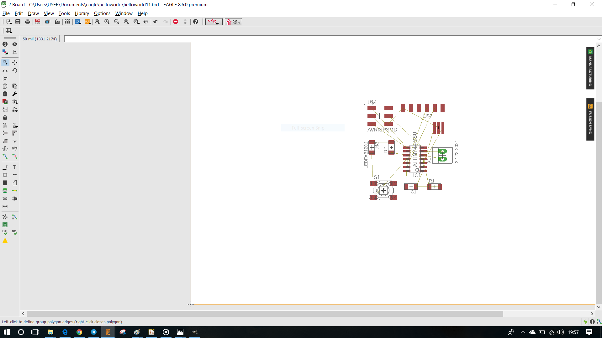
After completing the schematic circuit , check for any ERC errors and then Switch to Board View
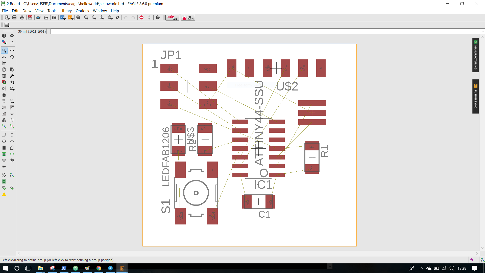
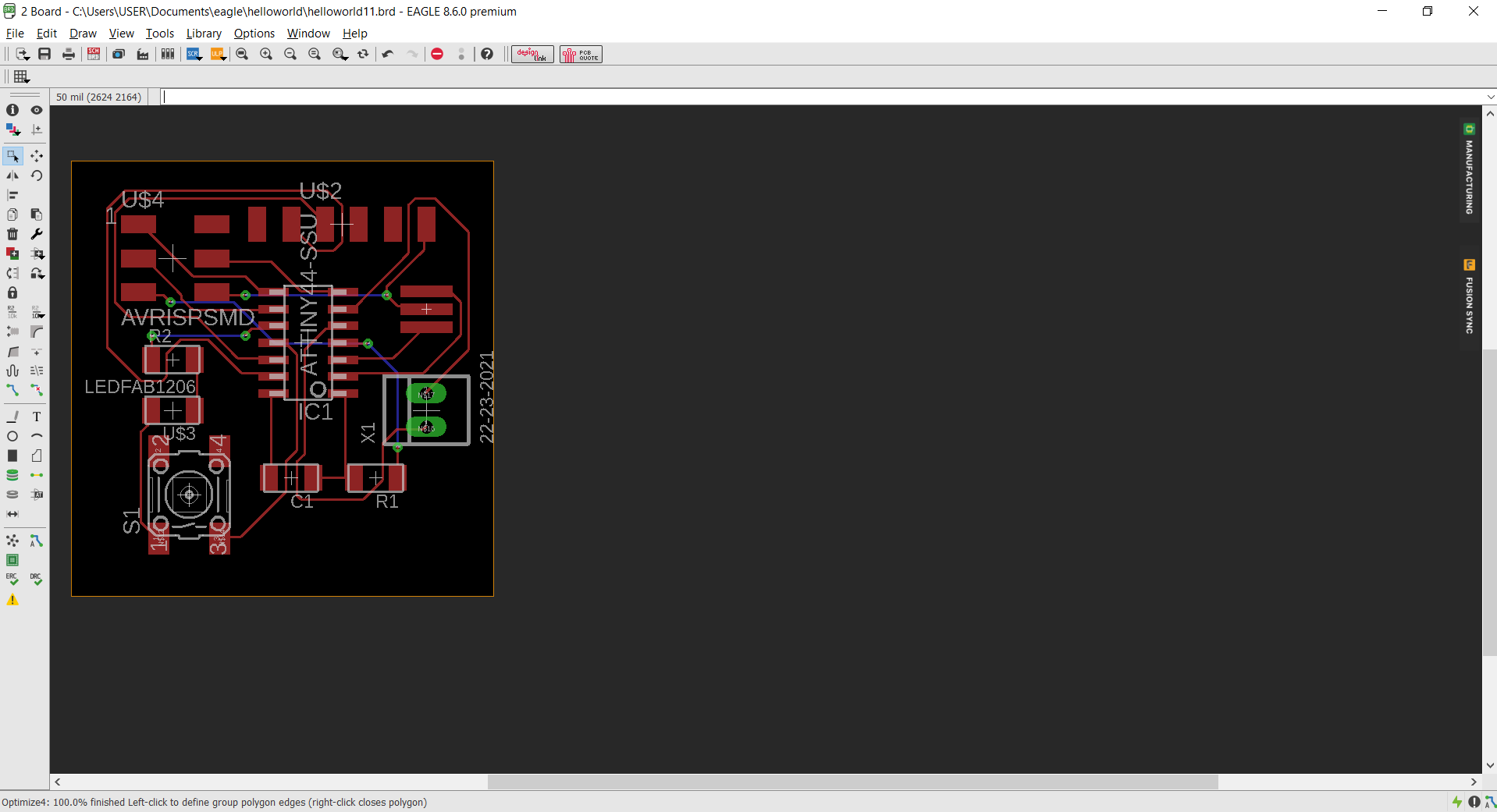
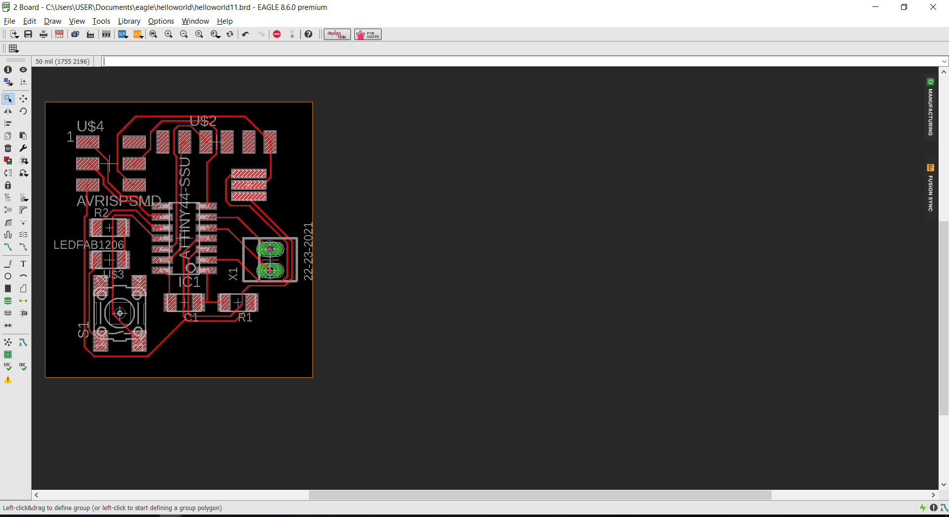
In Board view we have to assemble all the components .
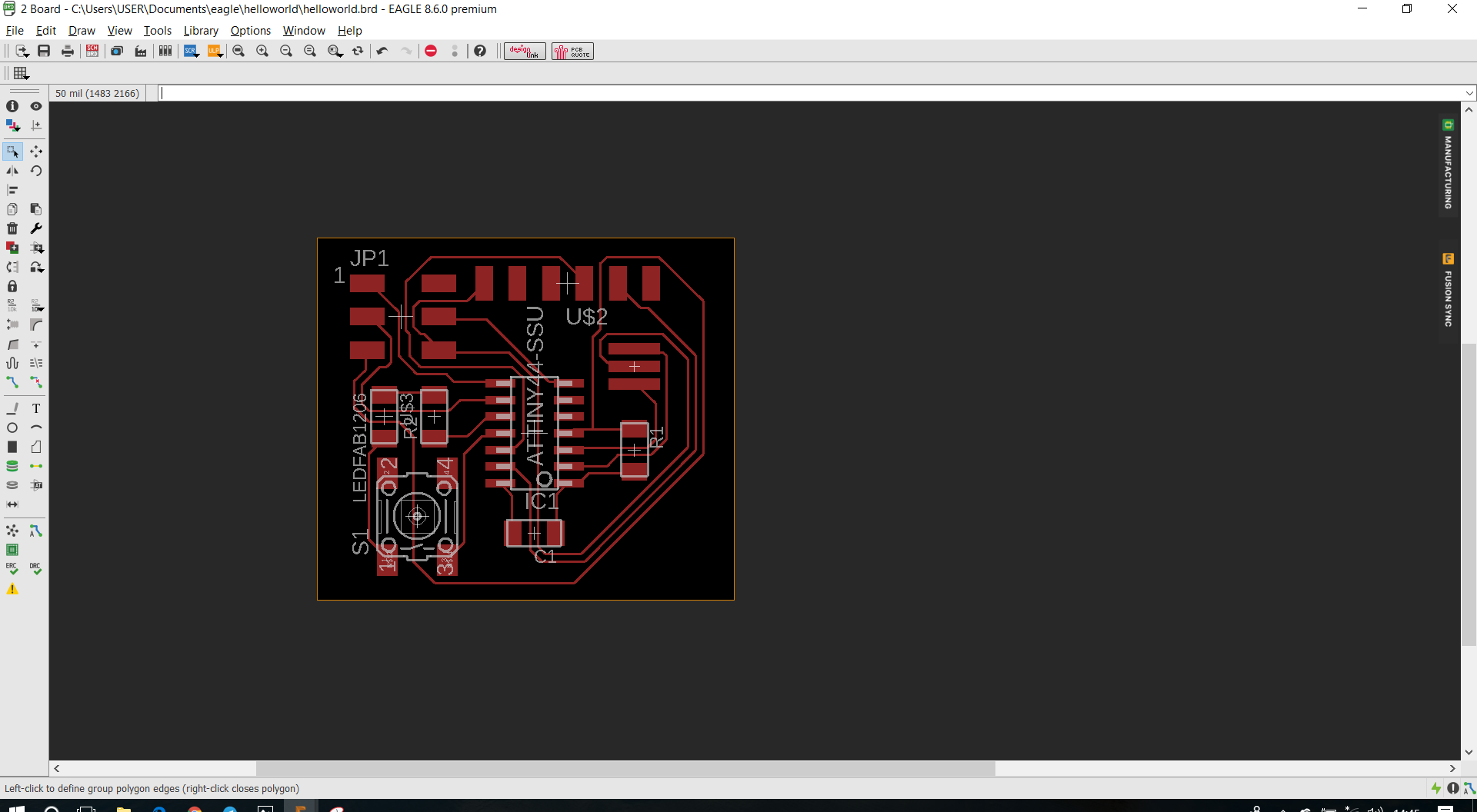
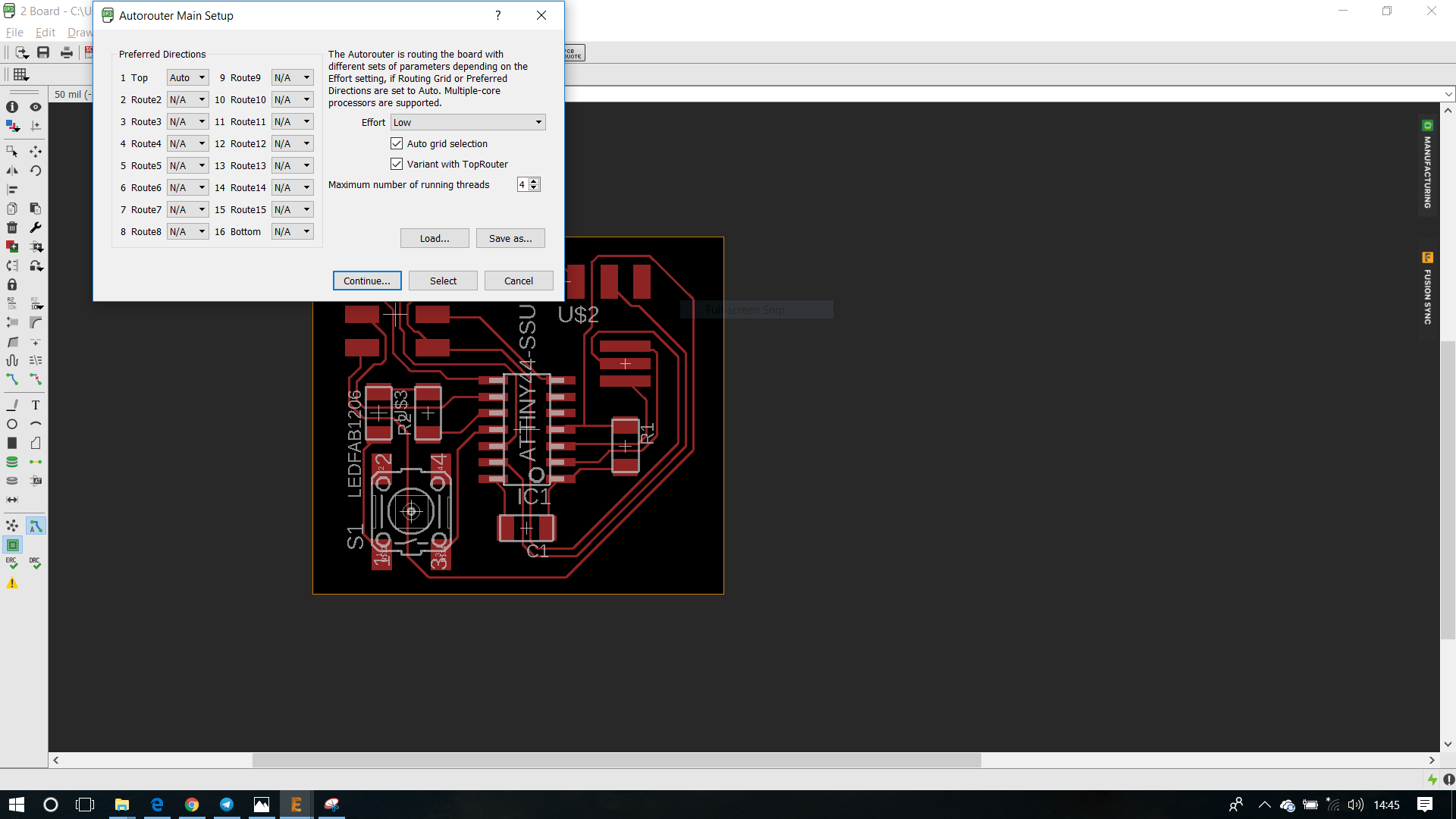
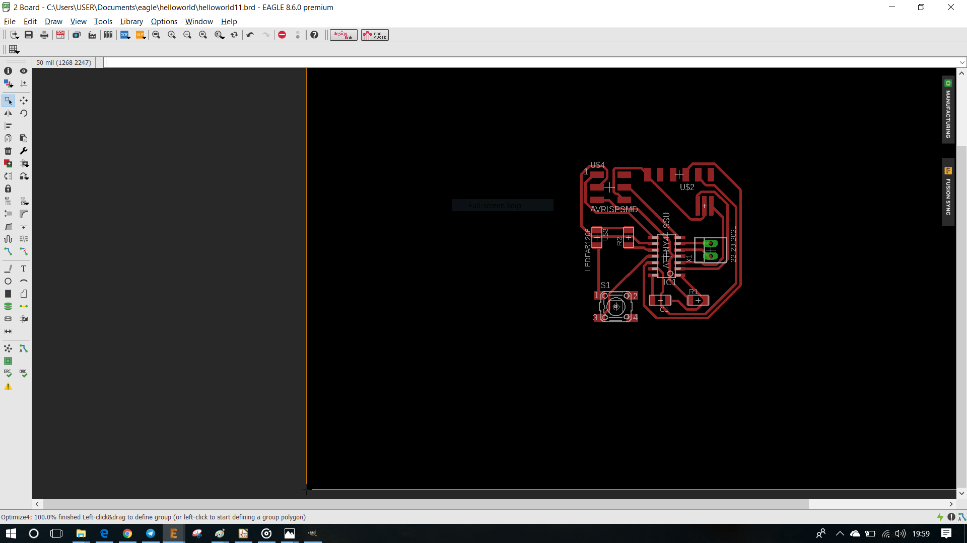
Then we could auto route it to check for any errors
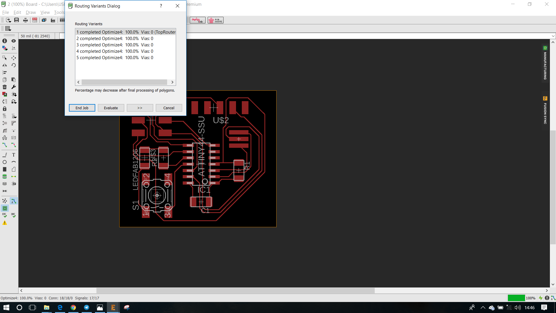
We could choose the top route
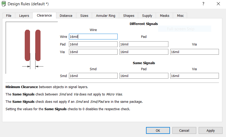
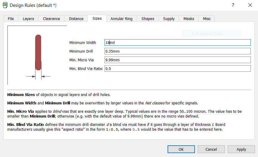
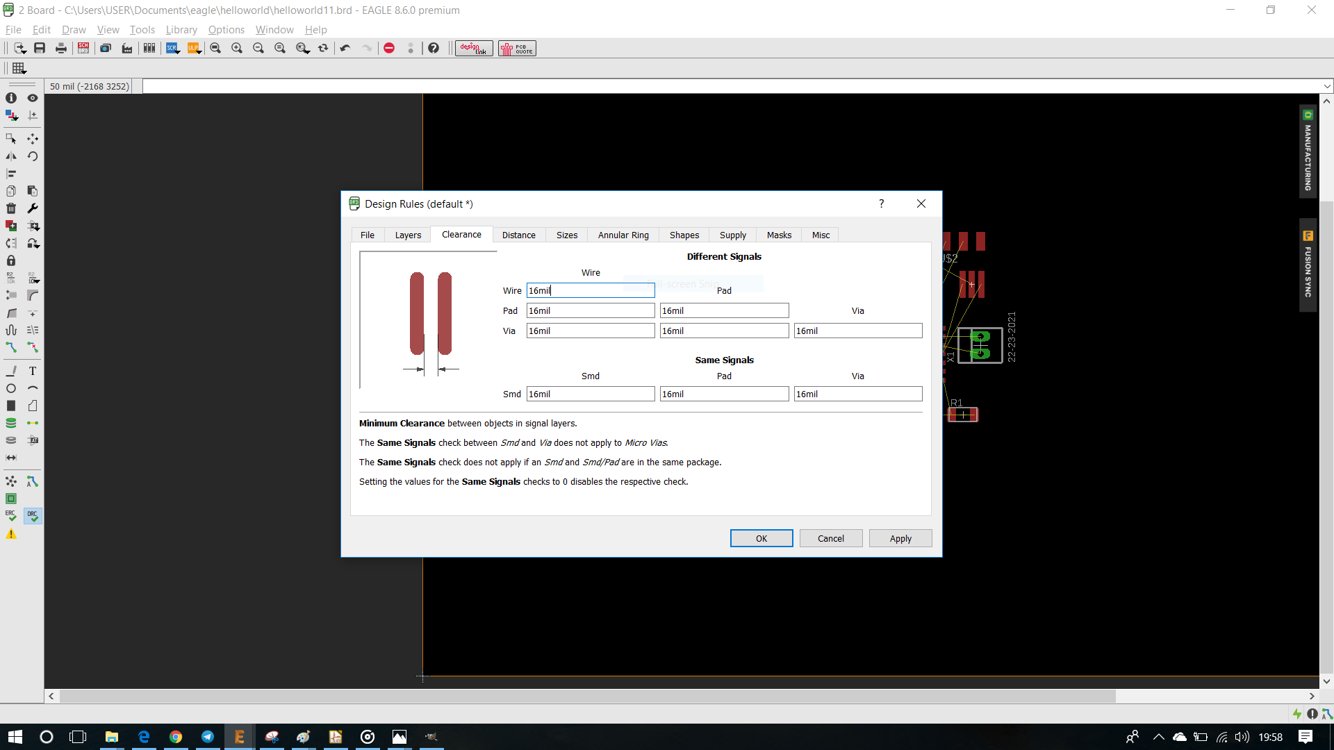
Design Rules
We use a mil as unit of measurement while designing and milling a PCB.
1 mil = 0.0254 mm
As our drill bit for tracing the PCB is 16mil , we change all the width and clearance to 16mil , see below
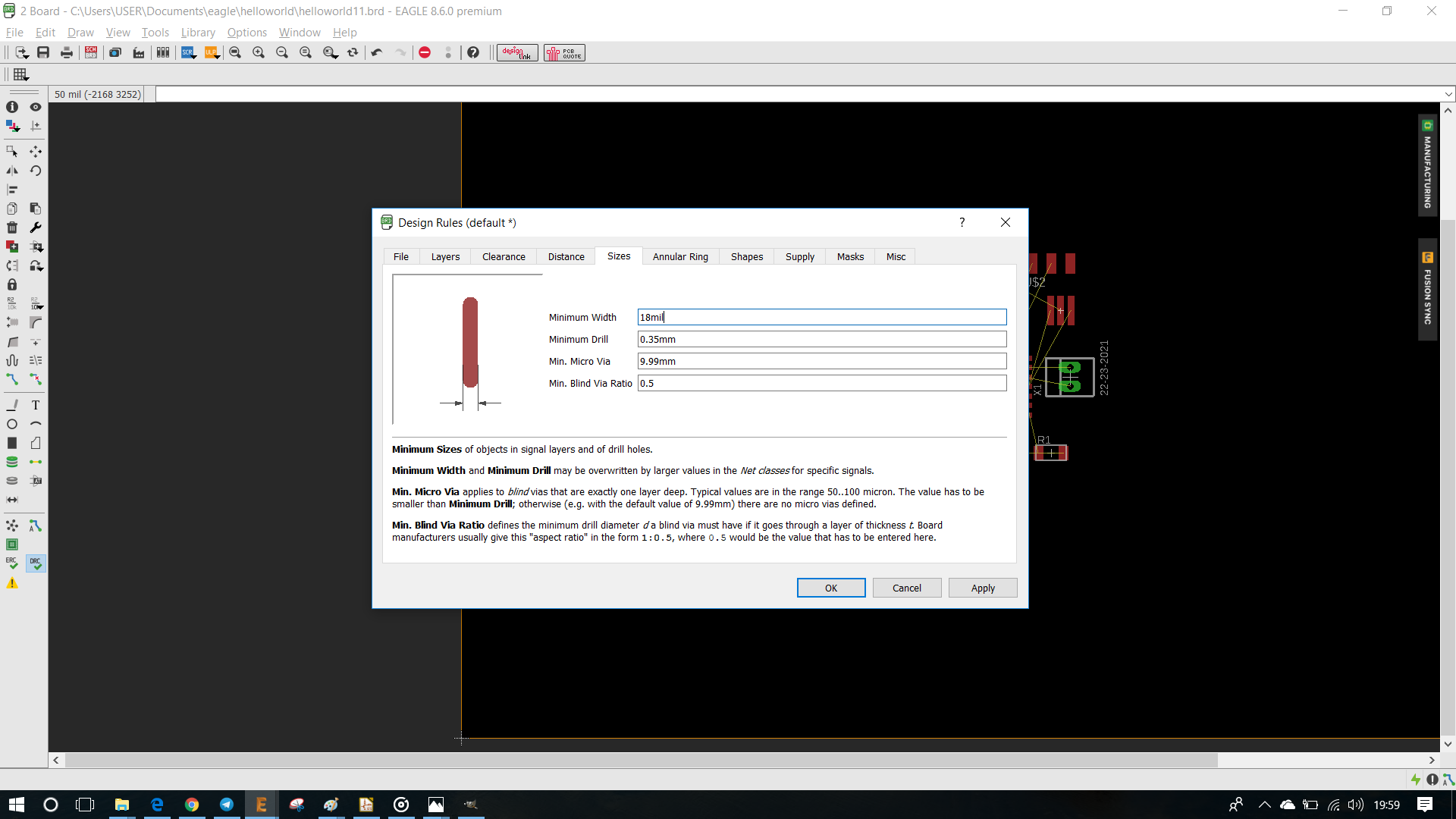
And for the cutting outline of PCB we use 18mil width, see below
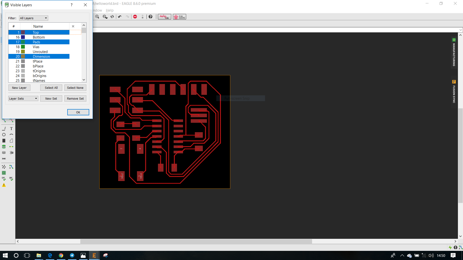
Layers Tool
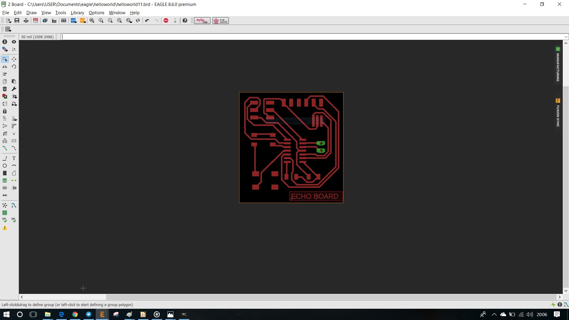
We can use layers tool to filter and view different sections of the board for eg: Top Bottom

Adding a extra two Pin header to the board
With the Text command i named and added a text to the below of board as ECHO BOARD
Download the design files Echoboard Design Files
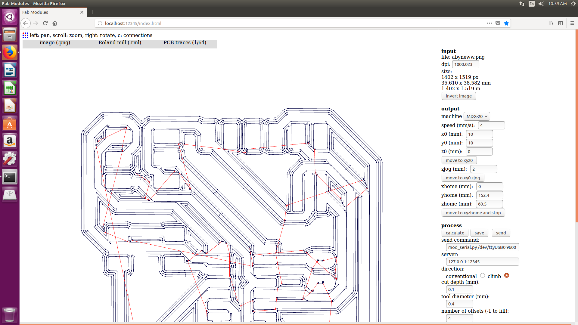
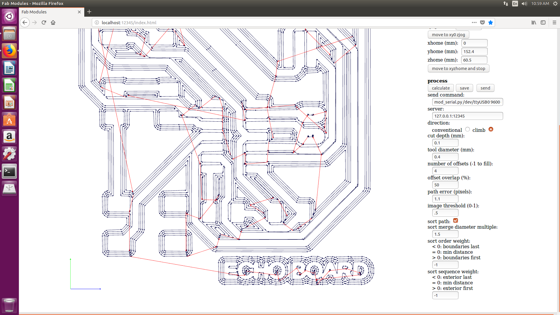
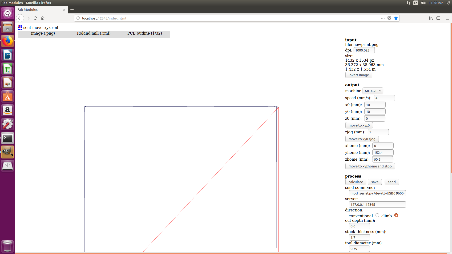
Exporting the png file for the Milling Machine
For the tracing file we have to select only the layers - Top and pads
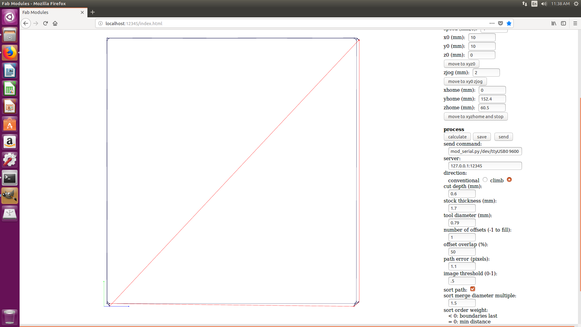
For the PCB outline or cutting file , we have to select the deminsions filter in layer tool.
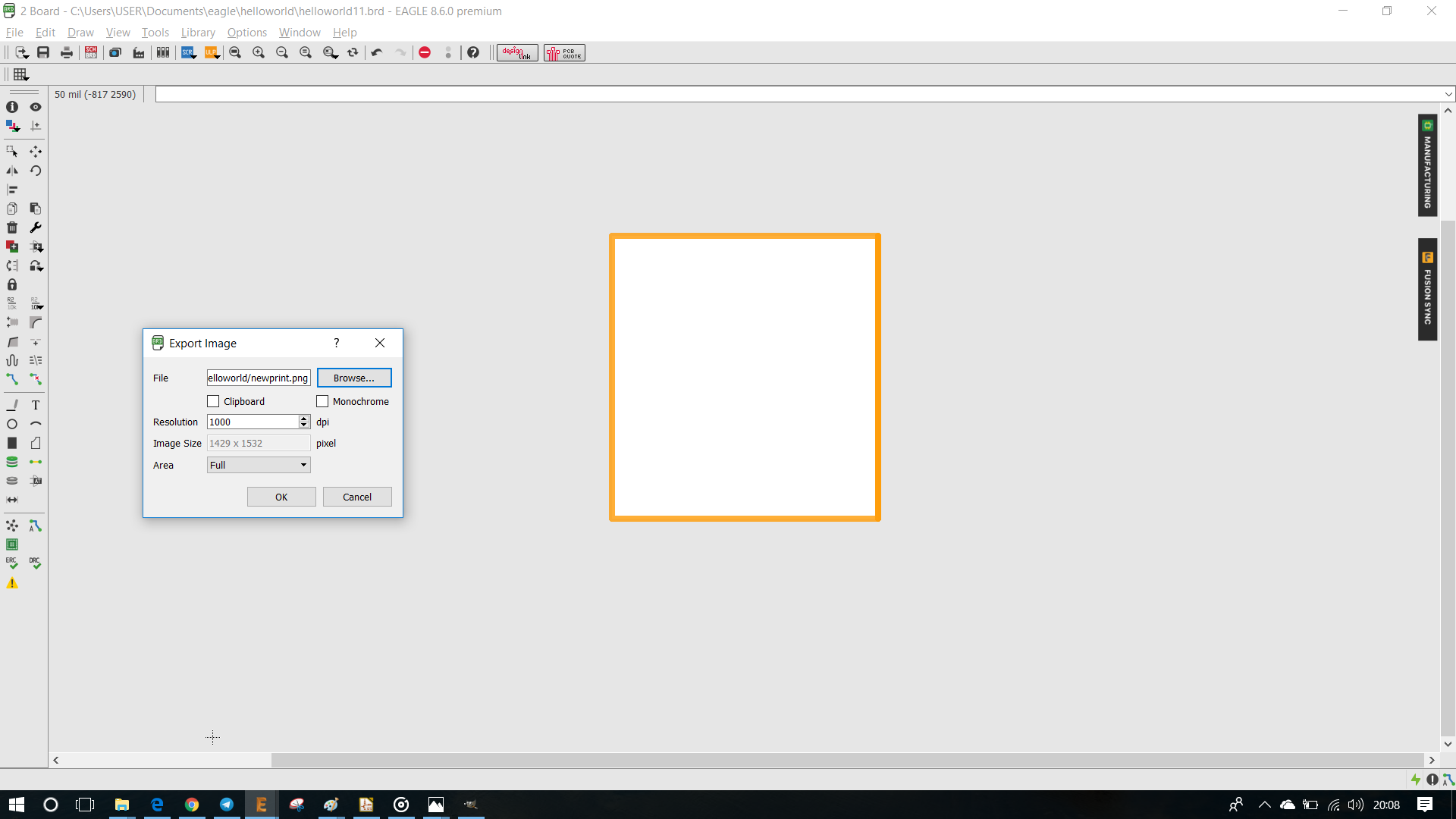
Then we have to export both the files separately as png files, see below for export as png settings
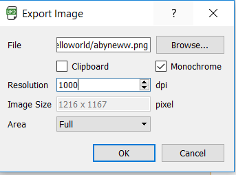
See below the EchoBoard png and the Settings in Fab Module
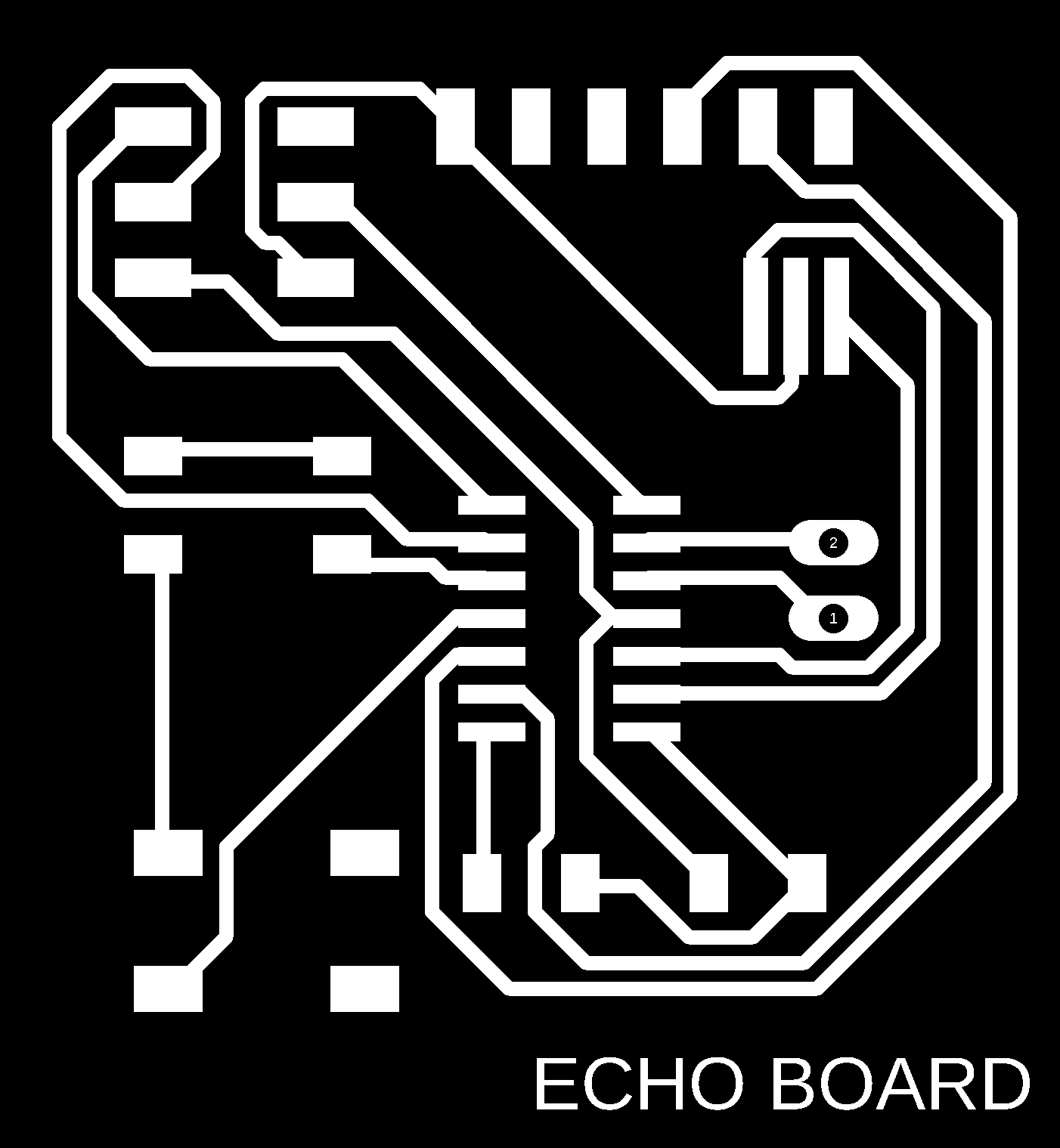
Download the trace file Echoboard File
See below the EchoBoard Cut File png and the Settings in Fab Module

Download the trace file Echoboard Outline File
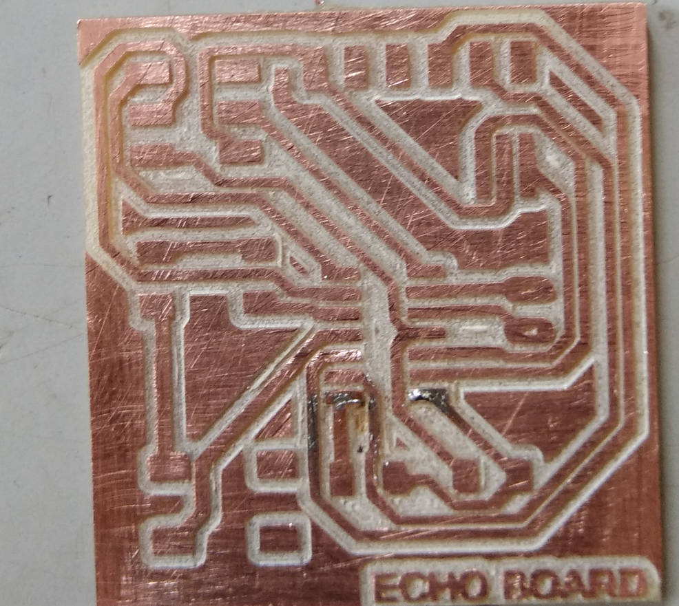
Board and Board Assembly
After milling the PCB , i cleaned the board with a cloth and then scrubbed it with a blade to give a finishing touch
See Below
Now I collected all the components necessary for the Board from our Store, See Below list
Soldering
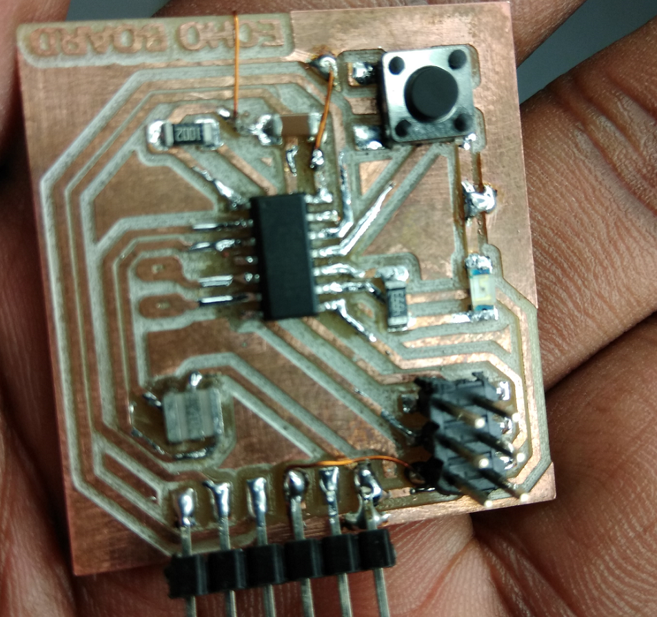
Now i started soldering the board
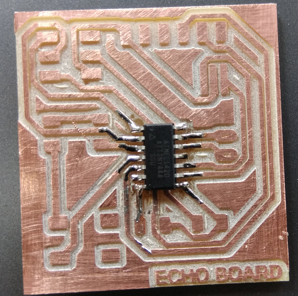
Now my board is ready
Checking the board
I checked the connections of my board with a multimeter, it was then i realized it had some problem with the connections.
After some checking, i found that there were some connections missing between the VCCs and some between the common Grounds. I had my schematic diagram correct but i had given common VCCs and Gnds to the circuit so when i switched it to the board view, the common VCCs and GND weren't connected. And when i milled the board, the traces joining the VCC pins(also GND) pins were missing.
Now I have to make it work somehow, with the help of my Lab Instructor Vinod , I somehow managed to find a solution.
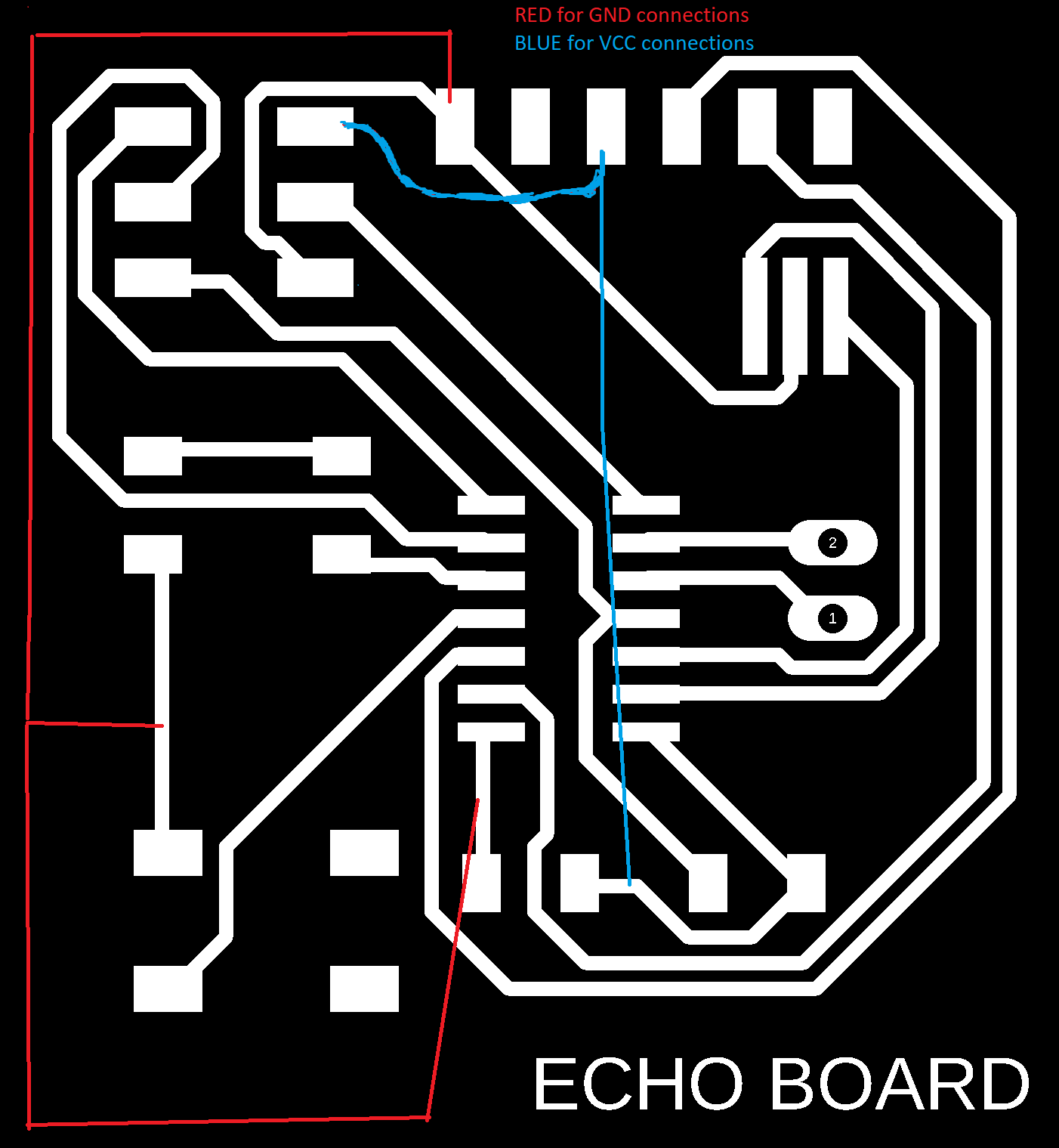
First of all I decided to manually edit my PCB trace file, i draw the missing connections of VCCs and GNDs, See Below Image , i gave red colour for the GND connections and Blue for VCCs.
Then i tookout my board to the soldering station.
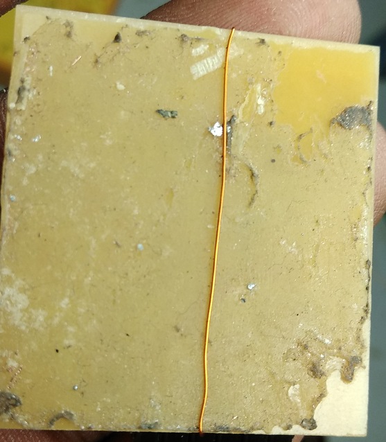
Board with corrected connections
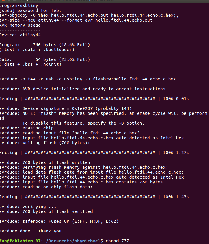
Programming the Board
Checking whether my board would work.
I connect my FabIsp to the USB port of the computer and with a FRC cable i connected it to my Board(2x3pin header).
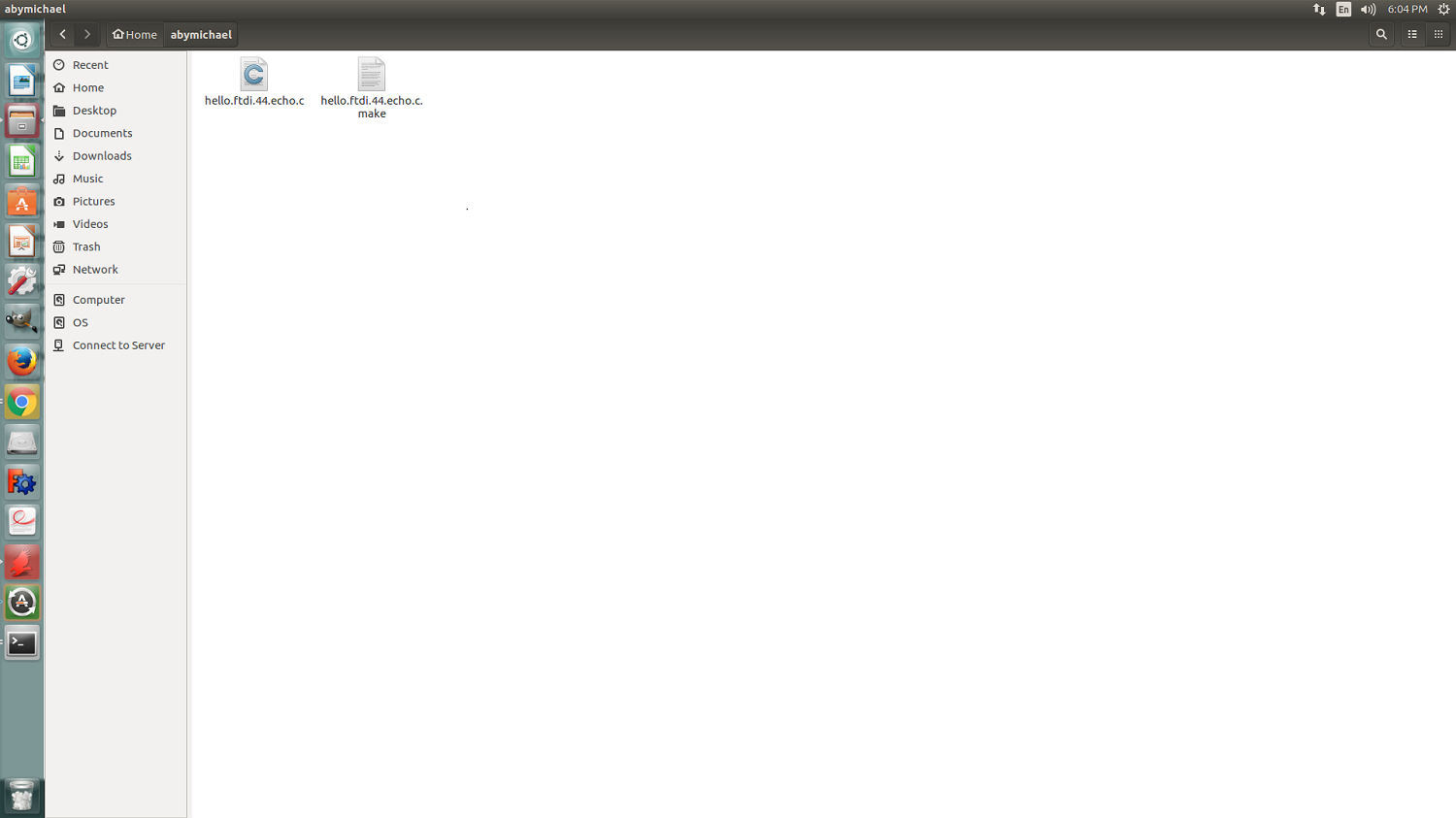
There is an example of how to program in our Schedule ProgrammingDownloaded the hello.ftdi.44.echo.c file and hello.ftdi.44.echo.c.make file

Group Assignment
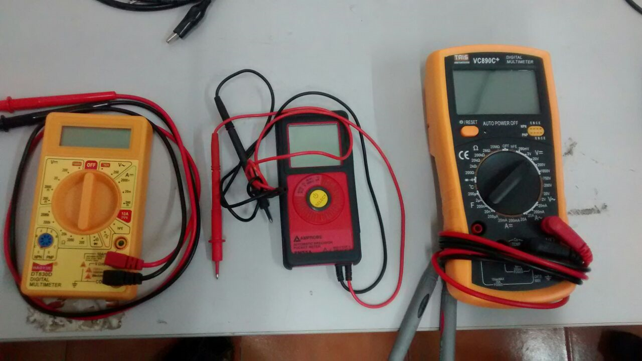
We need to use the test equipment in our lab to observe the operations of a microcontroller circuit board
an instrument designed to measure electric current, voltage, and usually resistance, typically over several ranges of values.
It is a Programmable Multiple Channel DCPower Supply Device
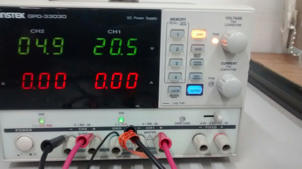
Later on I used this machine for testing the voltage and current flow in my boards and for getting the output volatage to run the DC motors.
An oscilloscope, CRO for cathode-ray oscilloscope, or DSO for digital storage oscilloscope, is a type of electronic test instrument that allows observation of varying signal voltages, usually as a two-dimensional plot of one or more signals as a function of time. Other signals like sound or vibration can be converted to voltages and displayed.
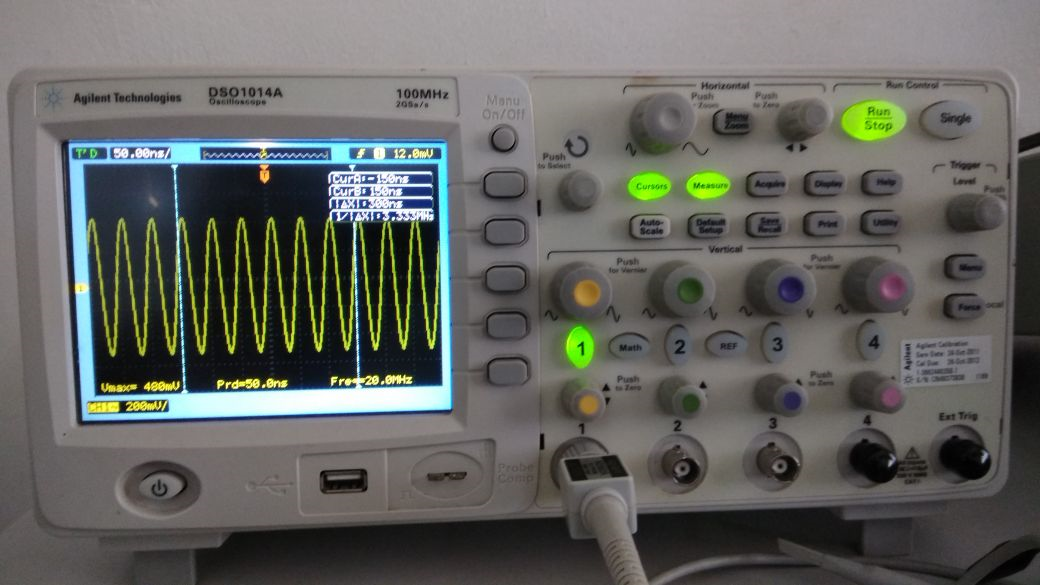
Later on I used it to test the output signals from the programs I flashed in my boards.
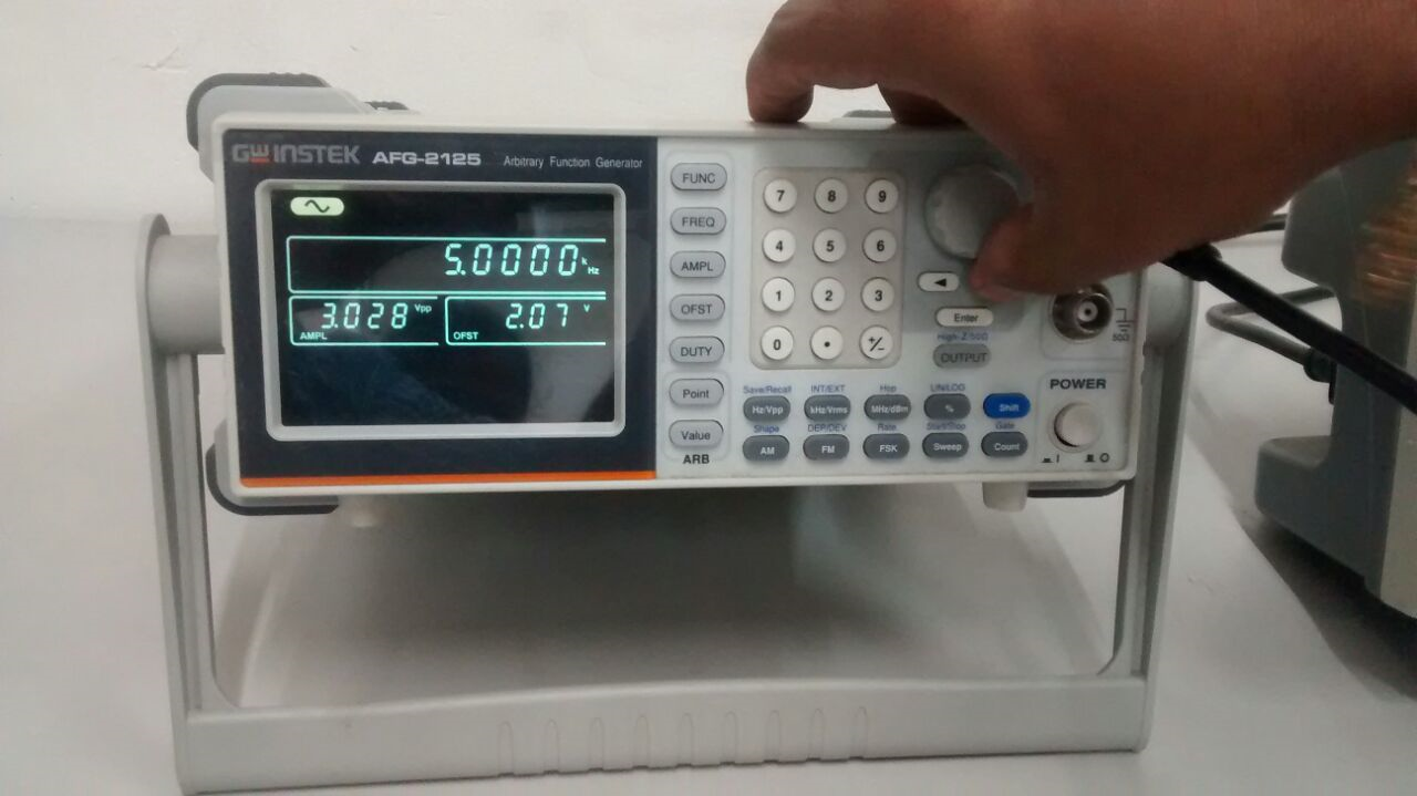
An arbitrary function generator is a piece of electronic test equipment used to generate electrical waveforms
Outcomes of the Week
This work by Aby Michael is licensed under a Creative Commons Attribution-NonCommercial-ShareAlike 4.0 International License.
