Week 4
Computer Controlled Cutting
We were introduced into the different types of tools available for Computer Controlled Cutting with special emphasis on Laser Cutter & Vinyl Cutter. We were also introduced with parametric design and the idea of press fit kit. This weeks group assignment was to characterize the lasercutter available at our lab by making test parts by varying the settings and dimensions. Individual assignment was to cut something on the vinylcutter and to design, lasercut, and document a parametric press-fit construction kit, accounting for the lasercutter kerf, which can be assembled in multiple ways
Characterising the Laser Cutter
A laser cutter uses a laser beam to burn the material to make an impression. By varying several aspects of the quality of beam, the laser cutter can make a cut or engrave. Engraving is made by making a cut of shallow depth, atop the material.
Kerf: Laser beam has a thickness of approximately 0.1mm. Due to the burning, a portion of the material is lost after the operation. The quantity of material burned will depend upon the type of material and also the depth of the material. Kerf is the quantity of burned materials, and is expressed in length (width of the cut).
The laser cutter we have at our lab is the 'Trotec Speedy 100'. The "Air Assist" for the laser beam is sucked out with an exhaust system consisting of an air pump and filter. The output of the air pump is chanelled outdoor through a pipe.
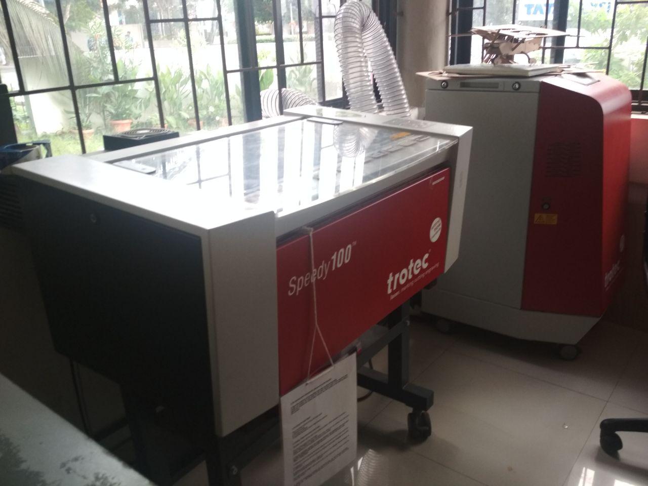
The "Air Assist" removes the smoke during the operation and ensures that energy of the beam is not dissipated in the smoke. It also reduce the build up of deposits on the focus lens. Correct focusing of beam onto the material ensures that maximum energy hit the target area so as to make a proper cut or engrave. The focus of the beam is adjusted with the tool in the image below. It will be delicately hung from laser head, and the bed will be set to focus by raising the bed gently to just topple the tool from its hung position.
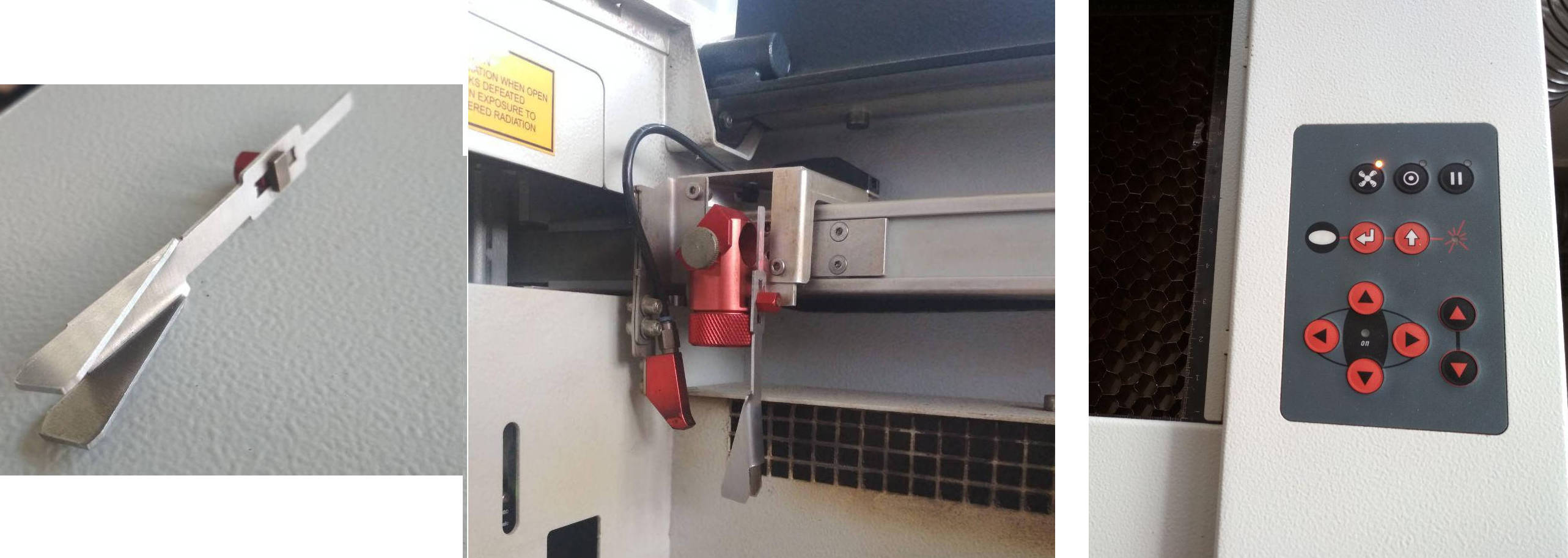
The laser head can be moved in the hozontal plane by using the buttons on the right side of the machine. The bed is also moved up and down using the buttons.
The laser cutter is never to be left unattended during operation for the chances of fire break out. Also, PVC should not be exposed to the laser for the toxic fumes it creates.
The laser will make a cut along the strokes in the design and will make an engrave over the fill area in the design. The strokes should be in red colour, and the fill in varying degrees of black to get varying depth of engraving. Inkscape is a good tool to easily convert our 2D design file to fit into the software for the laser cutter. The fill area and the width and colour of lines in the design can be adjusted using the "Stroke & Fill" option in Inkscape.
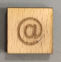
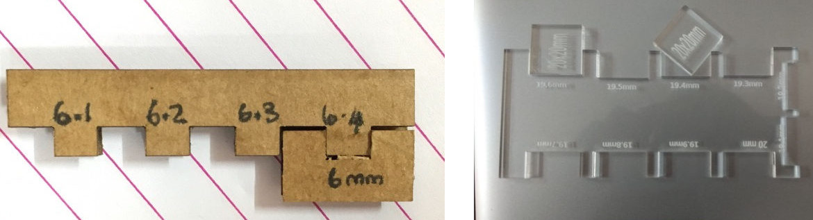
We made test cuts in 3mm craft plywood, 3mm acrylic and 4mm cardboard. A design of a rectangle of size 20mm x 20mm was made with the symbol "@" in the middle of the rectangle. 3mm craft plywood was cut using the design by varying cutting parameters to get the perfect cut. Engraving of the symbol was also done. We measured the size of the cut piece and found to be 19.7 x 19.7 mm. Hence the Kerf for 3mm plywood is 0.3mm. The same was repeated with 4mm cardboard and 3mm acrylic and the Kerf was measured as 0.2 and 0.3mm respectively. We also designed and cut comb's to identify the optimal fit.
Laser Cut and Engraving of Acrylic was done for the Final Project
Parametric Design in SOLIDWORKS
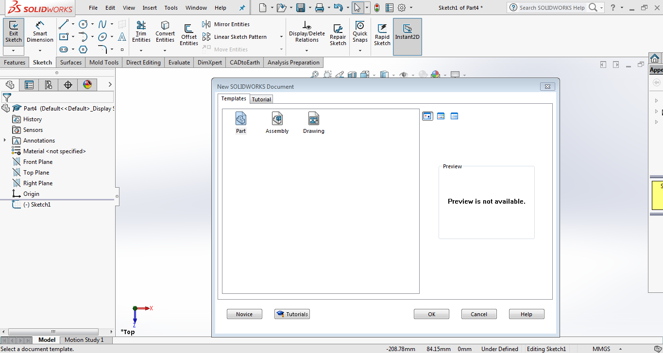
A new file was opened in SOLIDWORKS by clicking File > New. Part template was selected in the newly opened window.
By clicking the
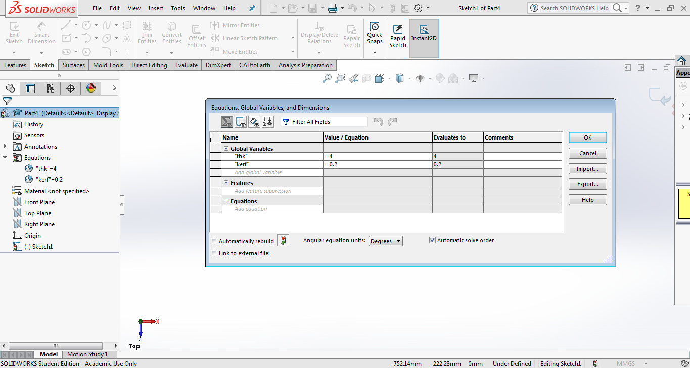
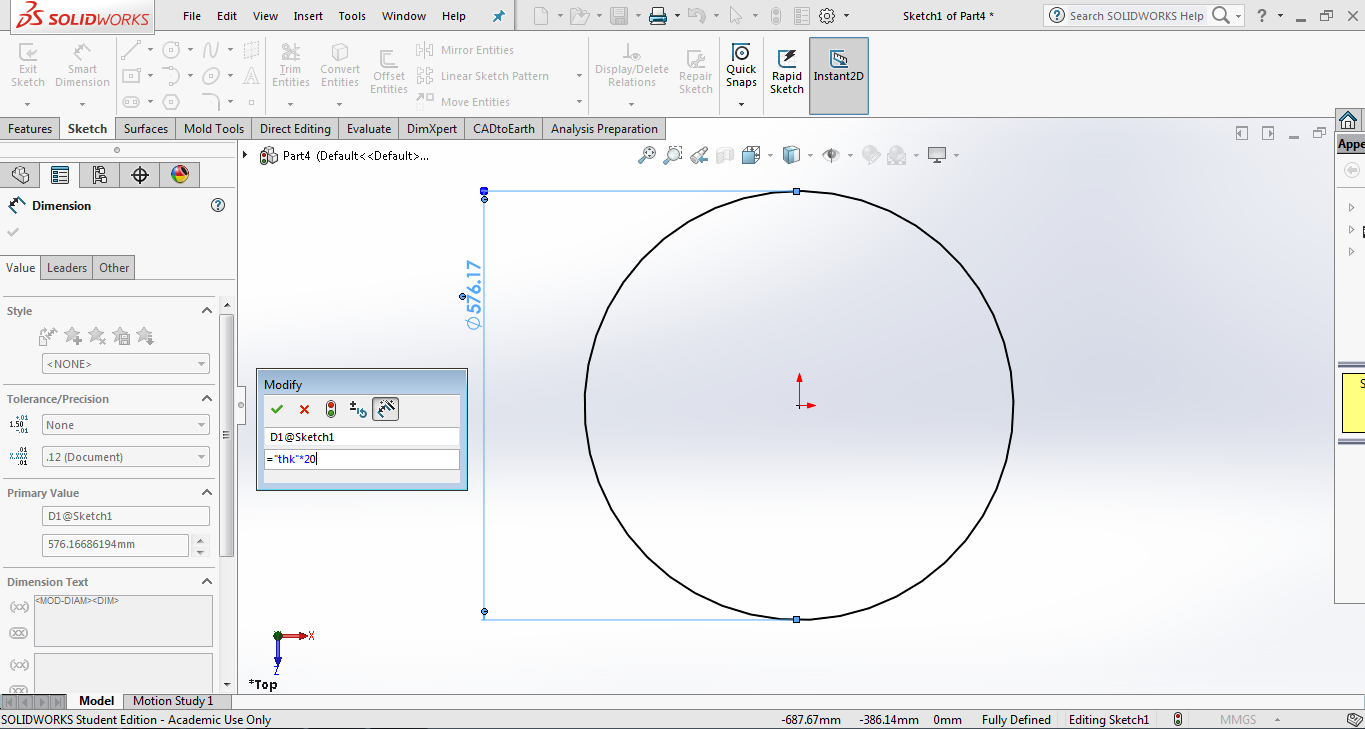
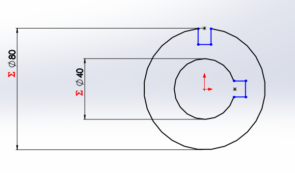
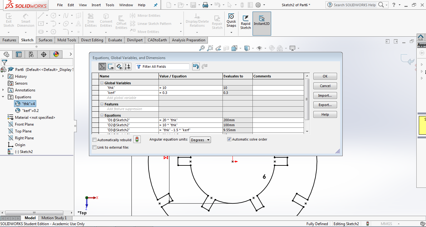
The design was made parametric with respect to two variables, thickness and kerf. The thickness was defined with a variable “thk” and was set to 4mm. The kerf was defined with a variable “kerf” and was set to 0.2mm. These are the global variables which was used for the parametric modeling. By selecting Tools > Sketch Entities > Circle, a new circle was created at the origin. By selecting Tools > Dimensions > Smart and clicking on the circle, a new dimension Modify window was opened, in which the diameter was defined using an equation with “thk” as the variable. The diameter was set to 20 times the thickness. The same can be changed by double clicking over the dimension.
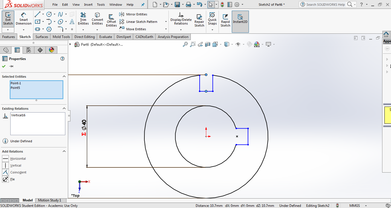
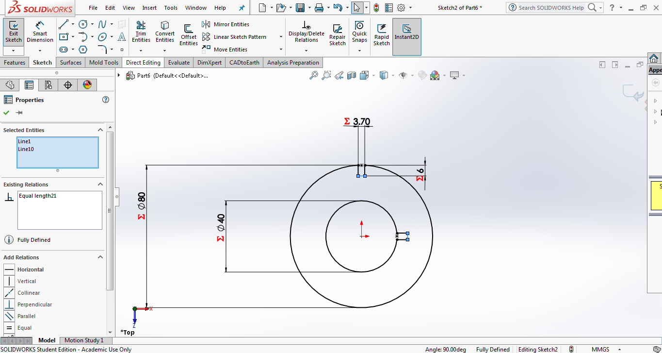
Another circle was drawn at the origin and the diameter was set to ten times the thickness. Now it was time to draw the slots for the press fit construction. The width of the slots have to take account of the laser cut kerf. The width of slot will increase by an amount equal to half kerf on each side and hence the width of slot has to be kept one kerf width smaller. I chose to keep it 1.5 times smaller so as to take in account of the variation of thickness in the cardboard available at our lab. By selecting Tools > Sketch Entities > Centre Rectangle, two new rectangle was created with its centre at the point where the bigger circle meets the Y axis and also at the point where the smaller circle meets the x-axis.
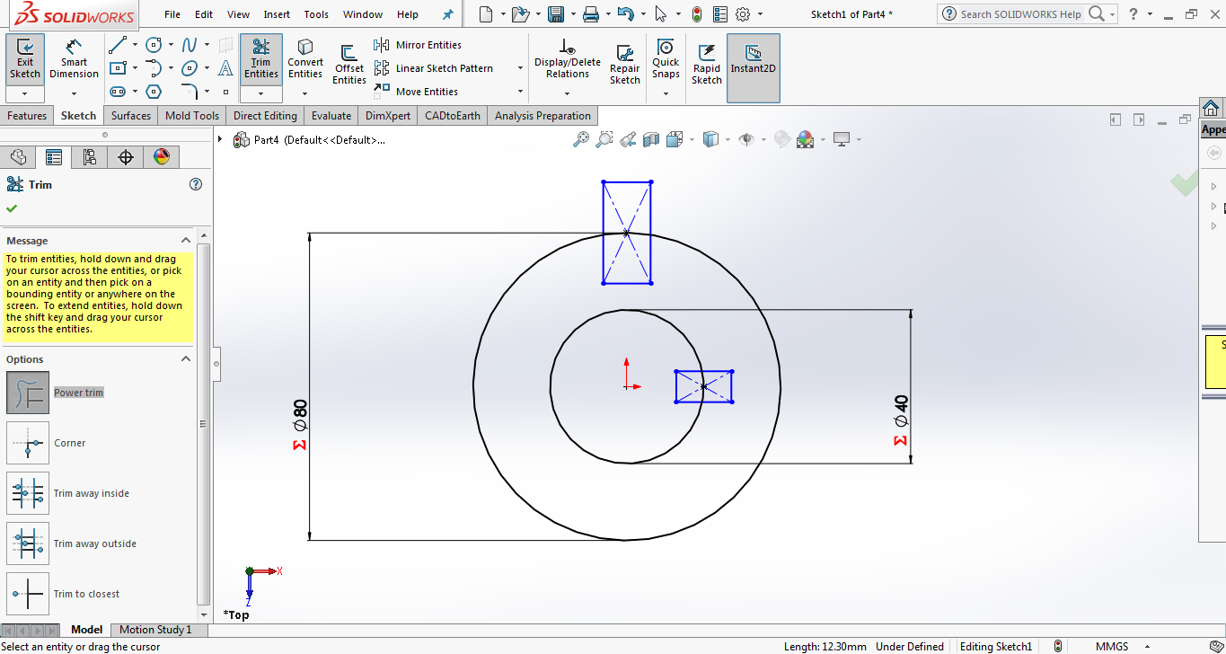
By selecting Tools > Sketch Tools > Trim, the unwanted portions of the rectangle was trimmed off.
For maintaining the symmetry when the width of slot changes, the centre of the two rectangle were made in line with the respective axis. The centre point of the rectangle on the outer circle was restrained vertically by adding a vertical relation with the midpoint of the slot width. Similarly a horizontal constrain was set to the rectangle on the inner circle.
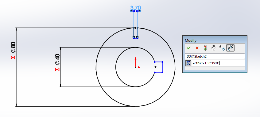
By using the smart dimension option, the dimensions of the slot was then changed with the width of slot = thickness – (1.5 times the kerf)
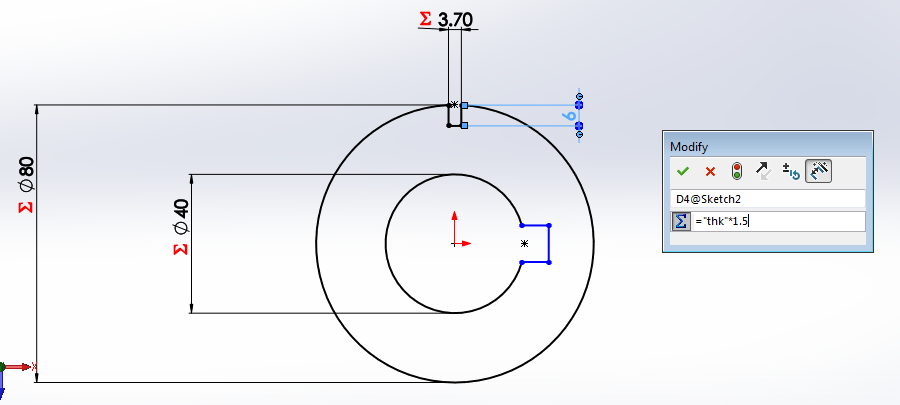
Likewise the length of slot was made = 1.5 times the thickness.
The equality constrain was then applied between the slots between its length and width.
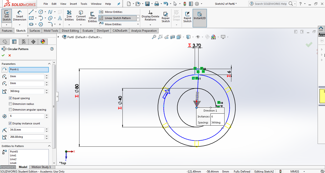
Now using the circular pattern option in Tools > Sketch Tools > Circular Pattern, the slot was made along six directions. These slots carry the same property of the parent one, making the design parametric.
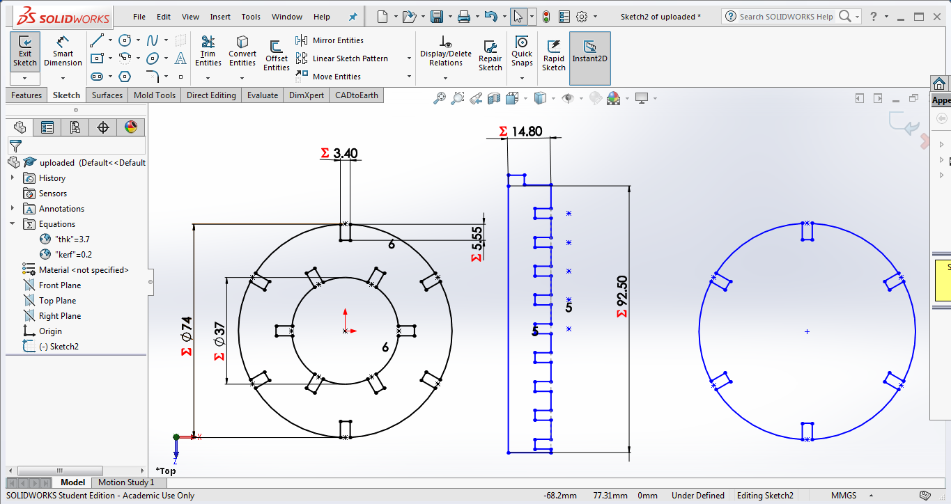
The same was repeated with the slot on the inner circle and after trimming the unwanted portions, the final sketch of the circular element is the one below.
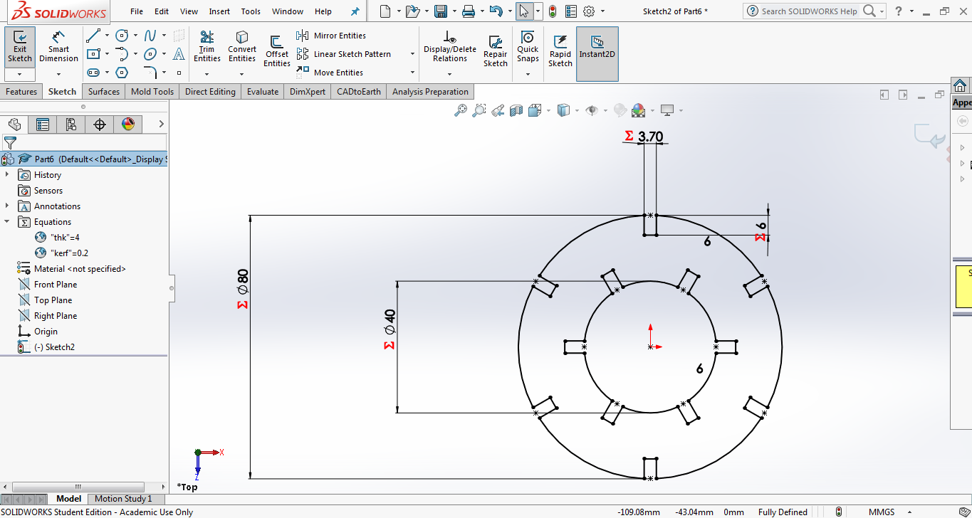
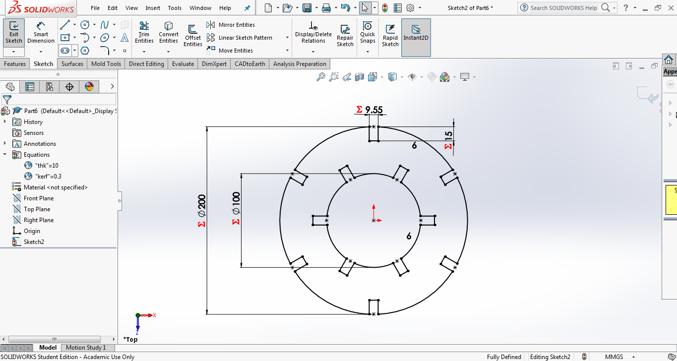
Right clicking over any of the Variable Name under Equations in the left pane will give an option to Manage Equations. Clicking on it will open a new window on which we can change the global variable with which the entire sketch can be changed. The value of “thk” was changed to 10mm and “kerf” to 0.3mm. The equations which drives each curve on the sketch can also be edited from here.
Below is the image of the sketch which was changed by varying the parameters.
Download the design file
Press Fit Kit
A press fit kit when assembled, should stand on its own without any glue or adhesive. Identifying and accounting for the laser Kerf plays a major role in making the parts fit together using friction. The laser kerf should be accounted for while designing the male and female parts of a joint. Working on either parts, individually or combined, the parts can be made to fit together.
One more circle and rectangle was created with the same parameters in SOLIDWORKS for making the kit.
The file was exported as a .dxf file and opened in Inkscape. The document size was set to 60cm x 30 cm, which is the size of the bed of the laser.
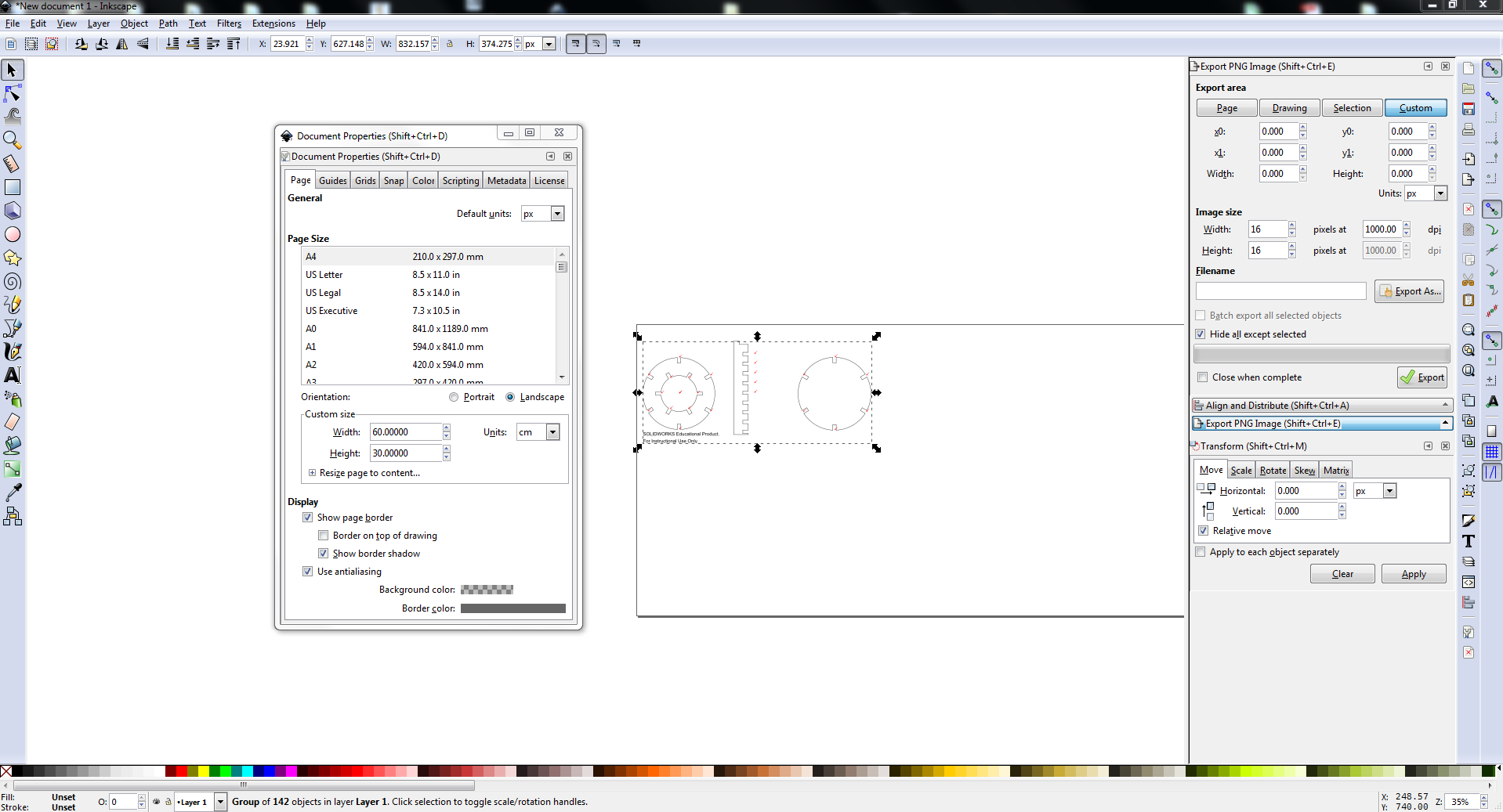
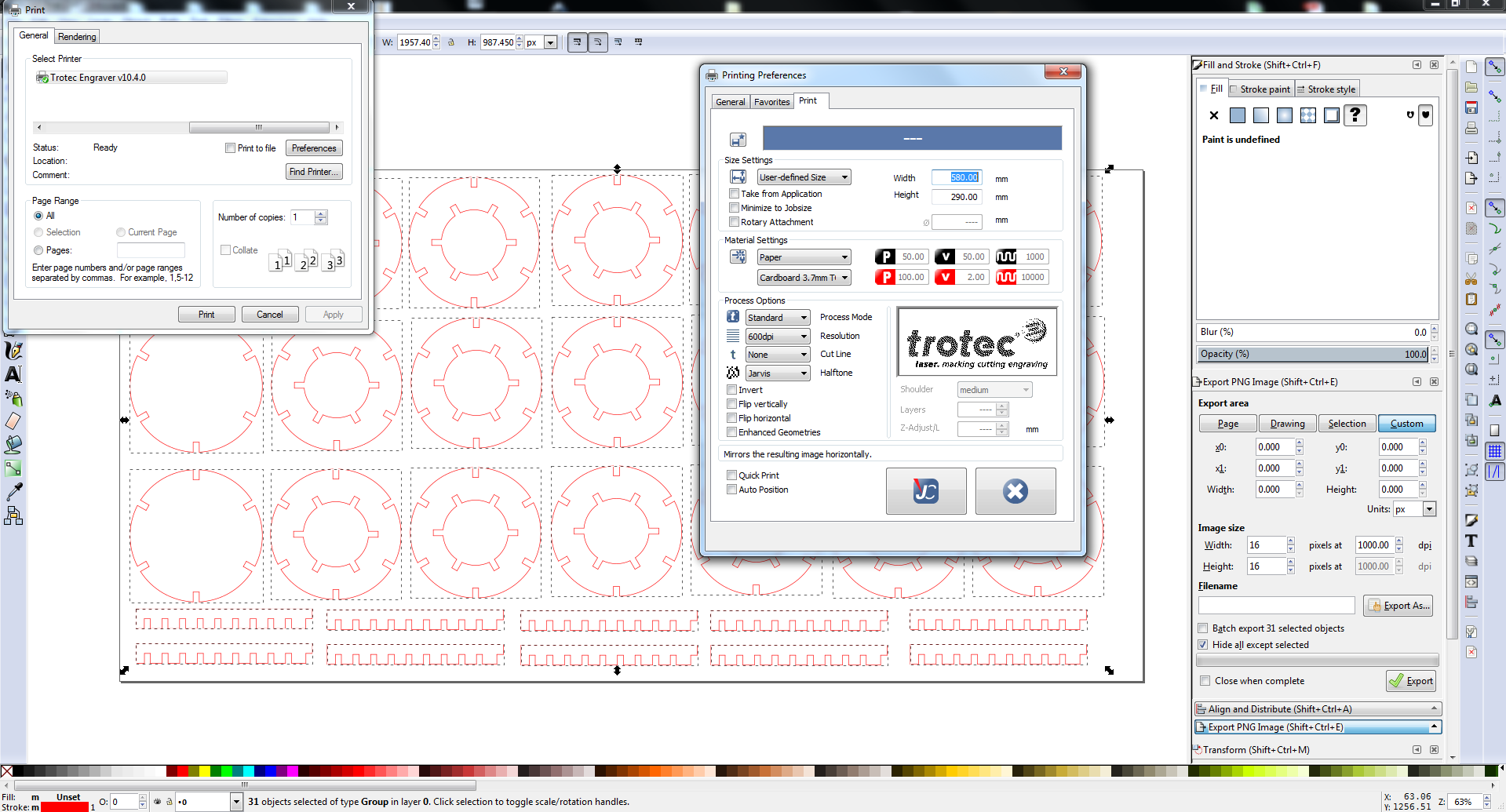
There was some unwanted points(the reference points for the constrains created for the slots in SOLIDWORKS) in the design which was removed in Inkscape. The Stroke size and colour was set to 0.1mm and red respectively. The individual parts were grouped, replicated and arranged within the bed size to make the kit. It was then send to the laser cutter with the setting for cardboard.
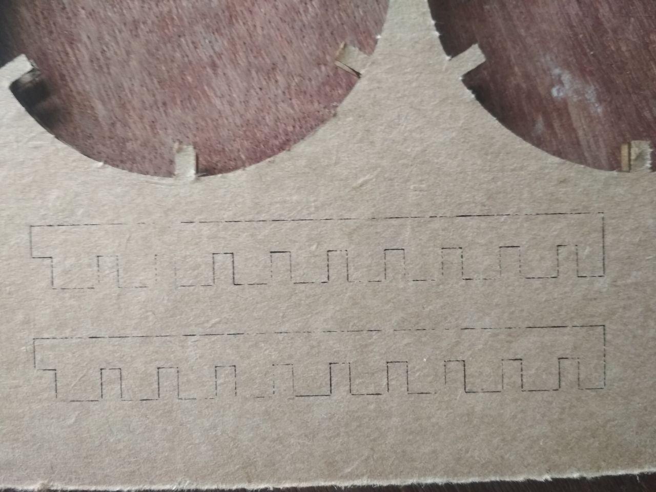
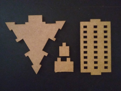
Below is the finished cut.
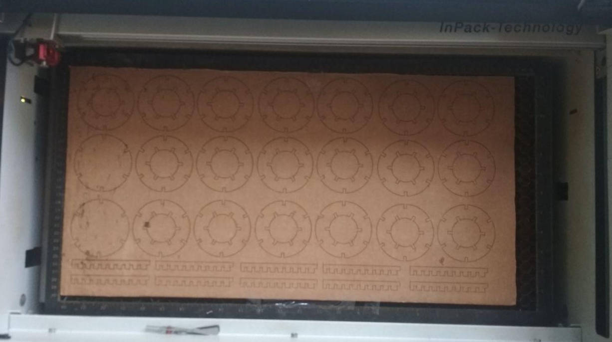
The cardboard was having a bend and i tried to reduce it by holding the cardboard down onto the bed from the sides using a cellotape. Due to this bend which made the beam out of focus, the portion near the rectangular pieces were not properly cut and had to be manually done.
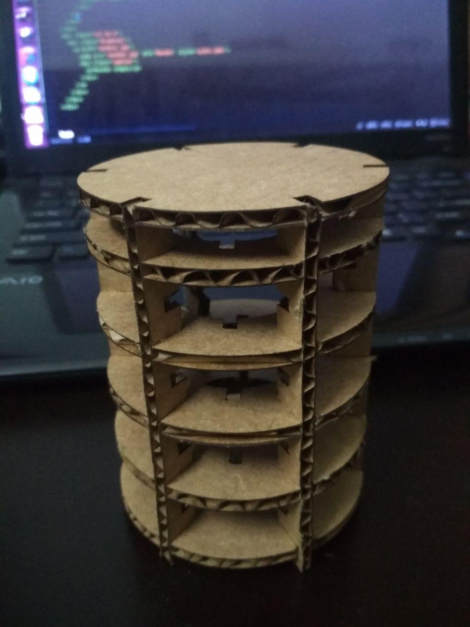
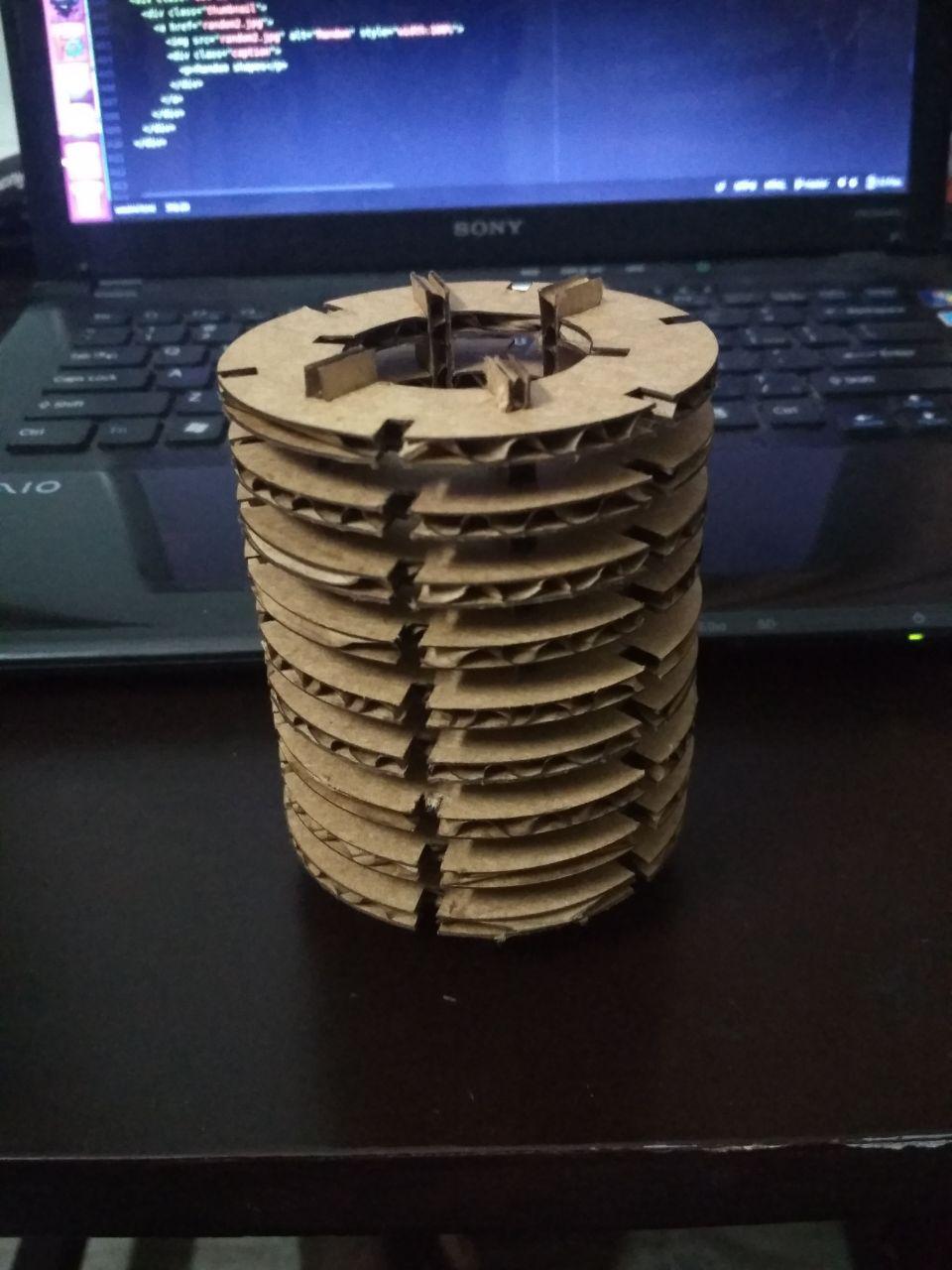
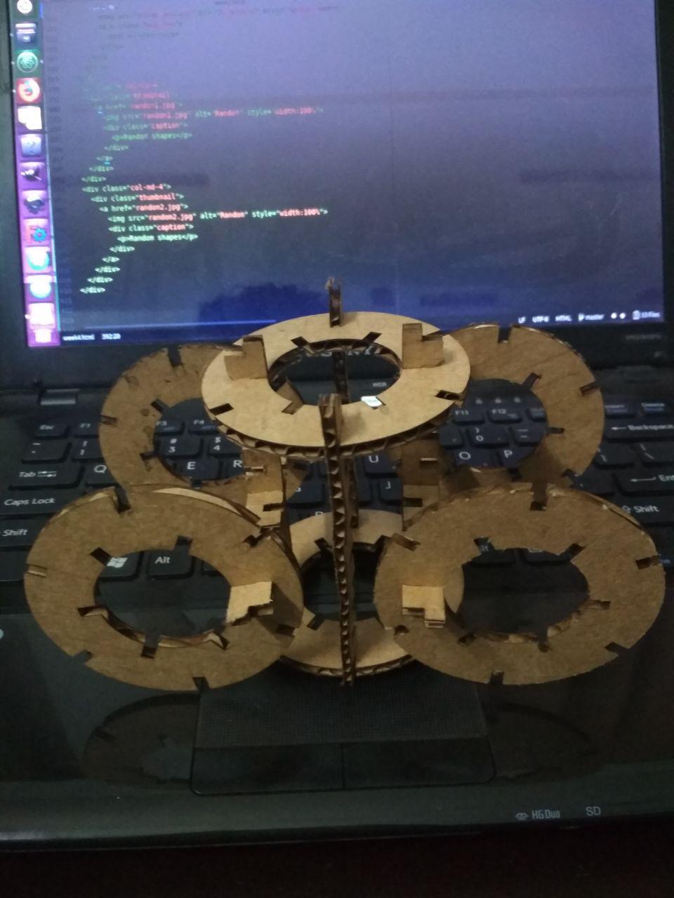
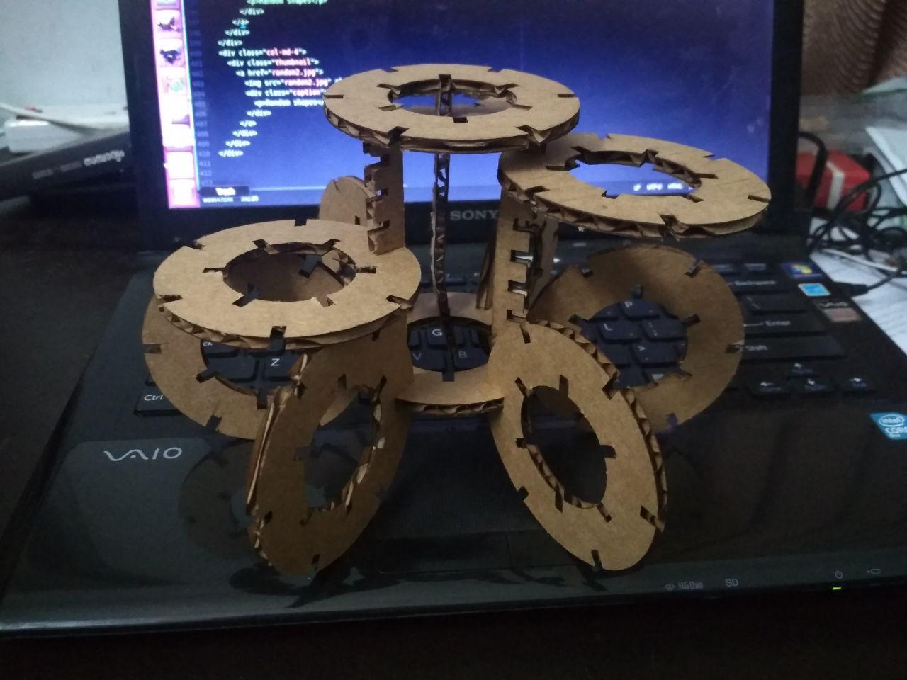
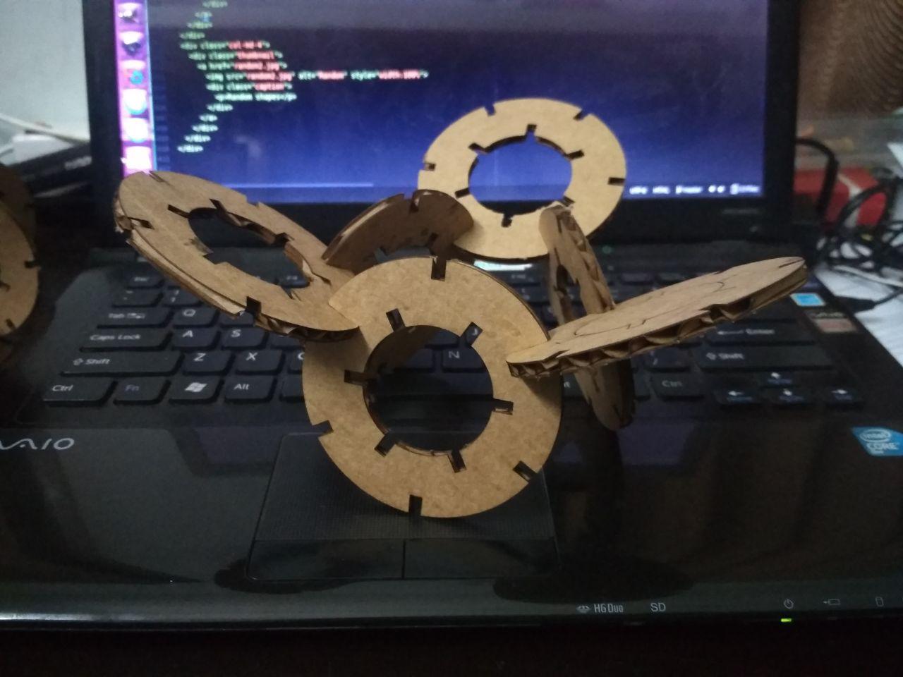
Below images are of the different ways in which the press fit construction kit was assembled.
Attempt in FreeCAD
I tried to make a kit that can be assembled in 3D. The individual shapes were made in FreeCad in the sketcher WB and then exported to svg. which was opened in Inkscape and edited.
I made a test cut of some parts but the parts were not fitting properly for the errors in the parametric design.
Download the file
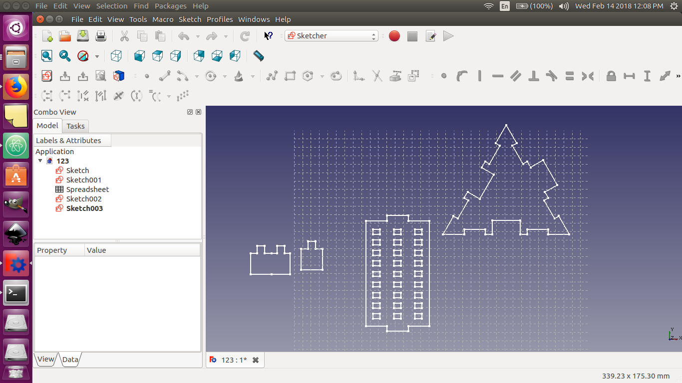
While working with FreeCAD, a strange thing was noticed. After creating a circle of radius 50mm with its centre at 0,0 in the skecther WB, when zoomed in with the grids on, one can observe that the radius is slightly shorter along the Y axis. However, the radius along X axis is exactly 50mm.
Vinyl Cutter
The machine we have at our lab is the Roland CAMM 1- Servo
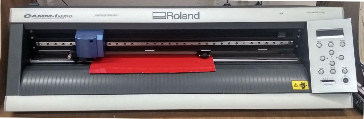
The machine can cut on different medium like vinyl, copper and epoxy. The end effector of the machine apply defined force on the cutting tool, to cut the material. Material sheet's of different size can be accepted by the machine. We can load the sheets in rolls or in pieces. Two rollers firmly holds the sheet against a base and moves the sheet back and forth. The rollers can be pulled up using the lever at the rear side for loading the sheet. Width of the sheet should be such that the two rollers are within the permissible range of operation (marked by white lines at the bottom portion of the rail over which the end effector moves) to find the width of the material.
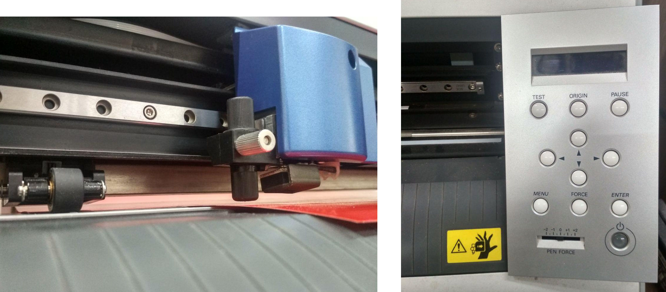
Below image on the left shows the end effector and one of the roller. The cutting tool is mounted inside the black cylinder shaped object. Below image on the right side shows the control panel of the machine with which we can set the origin by moving the end effector along the rail.
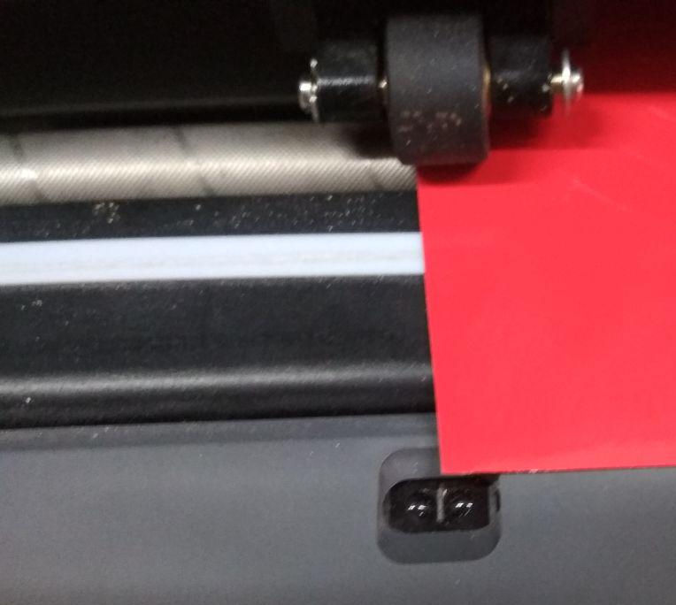
If the option selected is a roll, the machine will only measure the width of the sheet. The length of the sheet is measured using an IR sensor. The below image shows the IR emittor and sensor and also the textured rod over which the roller hold the sheet firmly. The white band seen is the sacrificial layer.
After placing the sheet, we have to move the end effector using the buttons and set the origin by pressing the "origin" button for 3 seconds.
The steps involved in the cutting operation can be summarised in three stages:-
1. Designing of the image in a 2D software.
A high resolution monochrome png image is to be designed, so as to be imported into "fab modules", which will make the path for cutting along the boundary of black and white.
2.Setting up the sheet, machine and cutting.
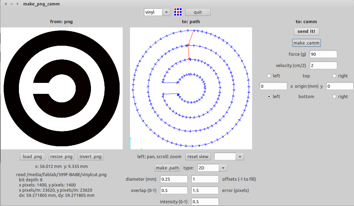
The .CAMM file required for the machine to make the cut is to be generated from the png image by using fabmodules. The force and velocity of the cutting operation can be configured in the fab modules. A vinyl sticker of 'Guy Fawkes mask' was cut to understand the overall operation. An image was downloaded from the internet to make the cut. A screenshot of the operation is displayed below.
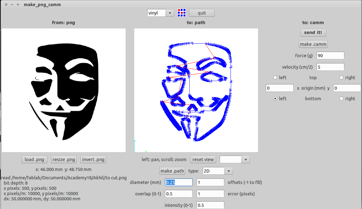
Here we can select different parameters of the cutting operations and also the origin. The size of the loaded image will be displayed at the bottom left. After loading the image, click 'make path' button and the window will display the path of cutting in blue lines.These can be adjusted by varying the value against the 'error (pixels)' buttons. We can also set the force and velocity of cutting. An increase in the force will increase the depth of cutting. Lower the velocity, proper is the cut.
After making the appropriate settings, click the 'make.camm' button. After this, click on 'send it' button to start the cutting operation.
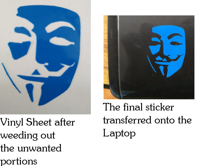
3. Weeding out the unwanted portions.
After the cutting operation, the next step is to remove the unwanted portions. It has to be carefully done using a sharp tool. By sticking a masking tape atop the vinyl sheet, the sticker with adhesive can be easily pulled out. The sticker along with the masking tape was then transferred onto the laptop surface. The masking tape was then carefully pulled apart leaving the sticker on the surface.
During the time of pulling out the sticker, small pieces had the tendency to pull apart from the whole. Weeding out the unwanted portions and isolating the sticker is a skill to be developed over practice.
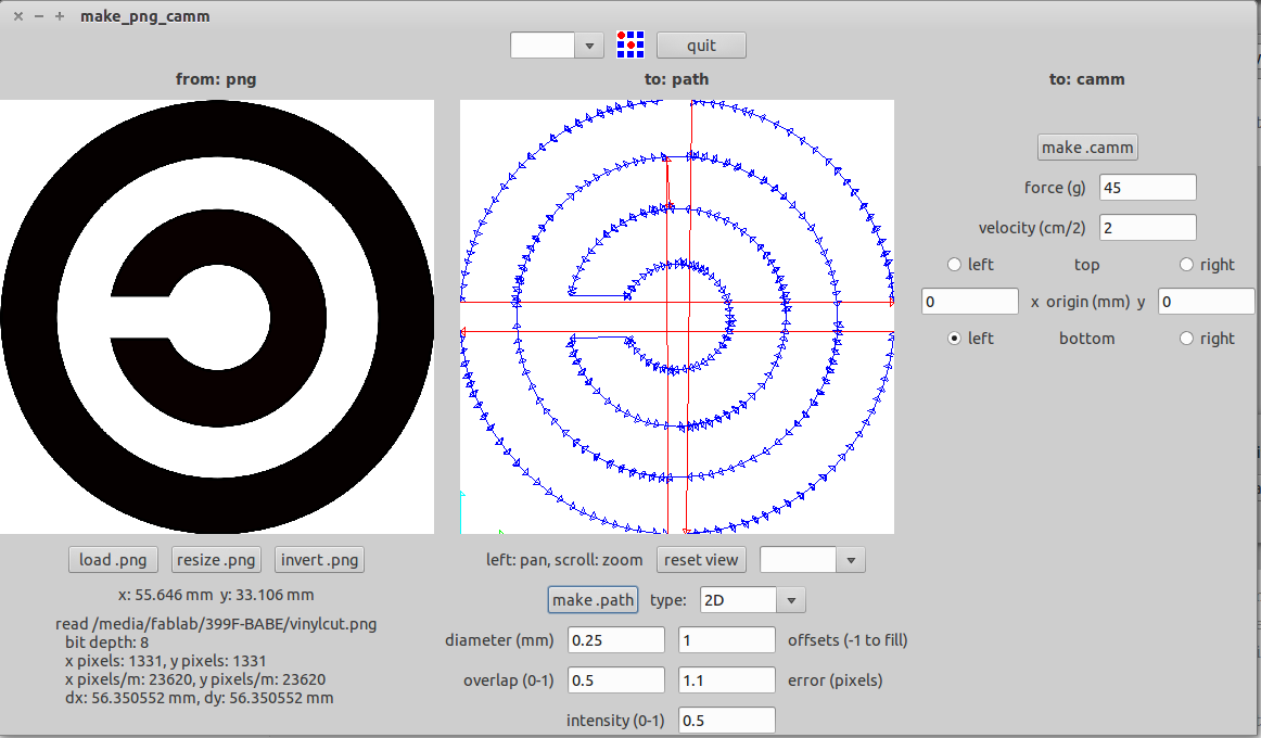
Designing and cutting the "Copyleft" symbol
A sketch was drawn with 4 circles in the sketcher workbench of FreeCAD. The inner two circles were trimmed to get the intial shape and the file was exported in dxf format. The dxf file was opened in Inkscape and each circle was made to path. Using the fill option in inkscape, the area between the circles were filled with black and white to get the final image. The image was then exported to png format.

Download the design files
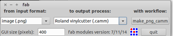
The fabmodules was opened in the computer and configured for making the .CAMM file required for the cutting.
At the first attempt, due to the low resolution of the png image, the circle was not well defined and the fab modules made a path that was not a smooth circle. Hence, the image was again exported from inkscape as a png image by increasing the resolution and was opened in fab modules.
However, the path was not the one required as the edges were left out which can be observed from the above image. To overcome this, the image was edited in GIMP by adding a white area all around the image so that fab modules could calculate the path correctly. The corrected image was imported again with the fab modules creating the correct path.
The cutting operation was completed and the below image shows the later stages of transferring the sticker onto the laptop.
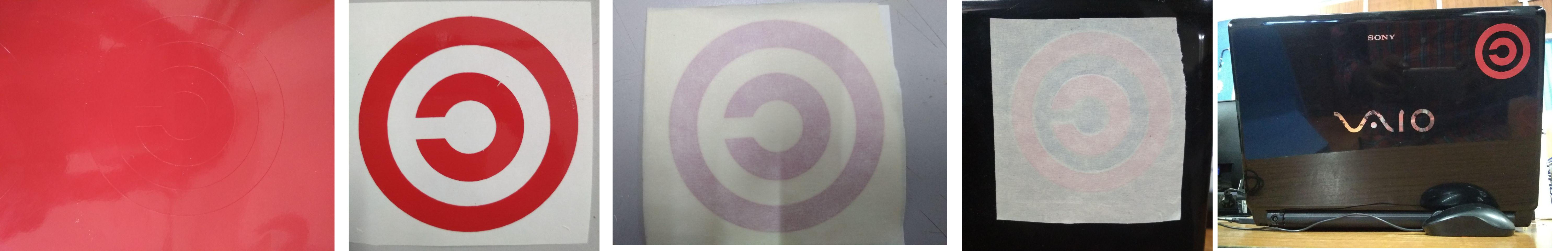
The first image shows the vinyl sheet after the cutting operation. The second image is the one after weeding out the unwanted portions. The third image shows the masking tape stuck over the vinyl. The fourth image shows the sticker along with the masking tape transferred onto the laptop surface. The final image shows the final sticker left over the laptop after pulling out the masking tape.