Week 9
Embedded Programming
This week's assignment was to read a microcontroller data sheet and to program the board we made during the Electronic Design Week with as many different programming languages and programming environments as possible. In addition to this, we had to make a comparison between the performance and development workflows for other architectures.
Data Sheet of a MCU
A Data sheet is the user manual of any product. In case of an electronic component, the data sheet gives all the technical informations about the component and enable the user to select the optimum component for a circuit, intergrate the component into the circuit, and to make the component work as intended. The data sheets are updated from time to time, and refering the latest one is always recommended. For getting familiar with the data sheet of a micro controller, i started with the data sheet of AtTiny 44A with which we made the board during the Electronic Design Week.
Attempt to understand the Data sheet for AtTiny 44A
The revision history of the data sheet of AtTiny 44A is specified at the bottom side of the page as "Rev. 8183F–AVR–06/12", from which we can understand that the data sheet was published on 06/12.
The data sheet begins with the general features of AtTiny 44A, and is then followed by the entire technical specification which are arranged in 27 chapters.
General Features
AtTiny 44 belongs to the AVR family (tinyAVR) of microcontrollers developed by Atmel with modified Harvard architecture(Physically separate storage and signal pathways for instructions and data).
In terms of bus-width (or bit), the Microcontrollers are classified into 8bit, 16bit and 32 bit. AtTiny44A is an 8 bit microprocessor, and hence can process 8 bits of data at a time. To process 8 bit data, the microcontroller has to take 8 bits of data from the memory. Thus each location in memory is 8 bit and data bus is also 8 bit.
In terms of "Architecture (Instruction Set)", microcontrollers are clasiified into Reduced instruction set computing (RISC) & Complex instruction set computing (CISC). AtTiny 44A is a low-power CMOS 8-bit microcontrollers having AVR enhanced RISC architecture. RISC architecture accepts simple instructions and are executed within a clock cycle. CISC architecture are used to run large program's where lot of memory is needed. Processors with this architecture attempts to minimize the number of instructions per program, sacrificing the number of cycles per instruction.
AtTiny44A can be programmed after intergrating into a system. It has 4KB of "In-System, Self-programmable Flash Program Memory", 256 Byte of "In-System Programmable EEPROM", 256 Bytes of "Internal SRAM", 12 general purpose I/O lines, 32 general purpose working registers, an 8-bit Timer/Counter with two PWM channels, a 16-bit timer/counter with two PWM channels, Internal and External Interrupts, a 8-channel 10-bit ADC, programmable gain stage (1x, 20x) for 12 differential ADC channel pairs, a programmable Watchdog Timer with internal oscillator, internal calibrated oscillator, and four software selectable power saving modes.
Operating voltage range of AtTiny44A is 1.8 to 5.5V and industrial teemperautre range is -40 to +85 degree celcius.
Pin configuration & Block Diagram.
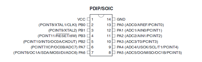
The location of the physical mark (used to identify the correct orientation during the soldering
operation) relative to the pin's can be understood from the figure.
The physical layout of the pin's and the respective functions/capabilities
are also abbreviated in the figure.
VCC - Supply voltage
GND - Ground
PB0,PB1,PB2,PB3 - 4 Ports of Port B.
PAO,PA1,PA2,PA3,PA4,PA5,PA6,PA7 - 8 Ports of Port A.
PCINT - The pin can be used for interupt operations.
XTAL - External clock. Crystal Oscillator can be connected.
RESET - Pin used for reset.
The RESET in the figure has a line over its text,
indicating the pin is "active low". Hence, to activate the pin, we have to pull
the pin low (0V) instead of pulling it high (VCC)
Below is the block diagram of AtTiny 44A.
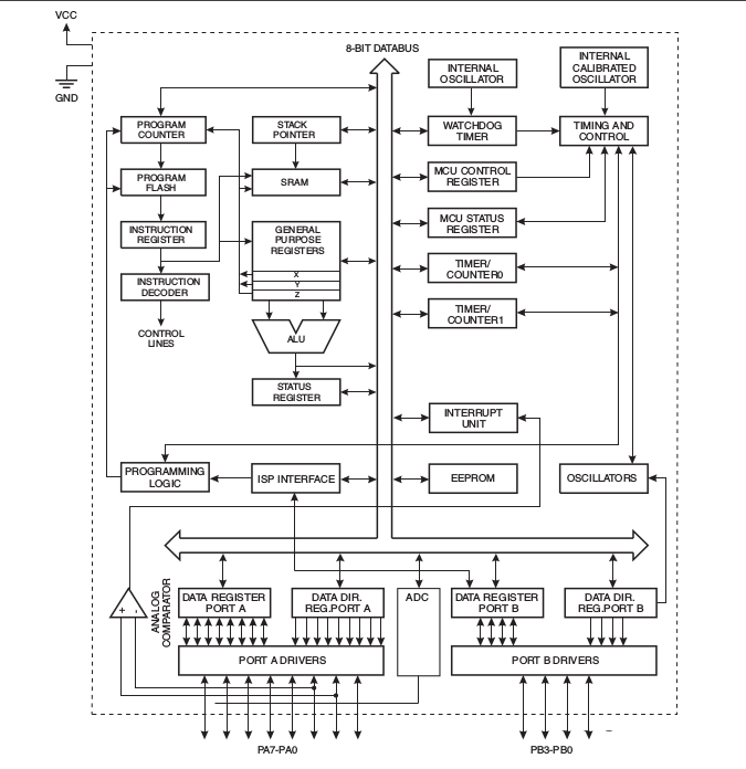
The AVR core combines a rich instruction set with 32 general purpose working registers. All 32 registers are directly connected to the Arithmetic Logic Unit (ALU), allowing two independent registers to be accessed in one single instruction executed in one clock cycle.
Idle mode stops the CPU while allowing the SRAM, Timer/Counter, ADC, Analog Comparator, and Interrupt system to continue functioning. ADC Noise Reduction mode minimizes switching noise during ADC conversions by stopping the CPU and all I/O modules except the ADC. In Power-down mode registers keep their contents and all chip functions are disbaled until the next interrupt or hardware reset. In Standby mode, the crystal/resonator oscillator is running while the rest of the device is sleeping, allowing very fast start-up combined with low power consumption.
Programming the micro controller
The programme is to be first written in C and the hex file has to be generated within an environment. The generated hex file has to be written onto the "flash programme memory" of the microcontroller using an ISP device. AtTiny44A has 4KB of flash programme memory.
It is advised to write the programme in a text editor like "Atom" which displays line number. During compiling of the code, if any errors are there, the compiler will indicate the line number of the code which returned error, with which we can debug the code easily. For the compiler to generate the "object" file (with .o extension), then to create the "Executable and Linkable Format" file (.elf) and then to create the final "hex" file(.hex), and then to flash the microcontroller, the following commands are to be entered into the terminal one after the other, after replacing the "filename" with the actual file name. To flash the memory of the microcontroller, it has to be connected to the computer through the FabISP.
avr-gcc -g -Os -mmcu=attiny44a -c filname.cavr-gcc -g -mmcu=attiny44a -o filename.elf filename.oavr-objcopy -j .text -j .data -O ihex filename.elf filename.hexsudo avrdude -c usbtiny -p t44 -U flash:w:filename.hexOnce all the commands are successfully executed, the microcontroller is flashed and can be tested. Alternatively, the programme can be compiled and flashed using a "make" file.
Below is the programme with which the the switch was made to act as a latching switch (which maintains its state after being activated).
  // This program is written to power on/off an LED, and to maintain its status until a switch is pressed. (Latching Switch)
  // Akhil Hari 24-06-2018
  // Fab Academy 2018, Fab Lab Trivandrum, India
  // Embedded Programming week

  // MCU - ATTINY44-SSU
  // LED is connnected to PA7.
  // Switch is connected to PA3.
  // PA3 is externally pulled up.
  // Pressing the switch makes PA3 LOW.

  #include<avr/io.h>              // Including the header file for Atmel AVR MCU's input output defenitions.
  #define F_CPU 20000000          // Initilaising external clock of 20MHz
  #include<util/delay.h>          // Header file for the delay function which makes's the MCU busy for a specified time

  int main(void)  {               // Setting up the Ports and Pins of the MCU. Run once.
  DDRA = 0b10000000;              // Defining PA3 as input and PA7 as output.
  PORTA = 0b00001000;             // PA3 is pulled up and PA7 is pulled down.
  while(1)  {                     // This is an infinte loop and will run repeatedly.
    if(!(PINA & 0b00001000)){     // When button is pressed,value of PINA reads 0bxxxx0xxx making the statement true
                                  // and the commands inside the "if" loop will be executed.
                                  // When button is not pressed, the "if" statement becomes false and will not be executed.
      PORTA |= 0b10000000;        // PA7 is made high to turn ON the LED.
      _delay_ms(50);              // Delay to take care of bounce effect of switch.
    }
    else if(!(PINA & 0b00001000)) {   //When the button is released, value of PINA becomes 0b10001000
                                      //making the "if" statement false and the MCU will execute the "else if" statement.
                                      //When the button is pressed again, the value of PINA becomes 0b10000000 making the
                                      //"else if" statement true and the commands inside the "else if" loop will be executed.
      PORTA &= 0b01111111;            // PA7 is made low to turn OFF the LED.
      _delay_ms(50);                  // Delay to take care of debouncing effect of switch.
    }
  }
  }
Programming and Flashing using Arduino IDE.
For using the Arduino IDE, the computer has to be first installed with the Arduiono IDE software. Then the boards for AtTiny 44A has to be added to the IDE. For doing the same, open the Arduino IDE and click File > Preferences, and under the Additional Board Manager's URL in Settings tab, paste the following and click Ok.
https://raw.githubusercontent.com/damellis/attiny/ide-1.6.x-boards-manager/package_damellis_attiny_index.json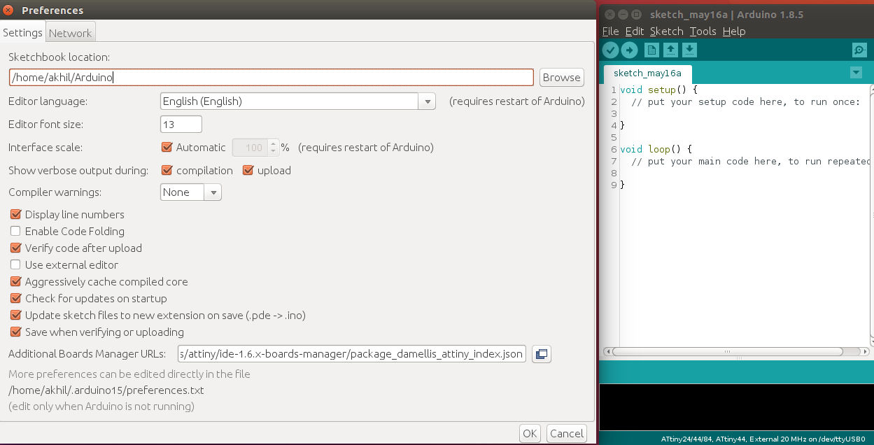
The Arduino IDE has to be then configured with the correct Programmer, Board, Processor and clock. This can be done by selecting the appropriate option on the Tools menu. Under the Tools menu, set the options as below.
Set the Board option to ATtiny24/44/84
Set the Processor option to ATtiny44
Set the Clock option to External 20MHz
Set the Programmer option to USBtiny ISP
Now the Arduino IDE is set to programme the ATtiny 44. To set the fuses, click Tools > Burn Bootloader. After writing the code, it can be compiled using Sketch > Compile/Verify. To flash the microcontroller, click Sketch > Upload using Programmer .If any error happens during the compiling/Uploading time, it will be displayed in the bottom window.
The below sketches were uploaded to the Processor in Arduino IDE and turned out to be successful after investing time in learning Arduino.
1. LED is powered on as long as the button is pressed.
  // This program is written to keep an LED ON, as long as a switch is pressed.
  // Akhil Hari 24-06-2018
  // Fab Academy 2018, Fab Lab Trivandrum, India
  // Embedded Programming week

  // MCU - ATTINY44-SSU
  // LED is connnected to PA7.
  // Switch is connected to PA3.
  // PA3 is externally pulled up.
  // Pressing the switch makes PA3 LOW.
  void setup() {            // This is the setup code and will run once

    pinMode(7,OUTPUT);      // LED is connected to PA7. Initialise PA7 as output
    pinMode(3,INPUT);       // Switch is connected to PA3. Initialise PA3 as input
  }

  void loop() {             // This is the main code and will run forever.
    int x=digitalRead(3);
    if(x==HIGH)             // Check the status of Swith. By default, the switch is pulled up externally(In high state).
    {
      digitalWrite(7,LOW);  // LED is turned off.
      delay(100);           // delay of 100ms to account for the bounce effect of the switch.
    }
    else
    {
      digitalWrite(7,HIGH); // LED is turned on.
      delay(100);
    }
  }
2 LED is powered off as long as the button is pressed.
  // This program is written to keep an LED OFF, as long as a switch is pressed.
  // Akhil Hari 24-06-2018
  // Fab Academy 2018, Fab Lab Trivandrum, India
  // Embedded Programming week

  // MCU - ATTINY44-SSU
  // LED is connnected to PA7.
  // Switch is connected to PA3.
  // PA3 is externally pulled up.
  // Pressing the switch makes PA3 LOW.
  void setup() {

    pinMode(7, OUTPUT);
    pinMode(3, INPUT);
  }

  void loop() {
    int x = digitalRead(3);
    if (x == HIGH)
    {
      digitalWrite(7, HIGH);
      delay(100);
    }
    else
    {
      digitalWrite(7, LOW);
      delay(100);
    }
  }
3. Toggle Switch
LED will change status everytime the switch is pressed.
  // This program is written to toggle the status of an LED when a button switch is pressed.
  // Akhil Hari 24-06-2018
  // Fab Academy 2018, Fab Lab Trivandrum, India
  // Embedded Programming week

  // MCU - ATTINY44-SSU
  // LED is connnected to PA7.
  // Switch is connected to PA3.
  // PA3 is externally pulled up.
  // Pressing the switch makes PA3 LOW.
  const int buttonPin = 3;  // The value of the integer "buttonPin" is defined as 3
                            // (Since switch is is connected to Arduino Pin No. 3 (PA3)
                            // Change this value to the corresponding arduino pin number if switch is connected to any other pin.
  const int ledPin = 7;     // The value of the integer "ledPin" is defined as 7
                            // Since switch is is connected to Pin 7 (PA7))
                            // Change this value to the corresponding arduino pin number if LED is connected to any other pin.
  int x = 1;                // value of the integer x is set to one.

  void setup() {
    pinMode(buttonPin, INPUT);  // Intitialise buttonPin as input
    pinMode(ledPin, OUTPUT);    // Initilaise ledPin as output
  }

  int oldButtonState = LOW;     // This integer will store the last known state of the button

  void loop()
  {
    int newButtonState = digitalRead(buttonPin);  // Get the current state of the buttonPin

    if (newButtonState == LOW && oldButtonState == HIGH) {  // Has the buttonPin went LOW since we last read it?

      if (x == 0) {                 // On status change of button and if x is equal to 0, below three lines will be executed.
        digitalWrite(ledPin, HIGH); // LED is powered on
        delay(100);                 // eliminate bounce effect of switch
        x = 1;                      // value of x is made equal to 1 to execute the "else" statement on Line 38 when the switch is pressed again.  .

      } else {                      // On status change of button and if x is not equal to 0, below three lines will be executed.
        digitalWrite(ledPin, LOW);  // ledPin is made low powering off the LED.
        delay(100);                 // eliminate bounce effect of switch.
        x = 0;                      // Value of x is made equal to 0 to execute the "if" statement on Line 33 when the switch is pressed again.
      }
    }

    oldButtonState = newButtonState;// Store the button's current state to check if it's changed next time around
  }