This week's assignment has been very exciting for me (like the other weeks ;)). I enjoyed the compilation of 3D scanning and printing technologies in Neil's Wednesday lecture. I have worked heavily on imaging with the confocal microscope and seen the Atomic Force microscope in my Ph.D. days. I own a Sony Playstation and have used an Intel Realsense camera at my workplace. I have used the 3D printers in Fablab twice. That sums up my previous exposure to this area.
After Neil's lecture, I was especially struck by the difference in additive and subtractive manufacturing and the design constraints to be taken into account while 3D printing. I had never thought about these concepts earlier. To me, 3D printing was just making plastic objects (I tingle with embarrassment now at my earlier ignorance).
Group assignment:
Testing the design rules for our 3D printer
We downloaded two thingiverse files to test our printer:
File 1 and
File 2
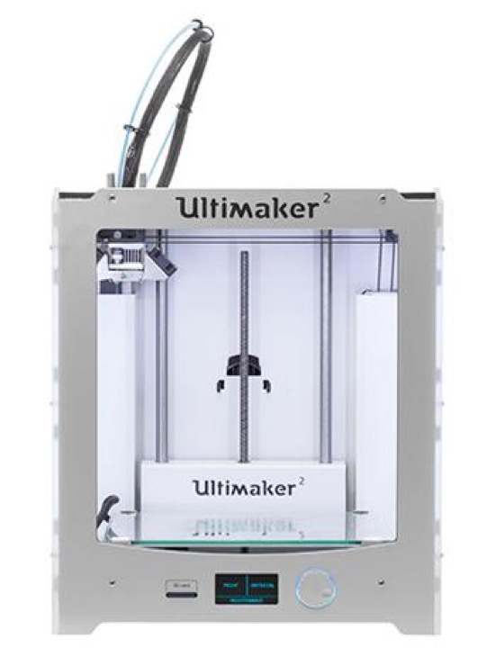
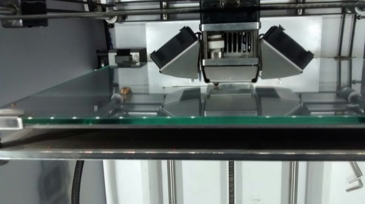
This is the 3D printer that we used this week - the Ultimaker 2. It operates on the principle of 'Fused Deposition Modeling' (FDM). It has only one nozzle to extrude and hence the same material is used for both printing and supporting.
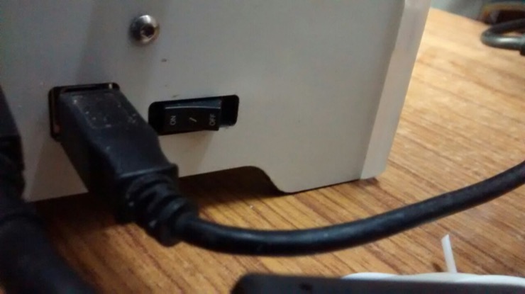
The on/off switch is located at the back of the machine.
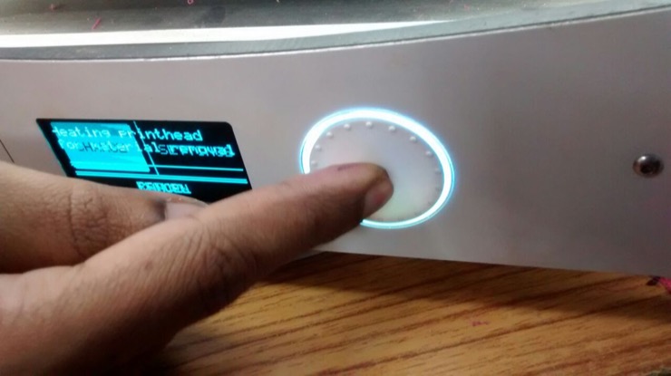
The display and controls in the front of the machine. The button allows us to rotate to scroll through a menu and push to confirm a selection.
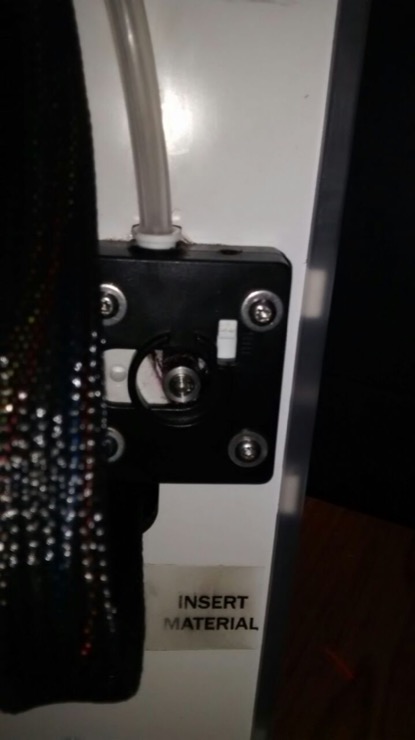
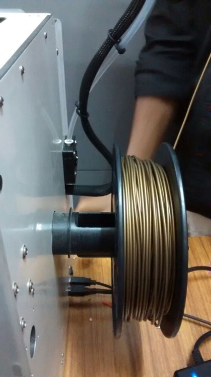
The slot at the back of the machine to insert the print material.
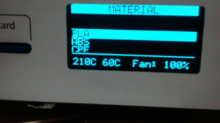
In our lab, we use PLA as the print material, with the nozzle temparature at 210 deg C and bed temperature at 60 deg C. The print material for the Ultimaker 2 is consistently maintained as PLA, to avoid damage to the nozzle as different materials have different melting temperatures and their debris may block and damage the nozzle.
The spool of PLA to be loaded into the machine.
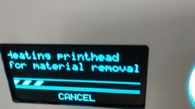
Simple instructions to follow to load the material.The printhead is heated first to facilitate removal of the previous material.
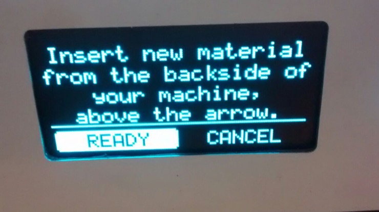
The new material is to be inserted through the opening at the back of the machine.
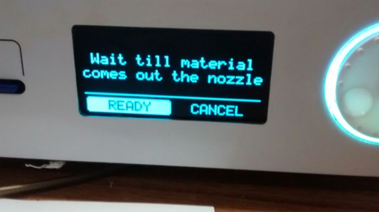
The nozzle heats up and we wait till the material melts and extrudes out.
The printer bed moves up and the nozzle starts extruding the material.
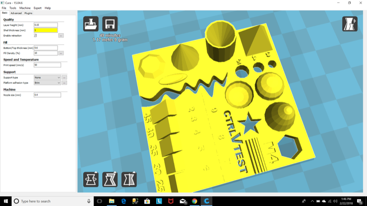
The test file (.stl) opened in Cura software to generate the gcode file. The shell thickness of 1mm is highlighted as an error because it has to be a multiple of the nozzle size (0.4mm).
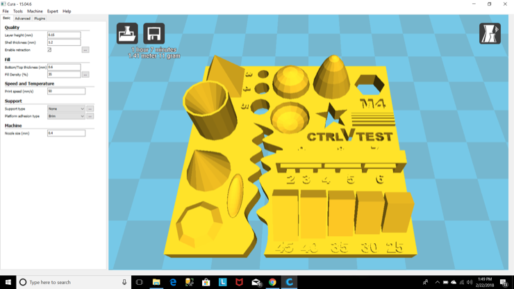
Shell thickness 1.2mm, Layer height 0.15mm, Fill density 35, print speed 50mm/s, no support, Brim type platform adhesion, nozzle size 0.4mm
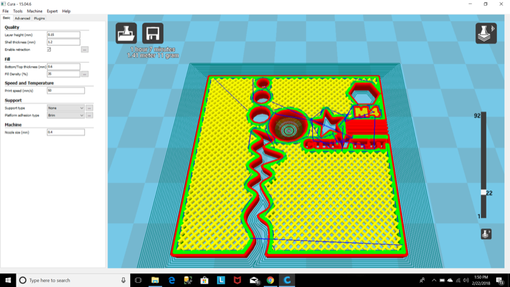
Checking the layers in Cura software. Time to be taken for the print job is 1 hour and 7 minutes.
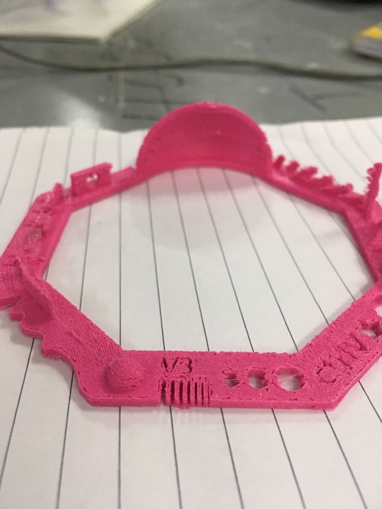
The overhangs came out well but the bridges were not complete and the very fine lines were not well-defined. We wanted to test again, with a lower layer thickness of 0.1mm.
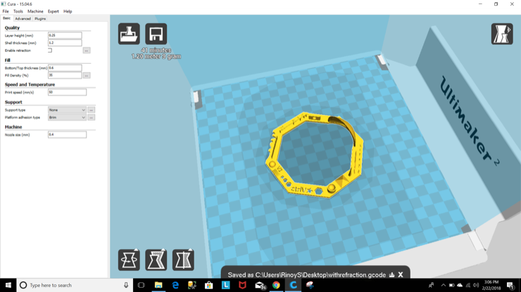
Generating the gcode file in Cura for the next test print. A 41-minute print job.
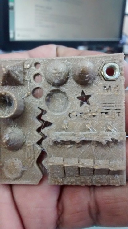
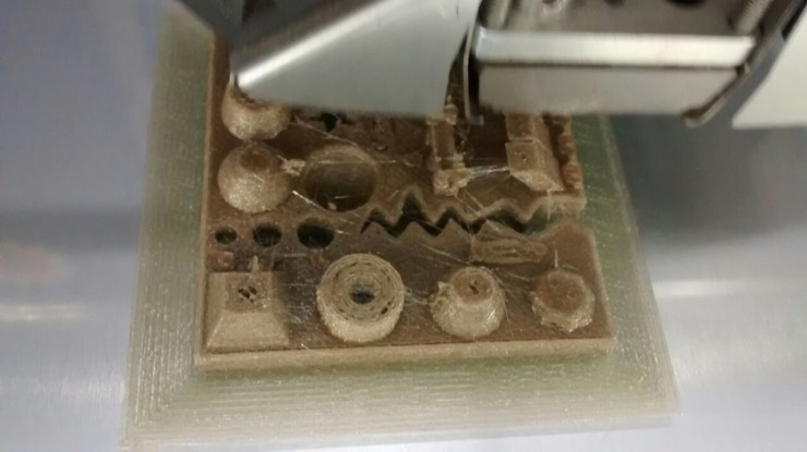
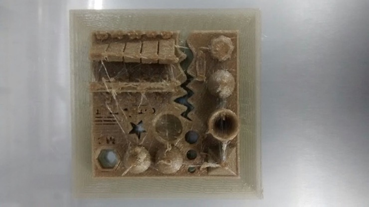
The minimal distance test lines from 0.1 to 0.7mm are present.
The overhangs at lesser angles require more support material.
The bridges at 4mm, 8mm and 16mm distance have not formed. Only the 2mm bridge is complete.
The walls of thickness 0.5, 0.6 and 0.7mm are present. The 0.1-0.4mm walls are missing.
Designing and 3D printing a small object that cannot be made subtractively
I referred to these webpages to read about prior experiences in designing and 3D-printing the ball-and-socket joint :
Link 1 and
Link 2. I understood that the tolerance gap between the ball and socket has to be optimized and it varies from one machine to another. I put a lot of thought and took a lot of input from different people while working on this design, to get it right in fewer tries and lesser time.
I realized that I have to think about the support material that is generated during printing. In Ultimaker 2, the same material is used for printing and supporting. Hence, while making movable parts, if support material is generated between them, it has to be broken away. If the parts are weak, it could break them. To solve this, we could plan to lay the object on the print bed in such a way that very less support material will be generated between the moving parts. This realization helped me solve the issues that I faced in this assignment.
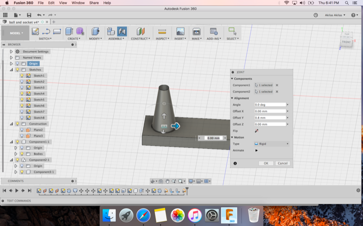
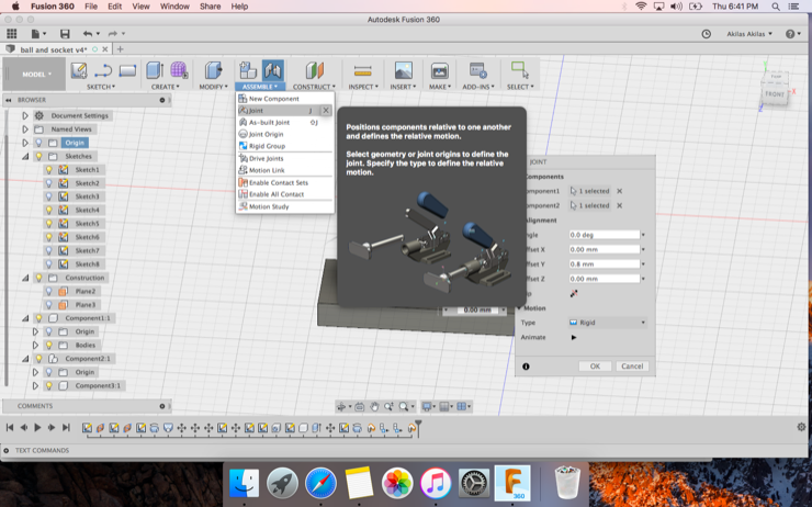
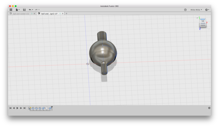
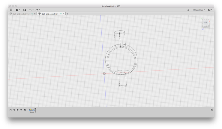
Used Fusion 360 software for my designing. I used parameters: ball diameter and gap, so that socket diameter=ball diameter+gap.
I learned something new in this exercise - assembling components. It was pretty exciting to see the animation.
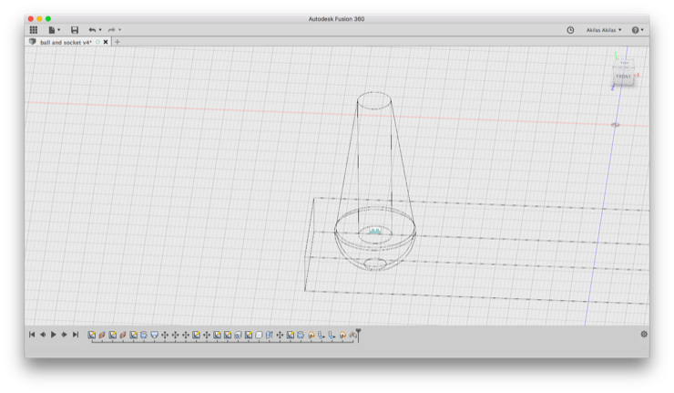
Vinod, our instructor, pointed out something that should have been obvious to me. The socket did not have any overhang to prevent the ball from falling out. So this design is trashed.
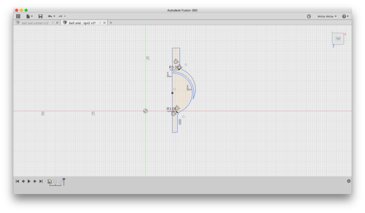
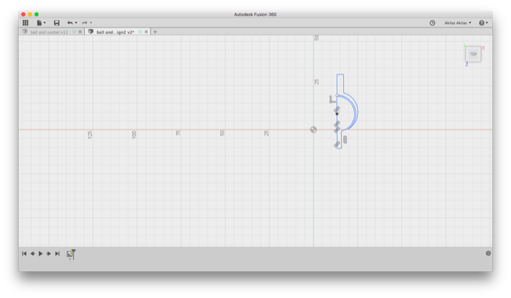
Lancy went to the whiteboard and drew this outline, asking why I'm not going for this simple design. Draw the cross-section and then revolve. It did seem much easier than my previous strategy.
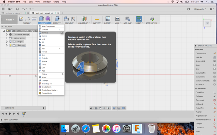
Using the revolve function to make the 3D object from the cross-section.
The end-result which I exported as stl file and opened in Cura to convert to gcode file.
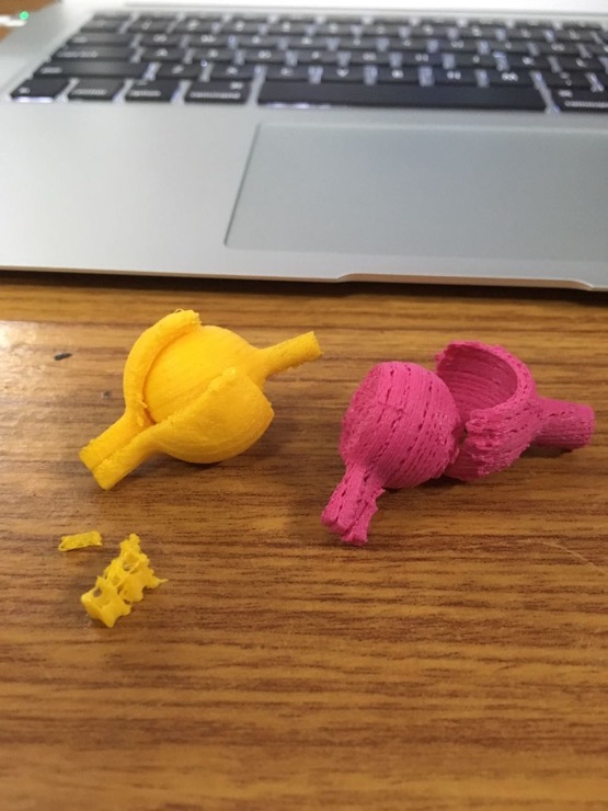
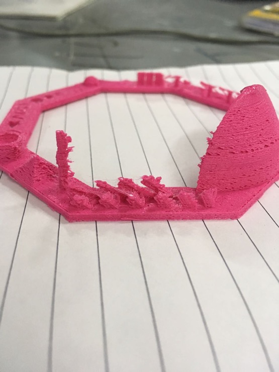
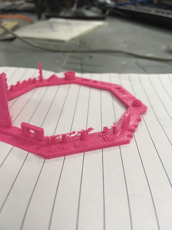
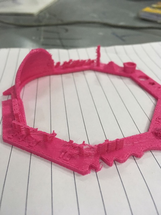
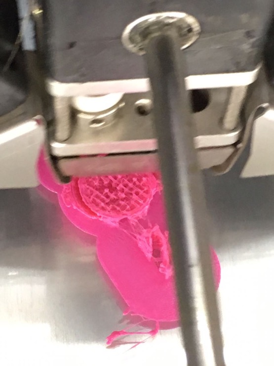
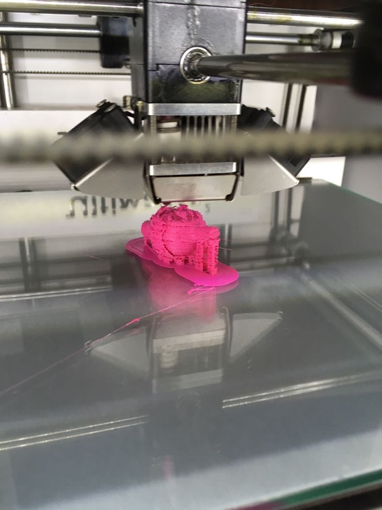
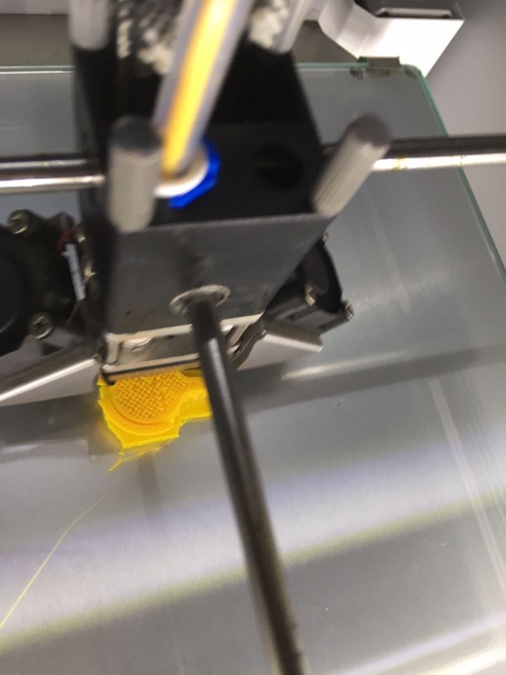
Printing in progress.. I could see right away that the socket wall was too flimsy. It would break if I tried to break away any support material between the ball and socket."
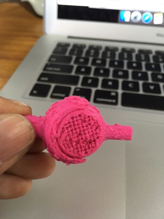
There was no support material between the ball and socket except at the bottom, where both the walls just fused together. I also noted that 'brim' platform adhesion may not be needed next time.
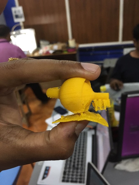
The printer head stopped extruding any material midway. The machine had to be fixed. So this is my unfinished, dysfunctional ball-and-socket joint attempt.
For the next try, I increased the gap between the ball and socket and also increased the socket overhang to prevent the ball from falling out.
I showed this design to our instructors. Vinod advised to increase the socket wall thickness.
Lancy advised to decrease the socket overhang a little to allow more freedom of movement for the ball. These quick and brilliant observations and Rahul's idea to remove a little socket wall, so that the ball will stick to the base and not to the socket while printing, saved the day for me.
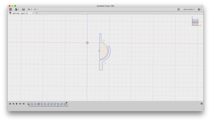
I revolved the ball to 360 degrees and the socket only to 300 degrees, to get the gap in socket.
I exported file as stl to Cura and then saved as gcode. In Cura, I changed orientation such that the gap in the socket was the portion in contact with the printer bed.
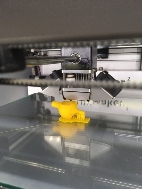
I chose 'raft' platform adhesion and support material only to the base plate. Thankfully, the printing went smoothly, without any hitch.
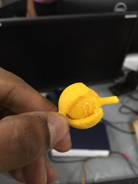
Post-processing involved chopping away the extra support material using a pen-knife.
Upon Lancy's suggestion, dropped some oil on the ball to enable smooth movement.
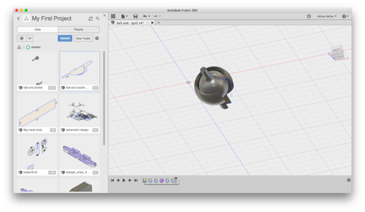
Proud of the day's work and learning outcomes. Check the video at the top of this page to see the ball-and-socket joint in action.
Download the design files:
(.stl) and
(.f3d)
3D scanning an object
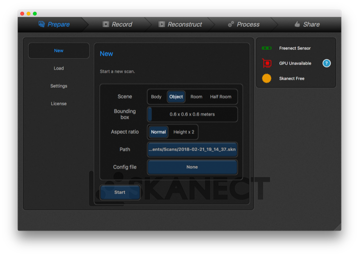
For 3D scanning, I downloaded Skanect and the Xbox 360 controller driver for Mac. I used the Microsoft Kinect camera in our lab.
Realization : scanning a bigger object is easier and much more accurate.
Choose 'Object' to scan in Skanect.
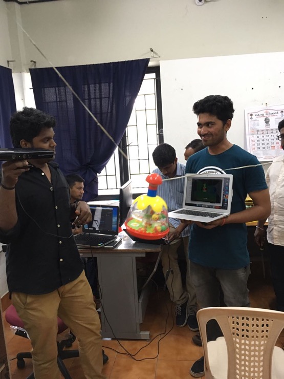
I was trying to scan this toy first, with the help of my fellow fabbies. However, I realized that this was too small and also, the little balls inside the toy would jump around, distorting and interrupting the scan.
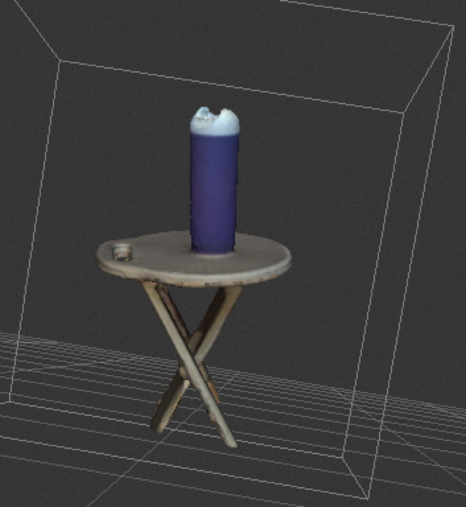
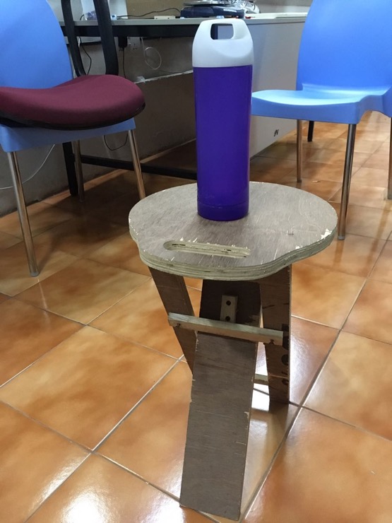
I decided to scan a bigger target - my water bottle on a stool. I took the Kinect camera in my hand and moved around slowly, checking the software for progress.
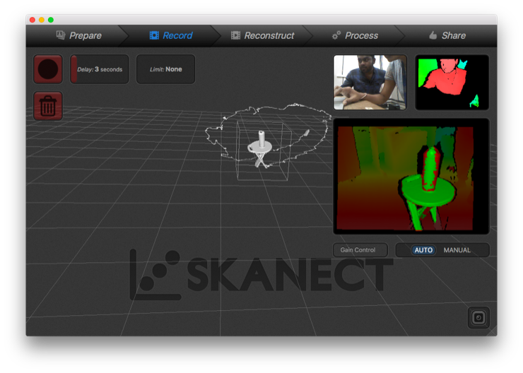
The trace path around the object is shown here. You can also see the object being detected by the software in the area shaded green.
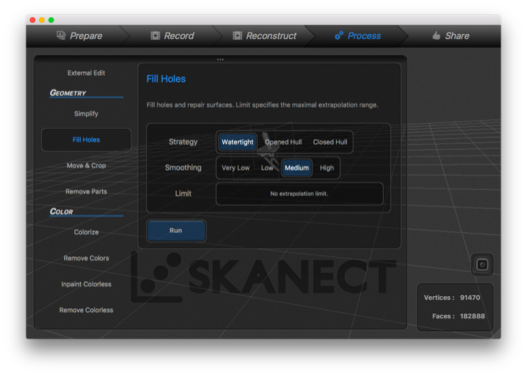
Played around with some post-processing options in Skanect to fill holes, etc.
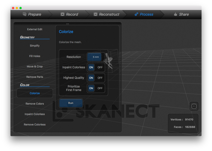
Colorized the scan. Was thrilled to see the original colours of the objects pop up in the 3D scan.
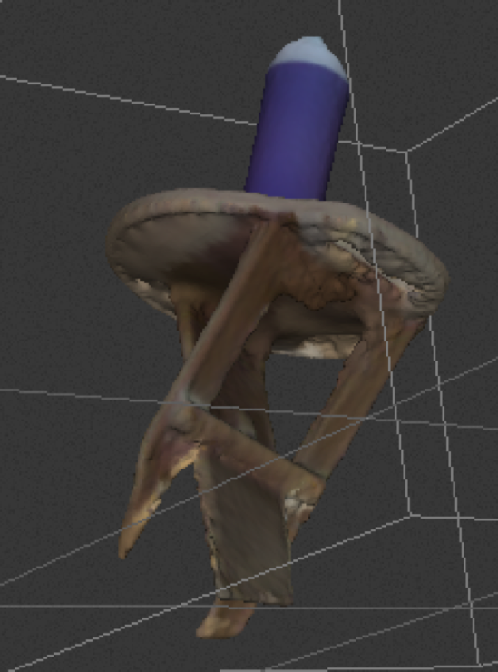
This is a screenshot of the scan. See below for the stl file.
Some portions of the stool that I missed capturing when moving around the objects.
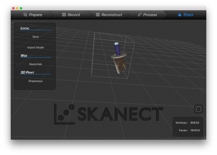
Can save the scan and export in different formats from the software.
Download the stl file
here.